Sensor Interfaces and Processing Techniques
This comprehensive overview covers various types of sensors, including those that produce voltage, current, or charge. It delves into resistive, capacitive, and other sensor types, detailing their input and output quantities and the physical/chemical properties they sense. The content also explores frequently used sensor interfaces like Instrumentation Amplifiers and Trans-Impedance Amplifiers.

Download Presentation

Please find below an Image/Link to download the presentation.
The content on the website is provided AS IS for your information and personal use only. It may not be sold, licensed, or shared on other websites without obtaining consent from the author.If you encounter any issues during the download, it is possible that the publisher has removed the file from their server.
You are allowed to download the files provided on this website for personal or commercial use, subject to the condition that they are used lawfully. All files are the property of their respective owners.
The content on the website is provided AS IS for your information and personal use only. It may not be sold, licensed, or shared on other websites without obtaining consent from the author.
E N D
Presentation Transcript
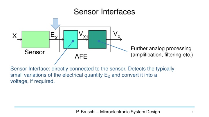
Sensor Interfaces Further analog processing (amplification, filtering etc.) Sensor Interface: directly connected to the sensor. Detects the typically small variations of the electrical quantity EXand convert it into a voltage, if required. P. Bruschi Microelectronic System Design 1
Sensors that produce a voltage Output quantity electrical Input quantity to be sensed. Temperature difference Temperature Fluid flow rate Infrared radiation (bolometers) Gas concentration (catalytic sensors) Ion concentration in electrolytes Gas concentration probes ) Magnetic Field Position (Proximity) Current measurement Force (ac detection) Acoustical pressure, acceleration. physical or chemical Sensor type Thermoelectric sensors Voltage Electrochemical sensors (e.g.. lambda Hall sensors Piezoelectric sensors P. Bruschi Design of Mixed Signal Circuits 2
Sensors that produce a current or a charge Output quantity electrical Input quantity to be sensed. Infrared, Ultraviolet radiation Imagers Proximity Opacity (e.g. smoke detectors) Visible radiation Ionizing radiation particle detection physical or chemical Sensor type visible and Current Optical sensors (photodiodes) CCD imagers and Charge High energy particle detectors P. Bruschi Microelectronic System Design 3
Resistive sensors Output electrical quantity Input physical or chemical quantity to be sensed Temperature Fluid flow rates Fluid velocity anemometers) Gas concentration (catalytic sensors) Proximity Strain (strain gauges) Force (e.g. electronic scales) Pressure (barometers) Altitude Acceleration Gas or vapor concentration Magnetic field Proximity Orientation (e.g. electronic compass) Visible radiation Sensor type Thermistor (Resistive Detectors) and RTDs (e.g. hot wire Temperature Piezo-resistors Resistance Chemi-resistors Magneto-resistors Photo resistors P. Bruschi Microelectronic System Design 4
Capacitive sensors Output electrical quantity Input physical or chemical quantity to be sensed. Sensor type Acceleration Angular velocity (gyroscopes) Pressure Gas concentration (e.g. humidity sensors) CapacitanceCapacitive sensors (mechanical) Capacitive sensors (chemical) P. Bruschi Microelectronic System Design 5
Frequently used sensor interfaces Output quantity Type of Interface Voltage Notes InstrumentationAmplifier (In-Amp) Resistors should be mounted in a Wheatstone bridge configuration or biased by a current. InstrumentationAmplifier Resistance Resistor must be biased with a voltage in order to produce a current Trans-ImpedanceAmplifier (TIA) Current Trans-ImpedanceAmplifier (TIA) Converting current by means of a periodic voltage waveform capacitance into a Trans-ImpedanceAmplifier (TIA) Capacitance Charge amplifier (switched capacitor) Charge amplifier (switched capacitors) Charge P. Bruschi Microelectronic System Design 6
Trans-Impedance Amplifier (TIA) = v Z i Goal out s Sensor that produces a current (Norton equivalent circuit) iZ 1 Z = = S i i i Z S S Z Z + Z Z + 1 S = V Z i S out Z i i Z S P. Bruschi Microelectronic System Design 7
Sensitivity vs Accuracy 1 Z Z iZ = 1 i i i = v Z i Z S S Z Z out Z + 1 S S = v Z i Z Z 1 v Z i out Nominal law S out S S Z should be small (magnitude) to reduce the relative error (high accuracy) Z should be large (magnitude) to obtain a high sensitivity For sensor marked by small values of the ZSimpedance, finding a value of Z that satisfies both requirements is often impossible P. Bruschi Microelectronic System Design 8
A possible solution: the TIA iZ operational amplifier iZ Ideal case (perfect virtual gnd) i i = Z S 0 = v Z i out s v = = An i TIA k Z Sensitivity of the TIA stage (transimpedance) s P. Bruschi Microelectronic System Design 9
TIA non-idealities A Finite gain Finite input impedance = 0 A f + 1 jf p Typical dominant-pole frequency response ZT = // Z Z Z T S A P. Bruschi Microelectronic System Design 10
TIA: input impedance ZIN = // Z Z Z T S A Z K v = = = Z out v K A IN M 1 M in Z + = Z IN 1 A f f + + 1 jf 1 jf 1 Z p = = p = Z Z Z IN A f + f 1 A + + + + 1 1 j 0 1 A jf 0 ( ) f + 0 1 A f + 1 jf 0 p f0 p p P. Bruschi Microelectronic System Design 11
TIA: input impedance ZIN f + 1 j f Z p = Z IN f + 1 A + 01 j f 0 ( ) + 1 f A f A f 0 0 0 p p f0 is defined as the frequency at which the amplifier gain magnitude is unity (0 dB) P. Bruschi Microelectronic System Design 12
TIA input impedance f + 1 j f Z p = Z IN f + 1 A + 01 j f 0 fP f 0f f ZIN= jZ 0f P. Bruschi Microelectronic System Design 13
Error due to the finite input impedance Error on the current IZ Ideal case: = V Z I A S iZ 1 Z Z Z = = I I T iZ Z S + Z Z + 1 IN IN T T Z Z Z Z 1 IN I I IN T Z S T Z IN A Z T P. Bruschi Microelectronic System Design 14
Error on the output voltage Ideal case: = V Z I This voltage is affected only by the error due to: A S I I S Z = V ina Z A I Z ina iZ V A = = V v I Z I Z A A in Z Z 1 A I Z = 1 V I Z Z 1 A A Z + 1 Two error contributions P. Bruschi Microelectronic System Design 15
TIA non-ideality: Noise and offset Equivalent noise source of impedance Z Input referred noise current of the amplifier Thermal Noise: S = ( ) Z 4 Re kT VnR For noise calculations, we will neglect finite gain effects (hypothesis of perfect virtual gnd) Input referred noise voltage of the amplifier P. Bruschi Microelectronic System Design 16
Effect of in and vnR in in = + v i Z v An n nR P. Bruschi Microelectronic System Design 17
Effect of the voltage source Z Z = + 1 v v An n T P. Bruschi Microelectronic System Design 18
Total output noise voltage and input referred noise current Z + + 1 v Zi v v An n n nR Z T v v = = = An i TIA k Z An n RTI i TIA k s 1 1 v v Z + + = + nR i i v : n for Z n rti i i n n RTI n n Z Z Z T T P. Bruschi Microelectronic System Design 19
TIA used to read capacitive sensors physical quantity to be sensed ( ) ( ) f X = = + C C f X Balanced differential sensor (e.g. MEMS accelerometer) 0 X C C 0 R ( ) f X = = + Pseudo differential sensor (e.g. pressure sensor) C C 0 X Differential capacitive sensor C C 0 R C0is typically a large capacitance which does not vary with X, but is widely affected by process spread and often depends on temperature = C C C The interface must read: X R P. Bruschi Microelectronic System Design 20
Transformation of C into a current ( ) t S = ( ) cos v t V S SM = + C C C S X R short-circuit current dv dt dv dt ( ) = = sin( ) C C V t ( ) S S i t C C X R SM S S S R X P. Bruschi Microelectronic System Design 21
Use of the TIA to read current IS Substituting the Norton equivalent circuit to the sensor, we have the usual TIA configuration, with Z=R ( ) t = R i t = C t ( ) ( ) sin( ) v RV t A S SM S S P. Bruschi Microelectronic System Design 22
Finite gain error = // Z Z Z T S A Z IN 1 A Z = Z T S j C S S Hypothesis: ZAis a pure capacitance 1 = = + with Z C C C 1 T T S A j C = Z S T A j C S A f f f f = f f f S Z jZ jR 0 P S IN 0 0 P. Bruschi Microelectronic System Design 23
Finite gain error f 1 Z S Z jRf = IN Z A IN T Z j C T S T 0 1 1 f C f f f f f f f f S Rf = S S = S S A 1 RC 0 0 0 2 2 S T T 1 RC = f 2 T P. Bruschi Microelectronic System Design 24
Equivalent input current noise 1 1 v 1 + + nR (TIA) i i v = Z n RTI n n Z 1 R Z Z T j C T S T = Z R v + + nR R n RTI i i v j C n n S T = 4 S kTR 1 C R + v vnR = + + 1 nR R i v j C n n S T j S T 1 4 kTR R ( ) 2 + + 1 S S S C ( ) I RTI In Vn S T 2 2 C R S T P. Bruschi Microelectronic System Design 25
Equivalent capacitance noise 1 4 kT R ( ) 2 + + + 1 S S S C ( ) I RTI In Vn S T 2 C R S T The input quantity of the described interface is a differential capacitance. Thus, we need to refer the noise to C: i C k = n rti n C I kC-Iis the sensitivity from the input capacitance C to the current Is. Calculation of kC-Iis not straightforward because there is a modulation process involved P. Bruschi Microelectronic System Design 26
Complete interface synchronous demodulator gain = KD ( ) C t C t V = = V sin( sin( ) i v t S SM R S S ( ) ) t (ideal TIA) A SM S S P. Bruschi Microelectronic System Design 27
Signal and noise paths in the frequency domain C(f) Sum of negative and positive replica Capacitance Signal path: jV = k RV k jRk 2 jV SM S D D SM S jV 2 SM S 2 SM S 2 C Vout Noise path (PSDs): Input current ( ) 2 2 = jRk 2 2 Rk D D Input referred capacitive noise: jRk jRk SIBB-RTI D D LPF Vout ( ) ( ) 2 2 S f k R Vout S In rti = = S D S ( ) Cn 2 2 V k R k S SM D C Vout P. Bruschi Microelectronic System Design 28
Input referred noise 1 4 kT R 2 S ( ) 2 + + + = 1 S S S C S IBB RTI V ( ) I RTI In Vn S T ( ) 2 Cn 2 C R S T S SM Only broadband components (no flicker, no offset)! 1 4 S S kT ( ) 2 + + + 2 1 In Vn 2 S C ( ) ( ) ( ) Cn T 2 2 2 V V C R V R SM S SM S T S SM In order to reduce capacitance noise (and then, improve resolution): Increase S (fS) Increase R Increase VSM Limited by available Vdd 1 RC f f f f = The error is increased f = S S 2 A T 0 P. Bruschi Microelectronic System Design 29
Brief mention to TIA stability issues Introduces a zero that reducesthe phase lag due to f Small phase margin: potential instability P. Bruschi Microelectronic System Design 30


")