RALPHIE Testing Readiness Review Overview

February 23, 2022
ASEN 40
2
8-012
Company Customer:
Ann & H.J. Smead Department of Aerospace Engineering Sciences (John Mah)
Faculty Advisor:
Dr. Melvin Rafi
Presenters:
Andreas Brecl, Lorenzo Madera, Sean Newman, Sunny Sarkar, Gina Staimer, Andrew Thompson
Additional Team Members:
Sam Garza, Cooper Dale, Kidd Deng, Carson Leppla, Quinn Lewis, Dawei Zhao
R
A
L
P
H
I
E
T
e
s
t
i
n
g
R
e
a
d
i
n
e
s
s
R
e
v
i
e
w
A
g
e
n
d
a
•
P
r
o
j
e
c
t
O
v
e
r
v
i
e
w
A
n
d
r
e
a
s
B
r
e
c
l
•
S
c
h
e
d
u
l
e
S
u
n
n
y
S
a
r
k
a
r
•
T
e
s
t
R
e
a
d
i
n
e
s
s
A
n
d
r
e
w
T
h
o
m
p
s
o
n
,
S
e
a
n
N
e
w
m
a
n
,
L
o
r
e
n
z
o
M
a
d
e
r
a
•
B
u
d
g
e
t
G
i
n
a
S
t
a
i
m
e
r
2
P
r
o
j
e
c
t
O
v
e
r
v
i
e
w
M
i
s
s
i
o
n
S
t
a
t
e
m
e
n
t
R
a
p
i
d
A
u
t
o
n
o
m
o
u
s
L
o
i
t
e
r
P
r
o
g
r
a
m
f
o
r
H
i
g
h
l
y
I
n
c
r
e
a
s
e
d
E
n
d
u
r
a
n
c
e
(
R
A
L
P
H
I
E
)
w
i
l
l
p
r
o
v
i
d
e
t
h
e
A
n
n
&
H
.
J
.
S
m
e
a
d
D
e
p
a
r
t
m
e
n
t
o
f
A
e
r
o
s
p
a
c
e
E
n
g
i
n
e
e
r
i
n
g
S
c
i
e
n
c
e
s
D
e
p
a
r
t
m
e
n
t
w
i
t
h
a
n
a
u
t
o
n
o
m
o
u
s
f
l
i
g
h
t
c
o
n
t
r
o
l
l
e
r
t
h
a
t
c
a
n
i
m
p
r
o
v
e
u
p
o
n
t
h
e
e
n
d
u
r
a
n
c
e
o
f
e
x
i
s
t
i
n
g
s
m
a
l
l
U
n
m
a
n
n
e
d
A
e
r
i
a
l
S
y
s
t
e
m
(
U
A
S
)
.
4
Project Description
O
v
e
r
v
i
e
w
C
O
N
O
P
S
5
Project Description
M
a
i
n
M
i
s
s
i
o
n
C
O
N
O
P
S
6
Project Description
D
e
s
i
g
n
S
o
l
u
t
i
o
n
C
r
i
t
i
c
a
l
P
r
o
j
e
c
t
E
l
e
m
e
n
t
s
8
Design Solution
L
e
v
e
l
s
o
f
S
u
c
c
e
s
s
9
Design Solution
T
r
a
j
e
c
t
o
r
y
P
l
a
n
n
i
n
g
-
W
A
R
I
O
H
o
w
d
o
w
e
c
h
o
o
s
e
a
n
e
f
f
i
c
i
e
n
t
p
a
t
h
?
●
T
o
m
i
n
i
m
i
z
e
e
n
e
r
g
y
u
s
e
a
n
d
m
a
x
i
m
i
z
e
e
n
d
u
r
a
n
c
e
,
w
e
n
e
e
d
t
o
g
i
v
e
t
h
e
a
i
r
c
r
a
f
t
a
t
r
a
j
e
c
t
o
r
y
w
h
i
c
h
r
e
q
u
i
r
e
s
m
i
n
i
m
u
m
c
o
r
r
e
c
t
i
o
n
D
r
i
v
i
n
g
R
e
q
u
i
r
e
m
e
n
t
s
:
●
Maintain mission area
●
Minimizing amount of control required for
turns
A
i
r
c
r
a
f
t
S
t
a
t
e
V
a
r
i
a
b
l
e
s
I
n
v
o
l
v
e
d
:
●
Inertial Position: [x, y, z]
WARIO - Wind Averaging Recursive Intra-
squircular Orbits
10
Design Solution
C
o
n
t
r
o
l
S
y
s
t
e
m
-
L
Q
T
H
o
w
d
o
w
e
m
a
i
n
t
a
i
n
a
p
a
t
h
e
f
f
i
c
i
e
n
t
l
y
?
L
i
n
e
a
r
Q
u
a
d
r
a
t
i
c
T
r
a
c
k
e
r
●
Minimizes use of throttle while minimizing
error between actual and desired state
●
Allows for weighting of control surfaces
and state vector
○
Weights determine what will be more
costly or important to the system
11
Design Solution
S
o
f
t
w
a
r
e
I
n
t
e
g
r
a
t
i
o
n
A
r
d
u
P
i
l
o
t
F
l
i
g
h
t
S
o
f
t
w
a
r
e
A
r
c
h
i
t
e
c
t
u
r
e
●
Uses multithreaded scheduler
●
Attitude, heading, and reference
system (AHRS)
○
Construct full aircraft states
●
“Navigate” and “Stabilize” tasks will
be replaced
12
Design Solution
S
o
f
t
w
a
r
e
/
H
a
r
d
w
a
r
e
F
u
n
c
t
i
o
n
a
l
B
l
o
c
k
D
i
a
g
r
a
m
13
(Motor)
Design Solution
S
o
f
t
w
a
r
e
/
H
a
r
d
w
a
r
e
F
u
n
c
t
i
o
n
a
l
B
l
o
c
k
D
i
a
g
r
a
m
14
(Motor)
Design Solution
S
c
h
e
d
u
l
e
W
o
r
k
B
r
e
a
k
d
o
w
n
S
t
r
u
c
t
u
r
e
-
D
e
v
e
l
o
p
m
e
n
t
16
Schedule
SOME DELAYS WITH ORDERING
UNIT TESTING CONCURRENT
UNIT TESTING CONCURRENT
W
o
r
k
B
r
e
a
k
d
o
w
n
S
t
r
u
c
t
u
r
e
-
T
r
a
n
s
i
t
i
o
n
17
Schedule
W
o
r
k
B
r
e
a
k
d
o
w
n
S
t
r
u
c
t
u
r
e
-
V
a
l
i
d
a
t
i
o
n
18
WEATHER DEPENDENT
Schedule
T
e
s
t
P
l
a
n
19
Schedule
T
e
s
t
R
e
a
d
i
n
e
s
s
F
u
n
c
t
i
o
n
a
l
R
e
q
u
i
r
e
m
e
n
t
s
21
Test Readiness
T
e
s
t
O
v
e
r
v
i
e
w
22
Test Readiness
V
e
r
i
f
i
c
a
t
i
o
n
:
S
o
f
t
w
a
r
e
I
n
T
h
e
L
o
o
p
T
e
s
t
i
n
g
(
S
I
T
L
)
23
Test Readiness
Rationale:
Integrated flight software to be tested in isolation from
hardware, assess performance of integrated software components
Test Fixture:
Ardupilot SITL driver with aircraft dynamics model
Equipment Needed:
Linux Operating System
Procedure:
a.
Configure flight software for desired test scenario.
Enable/Disable major project components:
i.
LQT Control System
ii.
WARIO Trajectory Algorithm
b.
Set simulation parameters
i.
Wind
ii.
Dynamics Model
c.
Execute Simulation
Risk Reduction:
Identify integration incompatibilities between major
software components.
V
e
r
i
f
i
c
a
t
i
o
n
:
S
o
f
t
w
a
r
e
I
n
T
h
e
L
o
o
p
T
e
s
t
i
n
g
(
S
I
T
L
)
24
Test Readiness
Expected/Desired Results:
●
WARIO algorithm adjusts trajectory upon
15
o
deviation of
simulated wind direction within
90
seconds (FR-02)
●
Demonstration of LQT ability to control multiple aircraft
dynamics models (FR-04)
●
Verify flight software initiates return to launch upon 30%
battery charge (FR-07)
In Progress
Original Wind Direction
Updated Wind
Direction
V
a
l
i
d
a
t
i
o
n
:
P
o
w
e
r
M
o
d
e
l
i
n
g
25
Test Readiness
Rationale:
●
Used to predict the power usage of the aircraft from SITL results
●
Validate flight tests and predict how other airframes will perform
●
Reduces risk of aircraft power capabilities during flight
Test Fixture:
●
Ardupilot SITL and Matlab
Equipment Needed:
●
Multimeter
●
Assembled airframe
Planned for 3/7
V
a
l
i
d
a
t
i
o
n
:
P
o
w
e
r
M
o
d
e
l
i
n
g
26
Test Readiness
Procedure:
a.
Measure voltage and current draw at a series of control surface
deflection angles.
b.
Measure voltage and current draw at a series of motor thrust levels.
c.
Perform regression analysis to develop a power usage model based
on control surface deflections and propellor usage.
d.
Run SITL simulation and use output data to model power usage.
Risk Reduction:
●
Allows for the prediction and characterization of power usage to
validate flight tests.
Expected/Desired Results:
●
5% increase in endurance
Planned for 3/7
V
e
r
i
f
i
c
a
t
i
o
n
:
F
l
i
g
h
t
T
e
s
t
i
n
g
-
W
A
R
I
O
27
Test Readiness
Rationale:
Integrated flight software to be tested on hardware in real world conditions. Assess
the performance of WARIO separate from the LQT
compared to base ardupilot.
Test Fixture:
Flight
Test Facility
Equipment Needed:
●
Pixhawk
with WARIO implementation
●
Pixhawk with default Ardupilot
●
2 Flight Units
Procedure:
a.
Load WARIO algorithm onto RALPHIE flight unit.
b.
Launch RALPHIE flight unit and Control Flight Unit for simultaneous
flight
.
c.
Initiate Return mode for landing.
d.
Download Flight Data from both flight units
and compare power usage
Risk Reduction:
Ensures that the WARIO trajectory algorithm is operating correctly before the
full integration flight test.
Status:
Planned
V
e
r
i
f
i
c
a
t
i
o
n
:
F
l
i
g
h
t
T
e
s
t
i
n
g
-
L
Q
T
28
Test Readiness
Rationale:
Integrated flight software to be tested on hardware in real
world conditions. Assess the performance of the LQT separate from WARIO
compared to base ardupilot.
Test Fixture:
Test Facility
Equipment Needed:
●
Pixhawk with LQT implementation
●
Pixhawk with default Ardupilot
●
2 Flight Units
Procedure:
a.
Load LQT algorithm onto RALPHIE flight unit.
b.
Launch RALPHIE flight unit and Control Flight Unit for simultaneous
flight.
c.
Initiate Return mode for landing.
d.
Download Flight Data from both flight units and compare power
usage
Risk Reduction:
Ensures that the LQT algorithm is operating correctly
before the full integration flight test.
Status:
Planned
V
e
r
i
f
i
c
a
t
i
o
n
:
F
l
i
g
h
t
T
e
s
t
i
n
g
-
F
u
l
l
I
n
t
e
g
r
a
t
i
o
n
29
Test Readiness
Rationale:
Integrated flight software to be tested on hardware in real
world conditions. Assess the performance of RALPHIE flight software
compared to base ardupilot.
Test Fixture:
Flight Test Facility
Equipment Needed:
●
Pixhawk with full RALPHIE flight software
●
Pixhawk with default Ardupilot
●
2 Flight Units
Procedure:
a.
Load RALPHIE FSW onto RALPHIE flight unit.
b.
Launch RALPHIE flight unit and Control Flight Unit for simultaneous
flight.
c.
Initiate Return mode for landing.
d.
Download Flight Data from both flight units and compare power
usage
Risk Reduction:
FAA Part 107
Status:
Planned
V
e
r
i
f
i
c
a
t
i
o
n
:
F
l
i
g
h
t
T
e
s
t
i
n
g
F
u
l
l
I
n
t
e
g
r
a
t
i
o
n
30
Test Readiness
Expected/Desired Results:
●
The Ralphie FSW reduces the power usage for the flight unit
by 5%
when compared to the default Ardupilot FSW.
●
A Single operator undertakes the mission, from building the
RALPHIE flight software to landing
●
The return mode is utilized to return the aircraft to the
operator
Planned for 3/11
F
l
i
g
h
t
T
e
s
t
F
a
c
i
l
i
t
y
A
c
c
e
s
s
a
n
d
S
a
f
e
t
y
•
Facility Options
•
NOAA Table Mountain Test Facility
•
CU Smead Aerospace/ CU Boulder South
•
Boulder Aeromodler Fields
•
Follow FAA part 107 Guidelines
•
107.39 Operation over human beings:
•
107.49 Preflight familiarization, inspection, and actions for aircraft
operation.
•
107.51 Operating limitations for small unmanned aircraft.
•
107.12 Requirement for a remote pilot certificate with a small UAS rating.
31
Test Readiness
V
e
r
i
f
i
c
a
t
i
o
n
:
M
i
s
s
i
o
n
C
a
p
a
b
i
l
i
t
y
32
Test Readiness
Planned for 3/11
Rationale:
Ensure that RALPHIE FSW is capable of being launched at a moments notice once built to
achieve mission success.
Equipment Needed:
●
Pixhawk with full RALPHIE flight software
●
1 Flight Unit
●
Ground Station
Procedure:
a.
Build software
b.
Prime aircraft for launch
c.
Launch Aircraft (Concurrent with Flight Testing)
d.
Assess mission success
Risk Reduction:
Reduce risk for general purpose use of flight software
Expected/Desired Results:
●
The RALPHIE FSW remains ready for launch and communicating with the ground station after
being built and mission parameters are input 100% of the time.
●
The RALPHIE FSW completes mission objectives without error 80% of the time
●
A single operator builds the RALPHIE FSW and input mission parameters
B
u
d
g
e
t
C
o
s
t
P
l
a
n
34
Budget
U
p
d
a
t
e
d
B
u
d
g
e
t
35
Budget
A
c
k
n
o
w
l
e
d
g
e
m
e
n
t
s
T
h
e
t
e
a
m
w
o
u
l
d
l
i
k
e
t
o
a
c
k
n
o
w
l
e
d
g
e
:
Professor Melvin Rafi
Professor John Mah
Professor Kathryn Wingate
Professor Jelliffe Jackson
Professor Eric Frew
The PAB and TAs
All listed provided lots of support during the senior design process. Their input and feedback has helped guide us to our
current design
36
Closing Slides
Q
u
e
s
t
i
o
n
s
?
37
Closing Slides
B
a
c
k
u
p
S
l
i
d
e
s
H
i
g
h
w
a
y
A
n
a
l
o
g
y
39
How would you increase fuel efficiency while driving a
car on a highway?
1.
How do we choose a lane on the highway?
(
T
r
a
j
e
c
t
o
r
y
P
l
a
n
n
i
n
g
)
a.
Which will be the fastest?
b.
Most cars?
1.
How do we get in the lane efficiently?
(
C
o
n
t
r
o
l
S
y
s
t
e
m
)
b.
How sharp do we want the turns?
c.
How fast should we drive while making these turns?
Backup Slide
L
e
v
e
l
s
o
f
S
u
c
c
e
s
s
40
Backup Slide
N
o
m
e
n
c
l
a
t
u
r
e
41
I
n
e
r
t
i
a
l
P
o
s
i
t
i
o
n
-
x: inertial x position (North)
-
y: inertial y position (East)
-
z: inertial z position (Down)
E
u
l
e
r
A
n
g
l
e
s
-
φ: roll angle
-
θ: pitch angle
-
𝜓: yaw angle
I
n
e
r
t
i
a
l
V
e
l
o
c
i
t
y
-
u: inertial velocity component along i
-
v: inertial velocity component along j
-
w: inertial velocity component along k
A
n
g
u
l
a
r
V
e
l
o
c
i
t
y
-
p: roll rate
-
q: pitch rate
-
r: yaw rate
Full State Vector:
Backup Slide
N
o
m
e
n
c
l
a
t
u
r
e
42
-
Elevator - 𝛿
e
-
Deflect up and down and causes rotation along the
y axis
-
Rudder - 𝛿
r
-
Deflect left and right and cause rotation on the z
axis
-
Aileron - 𝛿
a
-
Deflect both up and down and cause rotation along
the x axis of the aircraft
-
Throttle - 𝛿
t
-
Along x axis of aircraft
Full Input Vector:
Backup Slide
S
o
f
t
w
a
r
e
I
n
t
e
g
r
a
t
i
o
n
-
Perform wind
averaging
-
Maintain and store
desired trajectory
-
Update trajectory
based on conditions
43
-
Interface with AHRS
to construct current
state vector
-
Retrieve the next
desired state vector
-
Use current/desired
state to compute
control surface
inputs
Backup Slide
F
u
n
c
t
i
o
n
a
l
B
l
o
c
k
D
i
a
g
r
a
m
44
Backup Slide
U
n
i
t
T
e
s
t
i
n
g
45
Rationale:
Individual modules and functions must be validated before
integration
Test Fixture:
Google Test Suit (GMock)
Equipment Needed:
Linux Operating System
Procedure:
a.
Create realistic scenario to test
b.
Generate expected result
c.
Compare expected results with actual results
Risk Reduction:
Reduce likelihood of undiscovered low-level software bugs
during flight
Status:
In progress
Backup Slide
A
v
i
o
n
i
c
s
-
P
i
x
h
a
w
k
4
(
H
a
r
d
w
a
r
e
)
•
Sufficient RAM available
•
60 KB of RAM dedicated to LQT
(worst case)
•
Easily able to account for general software
•
Verified via comparison to other FSW
46
84mm
44mm
12mm
T
o
t
a
l
W
e
i
g
h
t
:
3
3
.
3
g
Hardware
Backup Slide
A
v
i
o
n
i
c
s
-
P
i
x
h
a
w
k
4
(
I
n
t
e
g
r
a
t
i
o
n
)
47
P
o
r
t
a
n
d
S
e
n
s
o
r
C
a
p
a
b
i
l
i
t
y
Backup Slide
A
v
i
o
n
i
c
s
-
P
o
w
e
r
I
n
t
e
g
r
a
t
i
o
n
P
M
0
7
P
o
w
e
r
M
a
n
a
g
e
m
e
n
t
B
o
a
r
d
(
P
M
B
)
•
Recommended to be used with the Pixhawk4
•
Connects the ESC and propulsion system, flight
controller
•
Sends information about battery voltage and current
consumption
U
B
E
C
P
o
w
e
r
R
e
g
u
l
a
t
o
r
•
5V/5A
•
Powers servos
•
Must ensure maximum current draw from servos do
not exceed 5A
48
Backup Slide
S
e
n
s
o
r
s
-
G
P
S
R
e
c
e
i
v
e
r
S
e
l
e
c
t
e
d
D
e
s
i
g
n
:
H
o
l
y
b
r
o
M
8
N
G
P
S
M
o
d
u
l
e
49
F
e
a
t
u
r
e
s
:
•
Built in compass
•
Accuracy up to a few meters
•
18 Hz update rate
•
Protective case
•
Plug and play with Pixhawk
Backup Slide
S
e
n
s
o
r
s
-
R
T
K
-
G
P
S
S
e
l
e
c
t
e
d
D
e
s
i
g
n
Sparkfun GPS-RTK Board - NEO-M8P - 2
F
e
a
t
u
r
e
s
•
Real Time Kinematics upgrade
•
Positioning accuracy of 1 centimeter
•
Used as a base station to provide correction data
50
Backup Slide
F
e
a
s
i
b
i
l
i
t
y
A
n
a
l
y
s
i
s
:
A
v
i
o
n
i
c
s
-
B
a
t
t
e
r
y
(
T
u
r
n
i
g
y
)
51
B
a
t
t
e
r
y
S
p
e
c
i
f
i
c
a
t
i
o
n
s
F
e
a
t
u
r
e
s
•
Lightweight
•
Large capacity
•
Medium discharge rate to ensure motor and system as a
whole powering capabilities
T
u
r
n
i
g
y
L
i
P
o
P
a
c
k
Backup Slide
C
o
m
s
-
T
e
l
e
m
e
t
r
y
a
n
d
D
a
t
a
C
o
m
m
u
n
i
c
a
t
i
o
n
•
Wireless
•
Pixhawk 4 has a built in telemetry port that
can be used to data transmission during
flight
•
SiK Radio($50) can be used to send
telemetry data to Mission Planner during
flight
•
Wired
•
Pixhawk 4 has a built in SD card(Free)
that can store telemetry data, this data can
then be loaded and into Mission Planner
for analysis
•
Both of these options cost no more
than $50 and Ardupilot has created
extensive walkthroughs for
implementation of both
52
Backup Slide
C
o
n
t
r
o
l
S
y
s
t
e
m
H
o
w
d
o
w
e
m
a
i
n
t
a
i
n
a
p
a
t
h
e
f
f
i
c
i
e
n
t
l
y
?
L
i
n
e
a
r
Q
u
a
d
r
a
t
i
c
T
r
a
c
k
e
r
●
Minimizes use of throttle while minimizing
error between actual and desired state
●
Allows for weighting of control surfaces
and state vector
○
Weights determine what will be more
costly or important to the system
53
Backup Slide
A
C
R
O
N
Y
M
S
R
A
L
P
H
I
E
-
R
a
p
i
d
A
u
t
o
n
o
m
o
u
s
L
o
i
t
e
r
P
r
o
g
r
a
m
f
o
r
H
i
g
h
l
y
I
n
c
r
e
a
s
e
d
E
n
d
u
r
a
n
c
e
U
A
S
-
U
n
m
a
n
n
e
d
A
e
r
i
a
l
S
y
s
t
e
m
A
H
R
S
-
A
t
t
i
t
u
d
e
,
H
e
a
d
i
n
g
,
a
n
d
R
e
f
e
r
e
n
c
e
S
y
s
t
e
m
L
Q
T
-
L
i
n
e
a
r
Q
u
a
d
r
a
t
i
c
T
r
a
c
k
e
r
I
M
U
-
I
n
e
r
t
i
a
l
M
e
a
s
u
r
i
n
g
U
n
i
t
G
P
S
-
G
l
o
b
a
l
P
o
s
i
t
i
o
n
i
n
g
S
y
s
t
e
m
C
P
E
-
C
r
i
t
i
c
a
l
P
r
o
j
e
c
t
E
l
e
m
e
n
t
F
R
-
F
u
n
c
t
i
o
n
a
l
R
e
q
u
i
r
e
m
e
n
t
S
L
U
F
-
S
t
e
a
d
y
L
e
v
e
l
U
n
a
c
c
e
l
e
r
a
t
e
d
F
l
i
g
h
t
S
I
T
L
-
S
o
f
t
w
a
r
e
i
n
t
h
e
L
o
o
p
P
I
D
-
P
r
o
p
o
r
t
i
o
n
a
l
,
I
n
t
e
g
r
a
l
,
a
n
d
D
e
r
i
v
a
t
i
v
e
H
I
T
L
-
H
a
r
d
w
a
r
e
i
n
t
h
e
L
o
o
p
54
Backup Slide
T
e
s
t
R
e
a
d
i
n
e
s
s
C
o
m
p
o
n
e
n
t
T
e
s
t
Rationale:
Individual component testing to insure components work
correctly before full aircraft integration
Test Fixture:
N/A
Equipment Needed:
Power Supply, MultiMeter, Mission Planner
Procedure:
a.
Isolate Component
b.
Connect singular component to Pixhawk 4 flight controller
c.
Receive Data via mission Planner
d.
Verify received data
Risk Reduction:
Reduce likelihood hardware malfunction
Status:
Next Slide
56
C
o
m
p
o
n
e
n
t
’
s
P
r
o
g
r
e
s
s
57
T
e
l
e
m
e
t
r
y
?
58
C
o
n
t
r
o
l
s
59
Rationale:
Control model must be tested before aircraft integration to ensure successful
flight.
Test Fixture:
MATLAB, Athena Vortex Lattice (AVL)
Equipment Needed:
Laptop
Procedure:
a.
Model aircraft in AVL
b.
Update stability derivatives in linear dynamics model
c.
Re-tune LQT for new aircraft
d.
Run test cases for squircular trajectories
Risk Reduction:
Ensure control surface deflections don’t exceed maximum limits and that
control reactions are reasonable
Status:
In progress
H
a
r
d
w
a
r
e
I
n
t
e
g
r
a
t
i
o
n
T
e
s
t
i
n
g
60
Rationale:
Must be able to integrate the modified ardupilot software
with the avionics to assess performance
Test Fixture:
Pixhawk 4 Upload
Equipment Needed:
Pixhawk 4, Mission Planner, COTS Airframe
Procedure:
a.
Complete ardupilot edits
b.
Compile ardupilot on local machine
c.
Upload this version of ardupilot onto Pixhawk through Mission
Planner
d.
Run simulated flight on Mission Planner and monitor reactions
of COTS Aircraft
Risk Reduction:
Reduce the likelihood of the software failing or
sending a misinput in flight to avoid risk of crashing.
Status:
Planned for XX
T
e
s
t
F
a
c
i
l
i
t
y
A
c
c
e
s
s
•
NOAA Table Mountain Test Facility:
•
Requires FAA Part 107 Certification
•
CU Smead Aerospace/ CU Boulder South:
•
Requires FAA Part 107 Certification
•
Boulder Aeromodler Fields:
•
Does not require FAA Part 107 Certification
61
Test Readiness
T
e
s
t
F
a
c
i
l
i
t
y
S
a
f
e
t
y
•
Follow FAA part 107 Guidelines
•
1
0
7
.
3
9
O
p
e
r
a
t
i
o
n
o
v
e
r
h
u
m
a
n
b
e
i
n
g
s
:
N
o
p
e
r
s
o
n
m
a
y
o
p
e
r
a
t
e
a
s
m
a
l
l
u
n
m
a
n
n
e
d
a
i
r
c
r
a
f
t
o
v
e
r
a
h
u
m
a
n
b
e
i
n
g
u
n
l
e
s
s
-
•
(a) That human being is directly participating in the operation of the small unmanned aircraft;
•
(
b
)
T
h
a
t
h
u
m
a
n
b
e
i
n
g
i
s
l
o
c
a
t
e
d
u
n
d
e
r
a
c
o
v
e
r
e
d
s
t
r
u
c
t
u
r
e
o
r
i
n
s
i
d
e
a
s
t
a
t
i
o
n
a
r
y
v
e
h
i
c
l
e
t
h
a
t
c
a
n
p
r
o
v
i
d
e
r
e
a
s
o
n
a
b
l
e
p
r
o
t
e
c
t
i
o
n
f
r
o
m
a
f
a
l
l
i
n
g
s
m
a
l
l
u
n
m
a
n
n
e
d
a
i
r
c
r
a
f
t
•
1
0
7
.
4
9
P
r
e
f
l
i
g
h
t
f
a
m
i
l
i
a
r
i
z
a
t
i
o
n
,
i
n
s
p
e
c
t
i
o
n
,
a
n
d
a
c
t
i
o
n
s
f
o
r
a
i
r
c
r
a
f
t
o
p
e
r
a
t
i
o
n
.
•
1
0
7
.
5
1
O
p
e
r
a
t
i
n
g
l
i
m
i
t
a
t
i
o
n
s
f
o
r
s
m
a
l
l
u
n
m
a
n
n
e
d
a
i
r
c
r
a
f
t
.
•
(a) The groundspeed of the small unmanned aircraft may not exceed 87 knots (100 miles per hour).
•
(b) The altitude of the small unmanned aircraft cannot be higher than 400 feet above ground level
•
1
0
7
.
1
2
R
e
q
u
i
r
e
m
e
n
t
f
o
r
a
r
e
m
o
t
e
p
i
l
o
t
c
e
r
t
i
f
i
c
a
t
e
w
i
t
h
a
s
m
a
l
l
U
A
S
r
a
t
i
n
g
.
•
No person may manipulate the flight controls of a small unmanned aircraft system unless:
•
(1) That person has a remote pilot certificate with a small UAS rating or
•
(2) That person is under the direct supervision of a remote pilot in command and the remote pilot in
command has the ability to immediately take direct control of the flight of the small unmanned
aircraft.
62
Test Readiness
RALPHIE is a project aiming to enhance the endurance of small Unmanned Aerial Systems by developing an autonomous flight controller. The project involves meeting FAA requirements, creating a cost-effective solution, and implementing critical project elements. Levels of success are categorized into different areas, emphasizing the importance of environmental and energy factors in improving endurance.

Download Presentation

Please find below an Image/Link to download the presentation.
The content on the website is provided AS IS for your information and personal use only. It may not be sold, licensed, or shared on other websites without obtaining consent from the author.If you encounter any issues during the download, it is possible that the publisher has removed the file from their server.
You are allowed to download the files provided on this website for personal or commercial use, subject to the condition that they are used lawfully. All files are the property of their respective owners.
The content on the website is provided AS IS for your information and personal use only. It may not be sold, licensed, or shared on other websites without obtaining consent from the author.
E N D
Presentation Transcript
RALPHIE Testing Readiness Review February 23, 2022 ASEN 4028-012 Company Customer: Ann & H.J. Smead Department of Aerospace Engineering Sciences (John Mah) Faculty Advisor: Dr. Melvin Rafi Presenters: Andreas Brecl, Lorenzo Madera, Sean Newman, Sunny Sarkar, Gina Staimer, Andrew Thompson Additional Team Members: Sam Garza, Cooper Dale, Kidd Deng, Carson Leppla, Quinn Lewis, Dawei Zhao
Mission Statement Rapid Autonomous Loiter Program for Highly Increased Endurance (RALPHIE) will provide the Ann & H.J. Smead Department of Aerospace Engineering Sciences Department with an autonomous flight controller that can improve upon the endurance of existing small Unmanned Aerial System (UAS). Project Description 4
Overview CONOPS Project Description 5
Main Mission CONOPS Project Description 6
Critical Project Elements Function Requirement (FR) CPE Description FR-03 FR-07 The aircraft must meet all FAA requirements including being flown by a FAA certified pilot 14 CFR Part 107, SMALL UNMANNED AIRCRAFT SYSTEMS CPE-1 A single operator with minimal training must be able to input mission parameters and load the flight software FR-04 FR-05 FR-06 FR-07 CPE-2 The UAS will use a autonomous flight controller that will determine a path for improved endurance in order to observe a target CPE-3 FR-02 Board must be capable of running entirety of flight software. Board must contain same interfaces to a range of peripherals and sensors. CPE-4 FR-05 The UAS must be able to determine its state and position to feed to the control system in order for the flight path to be improved CPE-5 FR-02 The cost of the flight controller and avionics system combined with the cost of the air frame must not exceed $5000. CPE-6 FR-01 Design Solution 8
Levels of Success Area of Success Level 1 Level 2 Level 3 Flight controller inputs environmental & energy factors. Flight controller accounts for environmental & energy factors. 5% increase in endurance from an off the shelf autonomous flight controller. Endurance Operator controls the aircraft to mission phase and then fully autonomous in mission phase. Create simulation to test software and controls. Autonomous climb and descent. Autonomy - Stay in the mission area while maximizing power distribution to critical systems only. Use on-board sensors to detect environmental factors in order to improve energy usage and endurance. Integrated Energy and Mission Management - Design Solution 9
Trajectory Planning - WARIO How do we choose an efficient path? To minimize energy use and maximize endurance, we need to give the aircraft a trajectory which requires minimum correction Driving Requirements: Maintain mission area Minimizing amount of control required for turns Aircraft State Variables Involved: Inertial Position: [x, y, z] WARIO - Wind Averaging Recursive Intra- squircular Orbits Design Solution 10
Control System - LQT How do we maintain a path efficiently? Linear Quadratic Tracker Minimizes use of throttle while minimizing error between actual and desired state Allows for weighting of control surfaces and state vector Weights determine what will be more costly or important to the system Design Solution 11
Software Integration ArduPilot Flight Software Architecture Uses multithreaded scheduler Attitude, heading, and reference system (AHRS) Construct full aircraft states Navigate and Stabilize tasks will be replaced Design Solution 12
Software/Hardware Functional Block Diagram (Motor) Design Solution 13
Work Breakdown Structure - Development UNIT TESTING CONCURRENT UNIT TESTING CONCURRENT SOME DELAYS WITH ORDERING Schedule 16
Work Breakdown Structure - Transition LQT TESTING WARIO TESTING LQT TESTING WARIO TESTING Schedule 17
Work Breakdown Structure - Validation WEATHER DEPENDENT Schedule 18
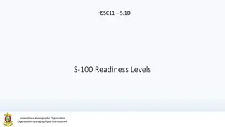
Test Plan Test Date Progress Prerequisite Matlab/Simulink Control Testing Nov 29th Complete None Component Testing Jan 17th In Progress Hardware acquired Feb 8th In Progress Matlab/Simulink Testing Complete Software Implementation Working SITL Testing March 7th Future Work SITL Testing Majority Complete Component Testing Complete Power Model Testing March 11th Future Work Can be concurrent with Power Model Testing Flight Test Schedule 19
Functional Requirements FR-01 The total flyaway cost for flight controller hardware, flight controller software, and a ground station shall be based on current day consumer level UAS flight hardware costs to enable ease of purchase and replacement by smaller organizations. FR-02 The UAS software shall optimize flight trajectory for improved endurance and energy use. FR-03 The UAS shall adhere to FAA guidelines outlined in 14 CFR Part 107, SMALL UNMANNED AIRCRAFT SYSTEMS. FR-04 The flight control system shall be adaptable to a variety of fixed wing air vehicles. FR-05 The UAS shall A) be capable of sustaining an 80% Full Mission Capable rate (RMC) under Instrument Meteorological Conditions (IMC). B) be capable of maintaining a continual 100% standby posture. FR-06 The UAS shall be operable by a single operator for the entire duration of the mission. FR-07 The UAS software shall be capable of a recovery and return mode to maintain the safety of the aircraft. Test Readiness 21
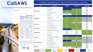
Test Overview Functional Requirement Test Status Component Checks FR-05 Complete Component Controls FR-02 In Progress Unit Testing FR-06, FR-07 In Progress Sub-System FR-02, FR-04, FR-07 In Progress Software in the Loop Hardware Integration FR-06 In Progress FR-02 Planned 3/7 Power Modeling Flight Test - LQT, WARIO, Full FR-02, FR-06, FR-07 Planned 3/11 System FR-05,FR-06 Planned 3/11 Mission Capability Test Readiness 22
Verification: Software In The Loop Testing (SITL) Rationale: Integrated flight software to be tested in isolation from hardware, assess performance of integrated software components Test Fixture: Ardupilot SITL driver with aircraft dynamics model Equipment Needed: Linux Operating System Procedure: a. Configure flight software for desired test scenario. Enable/Disable major project components: i. LQT Control System ii. WARIO Trajectory Algorithm Set simulation parameters i. Wind ii. Dynamics Model Execute Simulation b. c. Risk Reduction: Identify integration incompatibilities between major software components. Test Readiness 23
Verification: Software In The Loop Testing (SITL) Expected/Desired Results: WARIO algorithm adjusts trajectory upon 15odeviation of simulated wind direction within 90 seconds (FR-02) Demonstration of LQT ability to control multiple aircraft dynamics models (FR-04) Verify flight software initiates return to launch upon 30% battery charge (FR-07) Requirement Description FR-02 UAS software shall optimize trajectory for improved endurance and energy. FR-04 The flight control system shall be adaptable to a variety of fixed wing air vehicles. FR-07 The UAS software shall be capable of a recovery and return mode to maintain the safety of the aircraft. Original Wind Direction Direction Updated Wind In Progress Test Readiness 24
Validation: Power Modeling Rationale: Used to predict the power usage of the aircraft from SITL results Validate flight tests and predict how other airframes will perform Reduces risk of aircraft power capabilities during flight Test Fixture: Ardupilot SITL and Matlab Equipment Needed: Multimeter Assembled airframe Requirement Description FR-02 UAS software shall optimize trajectory for improved endurance and energy. Planned for 3/7 Test Readiness 25
Validation: Power Modeling Procedure: a. Measure voltage and current draw at a series of control surface deflection angles. b. Measure voltage and current draw at a series of motor thrust levels. c. Perform regression analysis to develop a power usage model based on control surface deflections and propellor usage. d. Run SITL simulation and use output data to model power usage. Risk Reduction: Allows for the prediction and characterization of power usage to validate flight tests. Expected/Desired Results: 5% increase in endurance Requirement Description FR-02 UAS software shall optimize trajectory for improved endurance and energy. Planned for 3/7 Test Readiness 26
Verification: Flight Testing - WARIO Rationale: Integrated flight software to be tested on hardware in real world conditions. Assess the performance of WARIO separate from the LQT compared to base ardupilot. Test Fixture: Flight Test Facility Equipment Needed: Pixhawk with WARIO implementation Pixhawk with default Ardupilot 2 Flight Units Procedure: a. b. c. d. Load WARIO algorithm onto RALPHIE flight unit. Launch RALPHIE flight unit and Control Flight Unit for simultaneous flight. Initiate Return mode for landing. Download Flight Data from both flight units and compare power usage Risk Reduction: Ensures that the WARIO trajectory algorithm is operating correctly before the full integration flight test. Status: Planned Test Readiness 27
Verification: Flight Testing - LQT Rationale: Integrated flight software to be tested on hardware in real world conditions. Assess the performance of the LQT separate from WARIO compared to base ardupilot. Test Fixture: Test Facility Equipment Needed: Pixhawk with LQT implementation Pixhawk with default Ardupilot 2 Flight Units Procedure: a. b. Load LQT algorithm onto RALPHIE flight unit. Launch RALPHIE flight unit and Control Flight Unit for simultaneous flight. Initiate Return mode for landing. Download Flight Data from both flight units and compare power usage c. d. Risk Reduction: Ensures that the LQT algorithm is operating correctly before the full integration flight test. Status: Planned Test Readiness 28
Verification: Flight Testing - Full Integration Rationale: Integrated flight software to be tested on hardware in real world conditions. Assess the performance of RALPHIE flight software compared to base ardupilot. Test Fixture: Flight Test Facility Equipment Needed: Pixhawk with full RALPHIE flight software Pixhawk with default Ardupilot 2 Flight Units Procedure: a. b. Load RALPHIE FSW onto RALPHIE flight unit. Launch RALPHIE flight unit and Control Flight Unit for simultaneous flight. Initiate Return mode for landing. Download Flight Data from both flight units and compare power usage c. d. Risk Reduction: FAA Part 107 Status: Planned Test Readiness 29
Verification: Flight Testing Full Integration Expected/Desired Results: The Ralphie FSW reduces the power usage for the flight unit by 5% when compared to the default Ardupilot FSW. A Single operator undertakes the mission, from building the RALPHIE flight software to landing The return mode is utilized to return the aircraft to the operator Requirement Description FR-02 UAS software shall optimize trajectory for improved endurance and energy. FR-06 The UAS shall be operable by a single operator for the entire duration of the mission. FR-07 The UAS software shall be capable of a recovery and return mode to maintain the safety of the aircraft. Planned for 3/11 Test Readiness 30
Flight Test Facility Access and Safety Facility Options NOAA Table Mountain Test Facility CU Smead Aerospace/ CU Boulder South Boulder Aeromodler Fields Follow FAA part 107 Guidelines 107.39 Operation over human beings: 107.49 Preflight familiarization, inspection, and actions for aircraft operation. 107.51 Operating limitations for small unmanned aircraft. 107.12 Requirement for a remote pilot certificate with a small UAS rating. Test Readiness 31
Verification: Mission Capability Rationale: Ensure that RALPHIE FSW is capable of being launched at a moments notice once built to achieve mission success. Requirement Description Equipment Needed: Pixhawk with full RALPHIE flight software 1 Flight Unit Ground Station FR-05 The UAS shall A) be capable of sustaining an 80% Full Mission Capable rate (RMC) under Instrument Meteorological Conditions (IMC). B) be capable of maintaining a continual 100% standby posture. Procedure: a. b. c. d. Build software Prime aircraft for launch Launch Aircraft (Concurrent with Flight Testing) Assess mission success FR-06 The UAS shall be operable by a single operator for the entire duration of the mission. Risk Reduction: Reduce risk for general purpose use of flight software Expected/Desired Results: The RALPHIE FSW remains ready for launch and communicating with the ground station after being built and mission parameters are input 100% of the time. The RALPHIE FSW completes mission objectives without error 80% of the time A single operator builds the RALPHIE FSW and input mission parameters Planned for 3/11 Test Readiness 32
Cost Plan System Projected Cost Unit Cost $1,564 x2 Flight Controller Package $233 x2 Air Speed Sensor $49 x1 GPS-RTK Board Ground + Rover $310 x2 GPS-RTK Board Rover $200 x2 Battery $25 x1 Ground Controller $160 x2 Telemetry System $40 Testing $1,424 x4 Airframe $306 x1 FAA License $200 Miscellaneous/Shipping $1,500 Excess $512 Total Used $4,488 Budget 34
Updated Budget Supplier Order Number Parts Purchase Amount Customs Fees Total Status Holybro 22010811402639 $1,355.54 $353.75 $1,709.29 Delivered 22011207575323 $140.03 $0.00 $140.03 Delivered Hobby King 102731726 Airframe (x3) $500.15 $0.00 $500.15 Delivered 102731732 Airframe (x1) $178.89 $0.00 $178.89 Delivered Amazon #114-2944513-7365004 RC Controller $158.99 $0.00 $158.99 Delivered #114-1282445-6371423 $58.19 $0.00 $58.19 Delivered N/a R12DS RadioLink Receiver XT60 Male to Female Extension Adapter $26.99 $0.00 $26.99 Still Processing #112-9936523-7121842 $17.96 $0.00 $17.96 Delivered #112-7654317-9709843 AA Batteries $16.27 $0.00 $16.27 Delivered N/a SD Card $16.96 $0.00 $16.96 Still Processing N/a RC Controller $158.99 $0.00 $158.99 Still Processing FAA Certifications FAA Licenses $350 In Progress $3,332.71 Budget Spent $1,667.29 Remaining Budget: Budget 35
Acknowledgements The team would like to acknowledge: Professor Melvin Rafi Professor John Mah Professor Kathryn Wingate Professor Jelliffe Jackson Professor Eric Frew The PAB and TAs All listed provided lots of support during the senior design process. Their input and feedback has helped guide us to our current design Closing Slides 36
Questions? Closing Slides 37
Highway Analogy How would you increase fuel efficiency while driving a car on a highway? 1. How do we choose a lane on the highway? (Trajectory Planning) a. Which will be the fastest? b. Most cars? 1. How do we get in the lane efficiently? (Control System) b. How sharp do we want the turns? c. How fast should we drive while making these turns? Backup Slide 39
Levels of Success Area of Success Level 1 Level 2 Level 3 Aircraft meets all FAA requirements outlined in 14 CFR Part 107, SMALL UNMANNED AIRCRAFT SYSTEMS. Aircraft has manually override of autonomous control and can be manually controlled. Safety - - Cost Flyaway cost for a single UAS s electrical system and software shall not exceed $1000. Flyaway cost for a single UAS s electrical system and software shall not exceed $950 Flyaway cost for a single UAS s electrical system and software shall not exceed $900 Flight controller inputs environmental & energy factors. Flight controller accounts for environmental & energy factors. 10% increase in endurance from an off the shelf autonomous flight controller. Endurance The software boot time should not exceed 14 minutes and can be used by a single operator. Software obtains GPS lock and performs pre- flight sensor and controls checks. The software boot time should not exceed 12 minutes and can be used by a single operator. The software boot time should not exceed 10 minutes and can be used by a single operator. Software Initialization/Startup Operator controls the aircraft to mission phase and then fully autonomous in mission phase. Create simulation to test software and controls. Autonomous climb and descent. Autonomy - Stay in the mission area while maximizing power distribution to critical systems only. Use on-board sensors to detect environmental factors in order to optimize energy usage and endurance. Integrated Energy and Mission Management - Backup Slide 40
Nomenclature Inertial Position - x: inertial x position (North) - y: inertial y position (East) - z: inertial z position (Down) Euler Angles - : roll angle - : pitch angle - ?: yaw angle Inertial Velocity - u: inertial velocity component along i - v: inertial velocity component along j - w: inertial velocity component along k Angular Velocity - p: roll rate - q: pitch rate - r: yaw rate Full State Vector: Backup Slide 41
Nomenclature - Elevator - ?e - Deflect up and down and causes rotation along the y axis - Rudder - ?r - Deflect left and right and cause rotation on the z axis - Aileron - ?a - Deflect both up and down and cause rotation along the x axis of the aircraft - Throttle - ?t - Along x axis of aircraft Full Input Vector: Backup Slide 42
Software Integration - Perform wind averaging Maintain and store desired trajectory Update trajectory based on conditions - Interface with AHRS to construct current state vector Retrieve the next desired state vector - Use current/desired state to compute control surface inputs - - - Backup Slide 43
Functional Block Diagram Backup Slide 44
Unit Testing Rationale: Individual modules and functions must be validated before integration Test Fixture: Google Test Suit (GMock) Equipment Needed: Linux Operating System Procedure: a. b. c. Create realistic scenario to test Generate expected result Compare expected results with actual results Risk Reduction: Reduce likelihood of undiscovered low-level software bugs during flight Status: In progress Backup Slide 45
Avionics- Pixhawk 4 (Hardware) Hardware 44mm Processor Speed (MHz) RAM (KB) Operational Temperature Range ( C) Total Weight: 33.3 g 216 512 -40 to 85 Main Processor STM32F765 84mm Sufficient RAM available 60 KB of RAM dedicated to LQT (worst case) Easily able to account for general software Verified via comparison to other FSW 12mm Backup Slide 46
Avionics- Pixhawk 4 (Integration) Port and Sensor Capability Important Interfaces GPS Receiver Module Digital Airspeed Sensor (I2C) RC Receiver SD Card Insert USB Power Module I/O Outputs Integrated Sensors 2 Inertial Measurement Units (IMUs) Barometer Magnetometer Backup Slide 47
Avionics- Power Integration PM07 Power Management Board (PMB) Recommended to be used with the Pixhawk4 Connects the ESC and propulsion system, flight controller Sends information about battery voltage and current consumption UBEC Power Regulator 5V/5A Powers servos Must ensure maximum current draw from servos do not exceed 5A Backup Slide 48
Sensors - GPS Receiver Selected Design: Holybro M8N GPS Module Features: Built in compass Accuracy up to a few meters 18 Hz update rate Protective case Plug and play with Pixhawk Backup Slide 49
Sensors - RTK - GPS Selected Design Sparkfun GPS-RTK Board - NEO-M8P - 2 Features Real Time Kinematics upgrade Positioning accuracy of 1 centimeter Used as a base station to provide correction data Backup Slide 50
Feasibility Analysis: Avionics - Battery (Turnigy) Battery Specifications Capacity 5000mAh Turnigy LiPo Pack 20C Discharge Rate 143 x 51 x 23mm Size 360g Weight Features Lightweight Large capacity Medium discharge rate to ensure motor and system as a whole powering capabilities Backup Slide 51
Coms - Telemetry and Data Communication Wireless Pixhawk 4 has a built in telemetry port that can be used to data transmission during flight SiK Radio($50) can be used to send telemetry data to Mission Planner during flight Wired Pixhawk 4 has a built in SD card(Free) that can store telemetry data, this data can then be loaded and into Mission Planner for analysis Both of these options cost no more than $50 and Ardupilot has created extensive walkthroughs for implementation of both Backup Slide 52


")
")


")
")


")