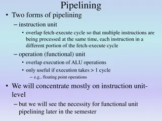
Principles of Pipelining in Computer Architecture
Explore the concept of pipelining in computer architecture through a detailed discussion on the advantages, design efficiency, and stages involved in executing instructions in a pipelined processor. Discover how pipelining improves processing speed and efficiency by keeping all parts of the data path busy simultaneously.

Download Presentation

Please find below an Image/Link to download the presentation.
The content on the website is provided AS IS for your information and personal use only. It may not be sold, licensed, or shared on other websites without obtaining consent from the author. If you encounter any issues during the download, it is possible that the publisher has removed the file from their server.
You are allowed to download the files provided on this website for personal or commercial use, subject to the condition that they are used lawfully. All files are the property of their respective owners.
The content on the website is provided AS IS for your information and personal use only. It may not be sold, licensed, or shared on other websites without obtaining consent from the author.
E N D
Presentation Transcript
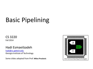
PowerPoint Slides Processor Design The Language of Bits Basic Computer Architecture Prof. Smruti Ranjan Sarangi IIT Delhi Chapter 10: Principles of Pipelining 1
2nd version www.basiccomparch.com Download the pdf of the book videos Slides, software, solution manual Print version (Publisher: WhiteFalcon, 2021) Available on e-commerce sites. The pdf version of the book and all the learning resources can be freely downloaded from the website: www.basiccomparch.com
Outline Overview of Pipelining A Pipelined Data Path Pipeline Hazards Pipeline with Interlocks Forwarding Performance Metrics Interrupts/ Exceptions 3
Up till now . We have designed a processor that can execute all the SimpleRisc Instructions We have look at two styles : With a hardwired control unit Microprogrammed control unit Microprogrammed data path Microassembly Language Microinstructions 4
Designing Efficient Processors Microprogrammed processors are much slower that hardwired processors Even hardwired processors Have a lot of waste !!! We have 5 stages. What is the IF stage doing, when the MA stage is active ? ANSWER : It is idling 5
The Notion of Pipelining Let us go back to the car assembly line Is the engine shop idle, when the paint shop is painting a car ? NO : It is building the engine of another car When this engine goes to the body shop, it builds the engine of another car, and so on . Insight : Multiple cars are built at the same time. A car proceeds from one stage to the next 6
Pipelined Processors inst 5 inst 4 inst 3 inst 2 inst 1 Execute Instruction Fetch (IF) Operand Fetch (OF) Register Write (RW) Memory Access (MA) (EX) The IF, ID, EX, MA, and RW stages process 5 instructions simultaneously Each instruction proceeds from one stage to the next This is known as pipelining 7
Advantages of Pipelining We keep all parts of the data path, busy all the time Let us assume that all the 5 stages do the same amount of work Without pipelining, every T seconds, an instruction completes its execution With pipelining, every T/5 seconds, a new instruction completes its execution 8
Design of a Pipeline Splitting the Data Path We divide the data path into 5 parts : IF, OF, EX, MA, and RW Timing We insert latches (registers) between consecutive stages 4 Latches IF-OF, OF-EX, EX-MA, and MA-RW At the negative edge of a clock, an instruction moves from one stage to the next 9
Pipelined Data Path with Latches Latches Execute Operand Fetch (OF) Instruction Fetch (IF) Register Write (RW) Memory Access (MA) (EX) Add a latch between subsequent stages. Triggered by a negative clock edge 10
The Instruction Packet What travels between stages ? ANSWER : the instruction packet Instruction Packet Instruction contents Program counter All intermediate results Control signals Every instruction moves with its entire state, no interference between instructions 11
Outline Overview of Pipelining A Pipelined Data Path Pipeline Hazards Pipeline with Interlocks Forwarding Performance Metrics Interrupts/ Exceptions 12
IF Stage instruction instruction IF/OF Register Instruction contents saved in the instruction field 13
OF Stage instruction Control unit Immediate and branch target control op2 branchTarget instruction A, B ALU Operands, op2 (store operand), control (set of all control signals) 14
EX Stage control pc op2 A B OF-EX instruction branchTarget aluSignals flags isBeq isBgt isUBranch 0 1 Branch unit ALU isRet branchPC ?ags isBranchTaken control EX-MA pc op2 aluResult instruction aluResult result of the ALU Operation op2, control, pc, instruction (passed from OF-EX) 15
MA Stage control pc op2 aluResult instruction EX-MA mdr isLd mar Data memory Memory unit isSt MA-RW control pc aluResult ldResult instruction ldResult result of the load operation aluResult, control, pc, instruction (passed from EX-MA) 16
RW Stage control instruction pc aluResult ldResult 4 isLd 01 00 isWb 10 isCall E Register file rd 0 A D E enable 1 ra(15) data address data A D 17
1 pc + 4 0 pc instruction Instruction memory pc instruction rd rs2 rs1 ra(15) isSt isRet 0 1 0 1 Control unit reg data Register file op2 Immediate and branch target op1 isWb immx isImmediate 0 1 control pc op2 branchTarget A B instruction aluSignals flags isBeq isBgt isUBranch 0 Branch unit 1 ALU isRet isBranchTaken control pc op2 aluResult instruction isLd mdr mar Data memory Memory unit isSt DRAFT data control pc aluResult instruction ldResult 4 isLd 01 isWb 00 10 isCall rd 0 C Smruti R. Sarangi <srsarangi@cse.iitd.ac.in> ra(15) 1 18
Abridged Diagram OF-EX MA-RW EX-MA IF-OF Control unit Branch unit Memory unit Register write unit Fetch unit Immediate and branch unit flags Data memory ALU Unit op2 Instruction memory Register file op1 19
Outline Overview of Pipelining A Pipelined Data Path Pipeline Hazards Pipeline with Interlocks Forwarding Performance Metrics Interrupts/ Exceptions 20
Pipeline Hazards Now, let us consider correctness Let us introduce a new tool Pipeline Diagram Clock cycles 5 6 8 9 4 7 2 3 1 2 3 1 IF [1]: add r1, r2, r3 2 3 1 OF 2 3 1 [2]: sub r4, r5, r6 EX 2 3 1 MA [3]: mul r8, r9, r10 2 3 1 RW 21
Rules for Constructing a Pipeline Diagram It has 5 rows One per each stage The rows are named : IF, OF, EX, MA, and RW Each column represents a clock cycle Each cell represents the execution of an instruction in a stage It is annotated with the name(label) of the instruction Instructions proceed from one stage to the next across clock cycles 22
Example Clock cycles 5 6 8 9 4 7 2 3 1 2 3 1 IF [1]: add r1, r2, r3 1 2 3 OF 2 3 1 [2]: sub r4, r2, r5 EX 2 3 1 MA [3]: mul r5, r8, r9 2 3 1 RW 23
Data Hazards clock cycles 5 6 8 9 4 7 2 3 1 IF 2 1 [1]: add r1, r2, r3 2 OF 1 2 [2]: sub r3, r1, r4 EX 1 1 2 MA 2 RW 1 Instruction 2 will read incorrect values !!! 24
Data Hazard Definition: A hazard is defined as the possibility of erroneous execution of an instruction in a pipeline. A data hazard represents the possibility of erroneous execution because of the unavailability of data, or the availability of incorrect data. This situation represents a data hazard In specific, it is a RAW (read after write) hazard The earliest we can dispatch instruction 2, is cycle 5 25
Other Types of Data Hazards Our pipeline is in-order Definition: In an in-order pipeline (such as ours), a preceding instruction is always ahead of a succeeding instruction in the pipeline. Modern processors however use out-of-order pipelines that break this rule. It is possible for later instructions to execute before earlier instructions. We will only have RAW hazards in our pipeline. Out-of-order pipelines can have WAR and WAW hazards 26
WAW Hazards [1]: add r1, r2, r3 [2]: sub r1, r4, r3 Instruction [2] cannot write the value of r1, before instruction [1] writes to it, will lead to a WAW hazard 27
WAR Hazards [1]: add r1, r2, r3 [2]: add r2, r5, r6 Instruction [2] cannot write the value of r2, before instruction [1] reads it will lead to a WAR hazard 28
Control Hazards [1]: beq .foo [2]: mov r1, 4 [3]: add r2, r4, r3 ... ... .foo: [100]: add r4, r1, r2 If the branch is taken, instructions [2] and [3], might get fetched, incorrectly 29
Control Hazard Pipeline Diagram Clock cycles 5 6 8 9 4 7 2 3 1 2 3 1 IF [1]: beq .foo 2 3 1 OF 2 3 1 [2]: mov r1, 4 EX 2 3 1 MA [3]: add r2, r4, r3 2 3 1 RW The two instructions fetched immediately after a branch instruction might have been fetched incorrectly. 30
Control Hazards The two instructions fetched immediately after a branch instruction might have been fetched incorrectly. These instructions are said to be on the wrong path A control hazard represents the possibility of erroneous execution in a pipeline because instructions in the wrong path of a branch can possibly get executed and save their results in memory, or in the register file 31
Structural Hazards A structural hazard may occur when two instructions have a conflict on the same set of resources in a cycle Example : Assume that we have an add instruction that can read one operand from memory add r1, r2, 10[r3] 32
Structural Hazards - II [1]: st r4, 20[r5] [2]: sub r8, r9, r10 [3]: add r1, r2, 10[r3] This code will have a structural hazard [3] tries to read 10[r3] (MA unit) in cycle 4 [1] tries to write to 20[r5] (MA unit) in cycle 4 Does not happen in our pipeline 33
Solutions in Software Data hazards Insert nop instructions, reorder code [1]: add r1, r2, r3 [2]: sub r3, r1, r4 [1]: add r1, r2, r3 [2]: nop [3]: nop [4]: nop [5]: sub r3, r1, r4 34
Code Reordering add r1, r2, r3 add r8, r5, r6 add r10, r11, r12 nop add r4, r1, 3 add r9, r8, r5 add r13, r10, 2 add r1, r2, r3 add r4, r1, 3 add r8, r5, r6 add r9, r8, r5 add r10, r11, r12 add r13, r10, 2 35
Control Hazards Trivial Solution : Add two nop instructions after every branch Better solution : Assume that the two instructions fetched after a branch are valid instructions These instructions are said to be in the delay slots Such a branch is known as a delayed branch 36
Example with 2 Delay Slots b .foo add r1, r2, r3 add r4, r5, r6 add r8, r9, r10 add r1, r2, r3 add r4, r5, r6 b .foo add r8, r9, r10 The compiler transfers instructions before the branchto the delay slots. If it cannot find 2 valid instructions, it inserts nops. 37
Outline Overview of Pipelining A Pipelined Data Path Pipeline Hazards Pipeline with Interlocks Forwarding Performance Metrics Interrupts/ Exceptions 38
Why interlocks ? We cannot always trust the compiler to do a good job, or even introduce nop instructions correctly. Compilers now need to be tailored to specific hardware. We should ideally not expose the details of the pipeline to the compiler (might be confidential also) Hardware mechanism to enforce correctness interlock 39
Two kinds of Interlocks Data-Lock Do not allow a consumer instruction to move beyond the OF stage till it has read the correct values. Implication : Stall the IF and OF stages. Branch-Lock We never execute instructions in the wrong path. The hardware needs to ensure both these conditions. 40
Comparison between Software and Hardware Attribute Portability Software Limited to a specific processor Hardware(withinterlocks) Programs can be run on any processor irrespective of the nature of the pipeline Need to stall the pipeline for 2 cycles in our design Branches Possible to have no performance penalty, by using delay slots Possible to eliminate them through code scheduling Highlydependent on the nature of the program RAW hazards Need to stall the pipeline Performance The basic version of a pipeline with interlocks is expected to be slower than the version that relies on software 41
Conceptual Look at Pipeline with Interlocks [1]: add r1, r2, r3 [2]: sub r4, r1, r2 We have a RAW hazard We need to stall, instruction [2] at the OF stage for 3 cycles. We need to keep sending nop instructions to the EX stage during these 3 cycles 42
Example Clock cycles bubble 5 6 8 9 4 7 2 3 1 2 IF 1 [1]: add r1, r2, r3 2 2 OF 1 2 2 [2]: sub r4, r1, r2 2 1 EX 2 1 MA 2 1 RW 43
A Pipeline Bubble A pipeline bubble is inserted into a stage, when the previous stage needs to be stalled It is a nop instruction To insert a bubble Create a nop instruction packet OR, Mark a designated bubble bit to 1 44
Bubbles in the Case of a Branch Instruction Clock cycles bubble 5 6 8 9 4 7 2 3 1 [1]: beq. foo [2]: add r1, r2, r3 [3]: sub r4, r5, r6 .... .... .foo: [4]: add r8, r9, r10 2 IF 3 4 1 2 1 4 OF 4 1 EX 1 4 MA 4 1 RW 45
Control Hazards and Bubbles We know that an instruction is a branch in the OF stage When it reaches the EX stage and the branch is taken, let us convert the instructions in the IF, and OF stages to bubbles Ensures the branch-lock condition 46
Ensuring the Data-Lock Condition When an instruction reaches the OF stage, check if it has a conflict with any of the instructions in the EX, MA, and RW stages If there is no conflict, nothing needs to be done Otherwise, stall the pipeline (IF and OF stages only) 47
Algorithm 5: Algorithm to detect conflicts between instructions Data: instructions, [A], and [B] Result: conflict exists (true), no conflict (false) if [A].opcode (nop,b,beq,bgt,call) then /* Does not read from any register return false end if [B].opcode (nop, cmp, st, b, beq, bgt, ret) then /* Does not write to any register return false end /* Set the sources src1 [A].rs1 src2 [A].rs2 if [A].opcode = st then src2 [A].rd end if [A].opcode = ret then src1 ra end hasSrc1 true if ([A] (not, mov)) hasSrc1 false */ */ */ 48
dest [B].rd if [B].opcode = call then dest ra end /* Check the second operand to see if it is a register hasSrc2 true if [A].opcode ( st) then if [A].I = 1 then hasSrc2 false end end /* Detect conflicts */ if (hasSrc1 = true) and (src1 = dest) then return true end else if (hasSrc2 = true) and (src2 = dest) then return true end return false */ */ 49
How to Stall a Pipeline ? Disable the write functionality of : The IF-OF register and the Program Counter (PC) To insert a bubble Write a bubble (nop instruction) into the OF-EX register 50