Overview of Assemblers in Information Technology
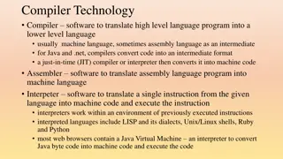
Explore the role of assemblers in converting mnemonic operation codes to machine language, assigning addresses to symbolic labels, and more. Learn about basic assembler functions, machine-dependent and machine-independent features, assembler design options, and assembler directives. Dive into the process of converting codes to machine language, building machine instructions, handling data constants, and writing object programs. Witness examples of assembler functions and instruction assembly processes.

Download Presentation

Please find below an Image/Link to download the presentation.
The content on the website is provided AS IS for your information and personal use only. It may not be sold, licensed, or shared on other websites without obtaining consent from the author.If you encounter any issues during the download, it is possible that the publisher has removed the file from their server.
You are allowed to download the files provided on this website for personal or commercial use, subject to the condition that they are used lawfully. All files are the property of their respective owners.
The content on the website is provided AS IS for your information and personal use only. It may not be sold, licensed, or shared on other websites without obtaining consent from the author.
E N D
Presentation Transcript
UNIT I Assemblers DEPARTMENT OF INFORMATION TECHNOLOGY R.KARTHIGAICHELVI 1
Role of Assembler Object Source Assembler Linker Code Program Executable Code Loader 2
Chapter 2 -- Outline Basic Assembler Functions Machine-dependent Assembler Features Machine-independent Assembler Features Assembler Design Options 3
Introduction to Assemblers Fundamental functions translating mnemonic operation codes to their machine language equivalents assigning machine addresses to symbolic labels Machine dependency different machine instruction formats and codes 4
Example Program (Fig. 2.1) Purpose reads records from input device (code F1) copies them to output device (code 05) at the end of the file, writes EOF on the output device, then RSUB to the operating system 5
Example Program (Fig. 2.1) Data transfer (RD, WD) a buffer is used to store record buffering is necessary for different I/O rates the end of each record is marked with a null character (0016) the end of the file is indicated by a zero-length record Subroutines (JSUB, RSUB) RDREC, WRREC save link register first before nested jump 6
Assembler Directives Pseudo-Instructions Not translated into machine instructions Providing information to the assembler Basic assembler directives START END BYTE WORD RESB RESW 7
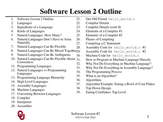
Assemblers functions Convert mnemonic operation codes to their machine language equivalents Convert symbolic operands to their equivalent machine addresses Build the machine instructions in the proper format Convert the data constants to internal machine representations Write the object program and the assembly listing 8
Example of Instruction Assemble 549039 STCH BUFFER,X 8 1 x 15 opcode address m (54)16 1 (001)2 (039)16 Forward reference 9
Difficulties: Forward Reference Forward reference: reference to a label that is defined later in the program. Loc Label Operator Operand 1000 FIRST STL RETADR 1003 1012 1033 CLOOP JSUB J RESW RDREC CLOOP 1 RETADR 10
Two Pass Assembler Pass 1 Assign addresses to all statements in the program Save the values assigned to all labels for use in Pass 2 Perform some processing of assembler directives Pass 2 Assemble instructions Generate data values defined by BYTE, WORD Perform processing of assembler directives not done in Pass 1 Write the object program and the assembly listing 11
Two Pass Assembler Read from input line LABEL, OPCODE, OPERAND Source program Intermediate file Object codes Pass 1 Pass 2 OPTAB SYMTAB SYMTAB 12
Data Structures Operation Code Table (OPTAB) Symbol Table (SYMTAB) Location Counter(LOCCTR) 13
OPTAB (operation code table) Content menmonic, machine code (instruction format, length) etc. Characteristic static table Implementation array or hash table, easy for search 14
SYMTAB (symbol table) Content label name, value, flag, (type, length) etc. Characteristic dynamic table (insert, delete, search) Implementation hash table, non-random keys, hashing function COPY FIRST CLOOP ENDFIL EOF THREE ZERO RETADR LENGTH BUFFER RDREC 1000 1000 1003 1015 1024 102D 1030 1033 1036 1039 2039 15
Object Program Header Col. 1 H Col. 2~7 Program name Col. 8~13 Starting address (hex) Col. 14-19 Length of object program in bytes (hex) Text Col.1 T Col.2~7 Starting address in this record (hex) Col. 8~9 Length of object code in this record in bytes (hex) Col. 10~69Object code (69-10+1)/6=10 instructions End Col.1 E Col.2~7 Address of first executable instruction (hex) (END program_name) 16
Fig. 2.3 H COPY 001000 00107A T 001000 1E 141033 482039 001036 281030 301015 482061 ... T 00101E 15 0C1036 482061 081044 4C0000 454F46 000003 000000 T 002039 1E 041030 001030 E0205D 30203F D8205D 281030 T 002057 1C 101036 4C0000 F1 001000 041030 E02079 302064 T 002073 07 382064 4C0000 05 E 001000 17
Homework #1 SUM FIRST START LDX LDA ADD TIX JLT STA RSUB RESW RESW WORD RESW END 4000 ZERO ZERO TABLE,X COUNT LOOP TOTAL LOOP TABLE COUNT ZERO TOTAL 2000 1 0 1 FIRST E En nd d o of f S Se ec c 2 2- -1 1 18
Assembler Design Machine Dependent Assembler Features instruction formats and addressing modes program relocation Machine Independent Assembler Features literals symbol-defining statements expressions program blocks control sections and program linking 19
Machine-dependent Assembler Features Sec. 2-2 Instruction formats and addressing modes Program relocation 20
Instruction Format and Addressing Mode SIC/XE PC-relative or Base-relative addressing: Indirect addressing: Immediate addressing: Extended format: Index addressing: register-to-register instructions larger memory -> multi-programming (program allocation) Example program Figure 2.5 op m op @m op #c +op m op m,x 21
Translation Register translation register name (A, X, L, B, S, T, F, PC, SW) and their values (0,1, 2, 3, 4, 5, 6, 8, 9) preloaded in SYMTAB Address translation Most register-memory instructions use program counter relative or base relative addressing Format 3: 12-bit address field base-relative: 0~4095 pc-relative: -2048~2047 Format 4: 20-bit address field 22
PC-Relative Addressing Modes PC-relative 10 0000 FIRST STL RETADR 17202D op(6) n I x b p e disp(12) (14)16 1 1 0 0 1 0 displacement= RETADR - PC = 30-3 = 2D 0017 J (02D) 16 40 CLOOP 3F2FEC op(6) n I x b p e disp(12) (3C)16 1 1 0 0 1 0 (FEC) 16 displacement= CLOOP-PC= 6 - 1A= -14= FEC 23
Base-Relative Addressing Modes Base-relative base register is under the control of the programmer 12 LDB 13 BASE LENGTH 160 104E STCH BUFFER, X #LENGTH 57C003 op(6) n I x b p e disp(12) ( 54 )16 1 1 1 1 0 0 (54) 1 1 1 0 1 0 0036-1051= -101B16 displacement= BUFFER - B = 0036 - 0033 = 3 NOBASE is used to inform the assembler that the contents of the base register no longer be relied upon for addressing ( 003 ) 16 24
Immediate Address Translation Immediate addressing 55 0020 op(6) LDA #3 010003 n I x b p e disp(12) ( 00 )16 0 1 0 0 0 0 ( 003 ) 16 133 103C op(6) +LDT #4096 n I x b p e 75101000 disp(20) ( 74 )16 0 1 0 0 0 1 ( 01000 ) 16 25
Immediate Address Translation (Cont.) Immediate addressing 12 op(6) 0003 LDB #LENGTH disp(12) 69202D n I x b p e ( 68)16 0 1 0 0 1 0 ( 68)16 ( 02D ) 16 0 1 0 0 0 0 ( 033)16 690033 the immediate operand is the symbol LENGTH the address of this symbol LENGTH is loaded into register B LENGTH=0033=PC+displacement=0006+02D if immediate mode is specified, the target address becomes the operand 26
Indirect Address Translation Indirect addressing target addressing is computed as usual (PC- relative or BASE-relative) only the n bit is set to 1 70 002A J @RETADR 3E2003 op(6) n I x b p e disp(12) ( 3C )16 1 0 0 0 1 0 TA=RETADR=0030 TA=(PC)+disp=002D+0003 ( 003 ) 16 27
Program Relocation Example Fig. 2.1 Absolute program, starting address 1000 e.g. 55 101B Relocate the program to 2000 e.g. 55 101B Each Absolute address should be modified Example Fig. 2.5: Except for absolute address, the rest of the instructions need not be modified not a memory address (immediate addressing) PC-relative, Base-relative The only parts of the program that require modification at load time are those that specify direct addresses LDA THREE 00102D LDA THREE 00202D 28
Example 29
Relocatable Program Modification record Col 1 M Col 2-7 Starting location of the address field to be modified, relative to the beginning of the program Col 8-9 length of the address field to be modified, in half- bytes 30
Object Code E En nd d o of f S Se ec c 2 2- -2 2 31
Machine-Independent Assembler Features Literals Symbol Defining Statement Expressions Program Blocks Control Sections and Program Linking 32
Literals Design idea Let programmers to be able to write the value of a constant operand as a part of the instruction that uses it. This avoids having to define the constant elsewhere in the program and make up a label for it. Example e.g. 45 001A ENDFILLDA 93 LTORG 002D * =C EOF e.g. 215 1062 WLOOP 032010 =C EOF 454F46 TD =X 05 E32011 33
Literals vs. Immediate Operands Immediate Operands The operand value is assembled as part of the machine instruction e.g. 55 0020 Literals The assembler generates the specified value as a constant at some other memory location e.g. 45 001A ENDFILLDA Compare (Fig. 2.6) e.g. 45 001A ENDFIL 80 002D EOF LDA #3 010003 032010 =C EOF LDA BYTE C EOF 454F46 EOF 032010 34
Literal - Implementation (1/3) Literal pools Normally literals are placed into a pool at the end of the program see Fig. 2.10 (END statement) In some cases, it is desirable to place literals into a pool at some other location in the object program assembler directive LTORG reason: keep the literal operand close to the instruction 35
Literal - Implementation (2/3) Duplicate literals e.g. 215 e.g. 230 The assemblers should recognize duplicate literals and store only one copy of the specified data value Comparison of the defining expression Same literal name with different value, e.g. LOCCTR=* Comparison of the generated data value The benefits of using generate data value are usually not great enough to justify the additional complexity in the assembler 1062 WLOOP 106B TD WD =X 05 =X 05 36
Literal - Implementation (3/3) LITTAB literal name, the operand value and length, the address assigned to the operand Pass 1 build LITTAB with literal name, operand value and length, leaving the address unassigned when LTORG statement is encountered, assign an address to each literal not yet assigned an address Pass 2 search LITTAB for each literal operand encountered generate data values using BYTE or WORD statements generate modification record for literals that represent an address in the program 37
Symbol-Defining Statements Labels on instructions or data areas the value of such a label is the address assigned to the statement Defining symbols symbolEQU value value can be: constant, expression making the source program easier to understand no forward reference other symbol, 38
Symbol-Defining Statements Example 1 MAXLEN EQU +LDT #MAXLEN 4096 +LDT #4096 Example 2 BASE COUNT EQU INDEX EQU R3 Example 3 MAXLEN EQU R1 R2 EQU BUFEND-BUFFER 39
ORG (origin) Indirectly assign values to symbols Reset the location counter to the specified value ORG value Value can be: constant, expression No forward reference Example SYMBOL: 6bytes VALUE: 1word FLAGS: 2bytes LDA VALUE, X other symbol, SYMBOL VALUE FLAGS STAB (100 entries) . . . . . . . . . 40
ORG Example Using EQU statements STAB RESB 1100 SYMBOL VALUE EQU FLAG EQU Using ORG statements STAB RESB 1100 ORG SYMBOL VALUE RESW 1 FLAGS RESB 2 ORG EQU STAB+6 STAB+9 STAB STAB RESB 6 STAB+1100 41
Expressions Expressions can be classified as absolute expressions or relative expressions MAXLEN BUFEND and BUFFER both are relative terms, representing addresses within the program However the expression BUFEND-BUFFER represents an absolute value When relative terms are paired with opposite signs, the dependency on the program starting address is canceled out; the result is an absolute value EQU BUFEND-BUFFER 42
SYMTAB None of the relative terms may enter into a multiplication or division operation Errors: BUFEND+BUFFER 100-BUFFER 3*BUFFER The type of an expression keep track of the types of all symbols defined in the program Symbol RETADR BUFFER BUFEND MAXLEN Type R R R A Value 30 36 1036 1000 43
Example 2.9 Name COPY FIRST CLOOP ENDFIL RETADR LENGTH BUFFER BUFEND MAXLEN RDREC RLOOP EXIT INPUT WREC WLOOP Value SYMTAB LITTAB C'EOF' X'05' 0 0 6 454F46 3 1 002D 1076 05 1A 30 33 36 1036 1000 1036 1040 1056 105C 105D 1062 44
Program Blocks Program blocks refer to segments of code that are rearranged within a single object program unit USE [blockname] At the beginning, statements are assumed to be part of the unnamed (default) block If no USE statements are included, the entire program belongs to this single block Example: Figure 2.11 Each program block may actually contain several separate segments of the source program 45
Program Blocks - Implementation Pass 1 each program block has a separate location counter each label is assigned an address that is relative to the start of the block that contains it at the end of Pass 1, the latest value of the location counter for each block indicates the length of that block the assembler can then assign to each block a starting address in the object program Pass 2 The address of each symbol can be computed by adding the assigned block starting address and the relative address of the symbol to that block 46
Figure 2.12 Each source line is given a relative address assigned and a block number Block name Block number (default) CDATA CBLKS Address 0000 0066 0071 Length 0066 000B 1000 0 1 2 For absolute symbol, there is no block number line 107 Example 20 0006 0 LDA LENGTH=(Block 1)+0003= 0066+0003= 0069 LOCCTR=(Block 0)+0009= 0009 LENGTH 032060 47
Program Readability Program readability No extended format instructions on lines 15, 35, 65 No needs for base relative addressing (line 13, 14) LTORG is used to make sure the literals are placed ahead of any large data areas (line 253) Object code It is not necessary to physically rearrange the generated code in the object program see Fig. 2.13, Fig. 2.14 48
Control Sections and Program Linking Control Sections are most often used for subroutines or other logical subdivisions of a program the programmer can assemble, load, and manipulate each of these control sections separately instruction in one control section may need to refer to instructions or data located in another section because of this, there should be some means for linking control sections together Fig. 2.15, 2.16 49
External Definition and References External definition EXTDEF EXTDEF names symbols that are defined in this control section and may be used by other sections External reference EXTREF name [,name] EXTREF names symbols that are used in this control section and are defined elsewhere Example 15 0003 CLOOP +JSUB RDREC 160 0017 +STCH BUFFER,X 190 0028 MAXLEN WORD BUFEND-BUFFER name [, name] 4B100000 57900000 000000 50


")
")


")
")


")


")
")
")


")