Optimal Op-Amp Circuit Designs for Precise Signal Amplification
Explore different op-amp configurations for signal amplification and learn how to optimize them for specific input signal ranges, ensuring minimal distortion and overshoot. Find solutions to achieve the desired 0 to 10V output with various input signal conditions and power supply voltages.

Download Presentation

Please find below an Image/Link to download the presentation.
The content on the website is provided AS IS for your information and personal use only. It may not be sold, licensed, or shared on other websites without obtaining consent from the author. Download presentation by click this link. If you encounter any issues during the download, it is possible that the publisher has removed the file from their server.
E N D
Presentation Transcript
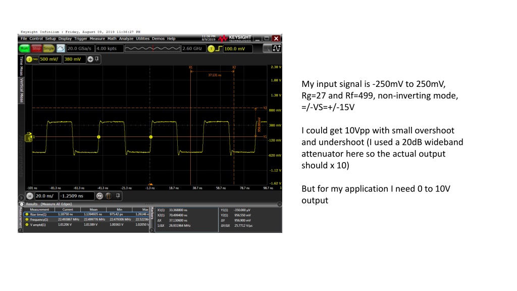
My input signal is -250mV to 250mV, Rg=27 and Rf=499, non-inverting mode, =/-VS=+/-15V I could get 10Vpp with small overshoot and undershoot (I used a 20dB wideband attenuator here so the actual output should x 10) But for my application I need 0 to 10V output
My input signal is 0mV to 500mV, Rg=27 and Rf=499, non-inverting mode, =/- VS=+/-15V The amplified signal has been distorted
Here VS=20V and VS=-10V The amplified signal has huge overshoot and undershoot
Here VS=20V and VS=-20V The amplified signal has been improved a bit but this may not be good for the opamp to operate