Networked DC/AC Power Monitor for SMART Lab

NETWORKED DC/AC POWER MONITOR
Freescale – Thread IoT
GROUP 2.4
ALAN H HENDERSON
PROJECT MANAGER
BRIAN SAMUELS
HARDWARE ENGINEER
LAHCEN BOUHOU
HARDWARE ENGINEER
KELSEY KING
SOFTWARE ENGINEER
SAMUEL CHABOT
SOFTWARE ENGINEER
Project Description
Goal:
Design a networked solution to monitor AC and DC power for use on the solar
panel and
wind turbine setup for the SMART Lab
Scope:
Design and implement a prototype
•
Flexibility to sense AC and DC voltage and current experienced in the SMART Lab
•
Data transmission using Thread network
•
Power Management
Stretch Goals
•
Design a minimal PCB layout
•
Deploy a full scale
network
•
GUI to analyze power production in the SMART lab
SMART Lab Schematic
6750 W System
Three 1520 W Systems
•
Flexible design to account for all
SMART Lab devices
•
87 locations for sensors
o
53 solar panels
o
9 wind turbines
o
18 8D sealed lead-acid storage
batteries
o
7 DC/AC inverters
•
Each will measure voltage and current
o
174 signals to transmit via
Thread
Design Constraints
•
Versatile design for universal pairing with
various SMART Lab elements
o
Solar panels
o
Wind turbines
o
Batteries
o
Inverters
•
IEEE 802.15.4 compatibility required
•
Lowest possible cost due to future mass
production
•
Weather-proofing
•
Sense DC/AC voltage:
o
Voltage range between 0V-300V max
o
Resolution has to be 0.1 V
o
Sample Frequency 1Hz
o
Batch frequency between 1to 10 min
•
Sense DC/AC current:
o
The current range between 0A -150 A max
o
Resolution has to be 0.05A
o
Sample Frequency 1Hz
o
Batch frequency between 1to 10 min
Hardware Design Details: Sensing
•
The sensing circuits can measure AC and DC
voltages and currents
o
3 phase AC
o
Frequency will be measured via a zero crossing
strategy at the software level
o
Phase angle can also be measured and will also
occur at the software level
•
Voltage sensing via a voltage division resistive
network and an operational
amplifier
o
L
arge resistances to limit current
•
Current sensing utilizes a ACS759KCB-150B-PFF-T
hall
effect IC
o
This device is rated to read ±150A
bidirectional
o
Outputs
0 to 3.3V, where -150A equals 0V and
+150A equals 3.3V
Hardware Design Details: Power
•
Power will initially be provided via a battery pack but
parasitic power is being pursued.
o
On a board level using another resistive network and a
voltage regulation circuit. This will result in significantly
increased costs and a more complicated PCB.
o
A single DC source connected to the main battery pack
for the entire solar and wind power array. This will be
easier but it will also entail routing low voltage DC
wires back out to every sensor. This negates some of
the benefits of having a wireless system.
Hardware
Solution
•
Circuit required to both reduce and
offset the voltage to a range of 0 to 3.3V.
•
Figure shows utilization of operational
amplifier with negative feedback loop
•
A voltage divider used to reduce
onboard power supply to offset the
voltage to the desired range of 0 to 3.3V.
Validation Test Plan
The following cases are tested using the KW24D512-TWR board as a prototype
:
Sense DC/AC voltage:
•
Voltage range between 0V-300V max
•
Resolution has to be 0.1V
•
Sample Frequency 1Hz
•
Batch frequency between 1 to 10 min
Sense
DC/AC
current:
•
The current range between 0A -150A max
•
Resolution has to be 0.05A
•
Sample Frequency 1Hz
•
Batch frequency between 1 to 10 min
Data Transmission verified using Proximetry Agent
Thread Network
•
Thread group established in July 2014
•
IPv6-based
•
Self-healing mesh networking protocol
•
IEEE 802.15.4 standard transmission hardware
compatible
•
Support for up to 250 devices
•
Texas State University Thread network deployed
April 2015
•
Thread updates scheduled will include capability
to transmit multiple data types
Proximetry Agent
•
Web-based interface coupled with Thread
•
Displays real-time network information
o
Routers
o
Devices
o
Access points
o
Status of nodes
•
Responsible for receiving and charting
transmitted data
•
Secure, location-independent access via web
login
Proximetry
Data Monitoring
•
Real-time data view
•
Time axis expandable from five
minutes to one week
•
Multiple users able to concurrently
view data
•
Future updates will allow for data
types to be displayed at once
Prototype Budget
T
o
t
a
l
:
$
4
3
.
0
7
$
6
.
0
7
Impact
•
Our solution provides a wireless
flexible data collection tool:
o
AC/DC
o
Current/Voltage
o
Wide ranges
•
Monitor the Efficiency of the
SMART Lab
•
Other Possible Applications:
o
DC grid data collection and
evaluation
•
Safety:
o
High voltages and currents
•
Ethical:
o
With the evolution of
connected devices, security
becomes an inherent concern
•
Environmental:
o
Low power characteristics
mean efficient operation
o
Materials can be sourced
environmentally-friendly
Future Plans
•
New iterations of the Thread networking protocol
o
multiple data types
o
generated software hooks/constructed hardware
-
3-phase AC voltage, current, and power
-
Minimal PCB layout can be expanded upon
-
Prototype can be duplicated and deployed across the desired
87 locations in the SMART Lab to take full advantage of the
power monitoring solution.
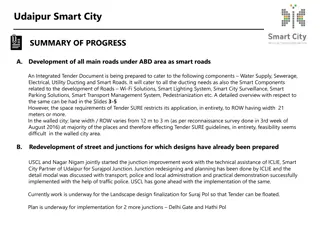
Design a networked solution to monitor AC and DC power on solar panel and wind turbine setups in the SMART Lab. The project aims to implement a prototype with flexibility to sense voltage and current, data transmission using Thread network, and power management stretch goals. The design constraints require versatile design, IEEE 802.15.4 compatibility, and lowest possible cost for future mass production.

Download Presentation

Please find below an Image/Link to download the presentation.
The content on the website is provided AS IS for your information and personal use only. It may not be sold, licensed, or shared on other websites without obtaining consent from the author.If you encounter any issues during the download, it is possible that the publisher has removed the file from their server.
You are allowed to download the files provided on this website for personal or commercial use, subject to the condition that they are used lawfully. All files are the property of their respective owners.
The content on the website is provided AS IS for your information and personal use only. It may not be sold, licensed, or shared on other websites without obtaining consent from the author.
E N D
Presentation Transcript
NETWORKED DC/AC POWER MONITOR Freescale Thread IoT GROUP 2.4 ALAN H HENDERSON BRIAN SAMUELS LAHCEN BOUHOU KELSEY KING SAMUEL CHABOT PROJECT MANAGER HARDWARE ENGINEER HARDWARE ENGINEER SOFTWARE ENGINEER SOFTWARE ENGINEER
Project Description Goal: Design a networked solution to monitor AC and DC power for use on the solar panel and wind turbine setup for the SMART Lab Scope: Design and implement a prototype Flexibility to sense AC and DC voltage and current experienced in the SMART Lab Data transmission using Thread network Power Management Stretch Goals Design a minimal PCB layout Deploy a full scale network GUI to analyze power production in the SMART lab
SMART Lab Schematic Flexible design to account for all SMART Lab devices 6750 W System 87 locations for sensors o 53 solar panels o 9 wind turbines o 18 8D sealed lead-acid storage batteries o 7 DC/AC inverters Each will measure voltage and current o 174 signals to transmit via Thread Three 1520 W Systems
Design Constraints Versatile design for universal pairing with various SMART Lab elements Sense DC/AC voltage: o Voltage range between 0V-300V max o Resolution has to be 0.1 V o Sample Frequency 1Hz o Batch frequency between 1to 10 min o Solar panels o Wind turbines o Batteries Sense DC/AC current: o The current range between 0A -150 A max o Resolution has to be 0.05A o Sample Frequency 1Hz o Batch frequency between 1to 10 min o Inverters IEEE 802.15.4 compatibility required Lowest possible cost due to future mass production Weather-proofing
Hardware Design Details: Sensing The sensing circuits can measure AC and DC voltages and currents o 3 phase AC o Frequency will be measured via a zero crossing strategy at the software level o Phase angle can also be measured and will also occur at the software level Voltage sensing via a voltage division resistive network and an operational amplifier o Large resistances to limit current Current sensing utilizes a ACS759KCB-150B-PFF-T hall effect IC o This device is rated to read 150A bidirectional o Outputs 0 to 3.3V, where -150A equals 0V and +150A equals 3.3V
Hardware Design Details: Power Power will initially be provided via a battery pack but parasitic power is being pursued. o On a board level using another resistive network and a voltage regulation circuit. This will result in significantly increased costs and a more complicated PCB. o A single DC source connected to the main battery pack for the entire solar and wind power array. This will be easier but it will also entail routing low voltage DC wires back out to every sensor. This negates some of the benefits of having a wireless system.
Hardware Solution Circuit required to both reduce and offset the voltage to a range of 0 to 3.3V. Figure shows utilization of operational amplifier with negative feedback loop A onboard power supply to offset the voltage to the desired range of 0 to 3.3V. voltage divider used to reduce
Validation Test Plan The following cases are tested using the KW24D512-TWR board as a prototype: Sense DC/AC voltage: Voltage range between 0V-300V max Resolution has to be 0.1V Sample Frequency 1Hz Batch frequency between 1 to 10 min Sense DC/AC current: The current range between 0A -150A max Resolution has to be 0.05A Sample Frequency 1Hz Batch frequency between 1 to 10 min Data Transmission verified using Proximetry Agent
Thread Network Thread group established in July 2014 IPv6-based Self-healing mesh networking protocol IEEE 802.15.4 standard transmission hardware compatible Support for up to 250 devices Texas State University Thread network deployed April 2015 Thread updates scheduled will include capability to transmit multiple data types
Proximetry Agent Web-based interface coupled with Thread Displays real-time network information o Routers o Devices o Access points o Status of nodes Responsible for receiving and charting transmitted data Secure, location-independent access via web login
Proximetry Data Monitoring Real-time data view Time axis expandable from five minutes to one week Multiple users able to concurrently view data Future updates will allow for data types to be displayed at once
Prototype Budget Project Name DC Voltage Project Section Required Total (with spares) Company Cost Each Cost Total Cost 500 Voltage Divider 3 10 Vishay/Mouser $0.19 $1.90 $0.125 Voltage Divider 3 10 Vishay/Mouser $0.12 $1.20 $0.120 AC Voltage Voltage Divider 6 10 Vishay/Mouser $0.19 $1.90 $0.190 Operational Amplifier 3 5 Mouser $0.58 $2.90 $0.266 Input Resistor 3 5 Mouser $0.26 $1.30 $0.180 Feedback Resistor 3 5 Mouser $0.69 $3.45 $0.179 AC/DC Current Current Transducer 3 3 Digi-Key $7.98 $23.94 $4.200 10uF Capacitor 1 2 Mouser $0.56 $1.12 $0.340 0.1uF Capacitor 1 2 Mouser $0.30 $0.60 $0.250 Circuit Protection 3.3V Zener Diodes 14 14 Mouser $0.34 $4.76 $0.188 Freescale Tower Development Board 1 1 Freescale $149.00 (Donated) Elevator Module 1 1 Freescale $39.00 $0.000 (Donated) $6.07 Total: $43.07
Impact Our solution provides a wireless flexible data collection tool: o AC/DC o Current/Voltage o Wide ranges Monitor the Efficiency of the SMART Lab Other Possible Applications: o DC grid data collection and evaluation Safety: o High voltages and currents Ethical: o With the evolution of connected devices, security becomes an inherent concern Environmental: o Low power characteristics mean efficient operation o Materials can be sourced environmentally-friendly
Future Plans New iterations of the Thread networking protocol o multiple data types o generated software hooks/constructed hardware - 3-phase AC voltage, current, and power - Minimal PCB layout can be expanded upon - Prototype can be duplicated and deployed across the desired 87 locations in the SMART Lab to take full advantage of the power monitoring solution.