Network Security
Network Security
CSE 365
– Information Assurance
Spring 2020
Adam Doupé
Arizona State University
http://adamdoupe.com
The Internet Protocol Suite
•
Set of protocols used to transport data
between nodes of a network
•
Also known as the TCP/IP Protocol Suite
•
Based on abstraction and encapsulation
•
Link protocols
•
Internet protocols
•
Transport protocols
•
Application protocols
TCP/IP Layering
TCP
UDP
IP
HTTP
NFS
Hardware Interface
SMTP
DNS
IGMP
ICMP
Physical Layer
ARP
RARP
Link
Internet
Transport
Application
IP Addresses
•
Each host has one or more IP addresses
for each network interface
•
IPv4 addresses are composed of 32 bits
•
Represented in dotted-decimal notation:
149.169.175.207
Classless Inter-Domain Routing
(CIDR)
•
Allocation of large chunks of IP addresses wasted
an enormous number of IP addresses
•
Number of hosts is increasing
•
IPv6 provides a larger address space but adoption
is slow
•
CIDR is an addressing scheme from 1993 for the
Internet which allows for more efficient allocation
of IP addresses
•
The netid/hostid boundary can be placed on any
bit between 13 and 27
–
32 hosts minimum
–
524,288 hosts maximum
Internet Protocol (IP)
•
The IP protocol represents the “glue” of the
Internet
•
The IP protocol provides a connectionless,
unreliable, best-effort datagram delivery service
(delivery, integrity, ordering, non-duplication, and
bandwidth is not guaranteed)
•
IP datagrams can be exchanged between any two
nodes (provided they both have an IP address)
•
For direct communication IP relies on a number of
different lower-level protocols, e.g., Ethernet,
Token Ring, FDDI, RS-232, 802.11
IP Datagram – RFC 791
Version
HL
Service type (TOS)
Header checksum
Identifier
Flags
Fragment offset
Time To Live
Protocol
Source IP address
Destination IP address
Options
Padding
Data
Total length
0
4
8
12
16
20
24
28
31
IP Datagram – RFC 791
Version
HL
Service type (TOS)
Header checksum
Identifier
Flags
Fragment offset
Time To Live
Protocol
Source IP address
Destination IP address
Options
Padding
Data
Total length
0
4
8
12
16
20
24
28
31
IP Encapsulation
Frame header
Frame data
IP header
IP data
IP: Direct Delivery
•
If two hosts are in the same physical network the IP datagram is encapsulated in
a lower level protocol and delivered directly
111.10.20.14
111.10.20.121
From
111.10.20.121
To
111.10.20.14
Subnetwork
111.10.20
From
09:45:FA:07:22:23
To
0A:12:33:B2:C4:11
09:45:FA:07:22:23
0A:12:33:B2:C4:11
Ethernet Frame
dest (6)
src (6)
type (2)
data (46-1500)
CRC (4)
0x0800
IP datagram
0x0806
ARP (28)
0x0808
RARP (28)
PAD (18)
PAD (18)
Ethernet
•
Widely-used link-layer protocol
•
Uses CSMA/CD (Carrier Sense, Multiple Access
with Collision Detection)
•
Destination address: 48 bits (e.g.,
09:45:FA:07:22:23)
•
Source address: 48 bits
•
Type: 2 bytes (IP, ARP, RARP)
•
Data:
–
Min 46 bytes (padding may be needed)
–
Max 1500 bytes
•
CRC: Cyclic Redundancy Check, 4 bytes
Address Resolution Protocol
•
The address resolution protocol (ARP)
allows a host to map IP addresses to the
link-level addresses associated with the
peer’s hardware interface (e.g., Ethernet)
to be used in direct delivery
•
ARP messages are encapsulated in the
underlying link level protocol
hosta# arp -a
hosta# ping 192.168.1.10
8:0:46:7:4:a3 ff:ff:ff:ff:ff:ff arp 60: arp who-has 192.168.1.10 tell 192.168.1.100
0:1:3:1d:98:b8 8:0:46:7:4:a3 arp 60: arp reply 192.168.1.10 is-at 0:1:3:1d:98:b8
8:0:46:7:4:a3 0:1:3:1d:98:b8 ip 98: 192.168.1.100 > 192.168.1.10: icmp: echo
request
0:1:3:1d:98:b8 8:0:46:7:4:a3 ip 98: 192.168.1.10 > 192.168.1.100: icmp: echo
reply
hosta# arp -a
hostb (192.168.1.10) at 00:01:03:1D:98:B8 [ether] on eth0
hostb# arp -a
hosta (192.168.1.100) at 08:00:46:07:04:A3 [ether] on eth0
ARP Request
Host B
192.168.1.10
0:1:3:1d:98:b8
Host C
Host A
192.168.1.100
08:00:46:07:04:A3
Local Area Network Attacks
•
Goals
–
Impersonation of a host
–
Denial of service
–
Access to information
–
Tampering with delivery mechanisms
•
Sniffing
•
Spoofing
•
Hijacking
Hubs vs. Switches
•
Early network switches were simple hubs
–
All traffic is broadcasted to all ports
•
Modern network switches keep track of
which interface is connected to each port
–
All broadcast traffic is sent to all connected
hosts
–
All directed traffic is sent to the ports
associated with the referenced hardware
address
Network Sniffing
•
Technique at the basis of many attacks
•
The attacker sets his/her network interface
in promiscuous mode
•
If switched Ethernet is used, then the
switch must be “convinced” that a copy of
the traffic needs to be sent to the port of
the sniffing host
Why Sniffing?
•
Many protocols (FTP, POP, HTTP, IMAP)
transfer authentication information in the
clear
•
By sniffing the traffic it is possible to collect
usernames/passwords, files, mail, etc.
•
Usually traffic is copied to a file for later
analysis
Sniffing Tools
•
Tools to collect, analyze, and reply traffic
•
Routinely used for traffic analysis and
troubleshooting
•
Command-line tools
–
tcpdump: collects traffic
–
tcpflow: reassemblesTCP flows
–
tcpreplay: re-sends recorded traffic
•
Graphical tools
–
Wireshark
•
Supports TCP reassembling
•
Provides parsers for a number of protocols
ARP Spoofing
•
Goal: sniff all traffic between two hosts in a
switched environment
•
The attack leverages the stateless nature of
the ARP protocol
–
Replies without a request will be accepted
•
The attacker host sends spoofed ARP
messages to the two victim hosts, poisoning
their cache
•
The victim host sends their IP packets to the
attacker host
•
The attacker host acts has a router
ARP Spoofing
Host B
192.168.1.10 at
00:01:03:1d:98:b8
Host A
192.168.1.100 at 08:00:46:07:04:A3
Host C
192.168.1.137 at BA:DB:AD:BA:DB:AD
192.168.1.10
00:01:03:1D:98:B8
192.168.1.100
08:00:46:07:04:A3
192.168.1.100
08:00:46:07:04:A3
192.168.1.10
00:01:03:1D:98:B8
ARP Spoofing
Host B
192.168.1.10 at
00:01:03:1d:98:b8
Host A
192.168.1.100 at 08:00:46:07:04:A3
Host C
192.168.1.137 at BA:DB:AD:BA:DB:AD
192.168.1.10
00:01:03:1D:98:B8
192.168.1.100
08:00:46:07:04:A3
192.168.1.100
08:00:46:07:04:A3
192.168.1.10
00:01:03:1D:98:B8
ARP Reply:
192.168.1.10 is at
BA:DB:AD:BA:DB:AD
ARP Spoofing
Host B
192.168.1.10 at
00:01:03:1d:98:b8
Host A
192.168.1.100 at 08:00:46:07:04:A3
Host C
192.168.1.137 at BA:DB:AD:BA:DB:AD
192.168.1.10
BA:DB:AD:BA:DB:AD
192.168.1.100
08:00:46:07:04:A3
192.168.1.100
08:00:46:07:04:A3
192.168.1.10
00:01:03:1D:98:B8
ARP Reply:
192.168.1.100 is at
BA:DB:AD:BA:DB:AD
ARP Spoofing
Host B
192.168.1.10 at
00:01:03:1d:98:b8
Host A
192.168.1.100 at 08:00:46:07:04:A3
Host C
192.168.1.137 at BA:DB:AD:BA:DB:AD
192.168.1.10
BA:DB:AD:BA:DB:AD
192.168.1.100
BA:DB:AD:BA:DB:AD
192.168.1.100
08:00:46:07:04:A3
192.168.1.10
00:01:03:1D:98:B8
Ethernet:
BA:DB:AD:BA:DB:AD
IP: 192.168.1.100
Data: SECRET
ARP Spoofing
Host B
192.168.1.10 at
00:01:03:1d:98:b8
Host A
192.168.1.100 at 08:00:46:07:04:A3
Host C
192.168.1.137 at BA:DB:AD:BA:DB:AD
192.168.1.10
BA:DB:AD:BA:DB:AD
192.168.1.100
BA:DB:AD:BA:DB:AD
192.168.1.100
08:00:46:07:04:A3
192.168.1.10
00:01:03:1D:98:B8
Ethernet: 00:01:03:1D:98:B8
IP: 192.168.1.10
Data: SECRET
ARP Spoofing
•
Legitimate ARP replies might restore the
ARP cache to the correct value
•
Most ARP-spoofing tool repeatedly send
spoofed ARP replies to keep the ARP
cache in the desired state
–
ettercap
IP Spoofing
•
In an IP spoofing attack a host impersonates another host by sending a
datagram with the address of the impersonated host as the source address
111.10.20.14
111.10.20.76
111.10.20.121
From
111.10.20.76
To
111.10.20.14
Subnetwork
111.10.20
From
09:45:FA:07:22:23
To
0A:12:33:B2:C4:11
09:45:FA:07:22:23
0A:12:33:B2:C4:11
Routing: Indirect Delivery
•
If two hosts are in different physical networks
the IP datagram is encapsulated in a lower
level protocol and delivered to the directly
connected gateway
•
The gateway decides which is the next step
in the delivery process
•
This step is repeated until a gateway that is in
the same physical subnetwork of the
destination host is reached
•
Then direct delivery is used
Routing
128.111.41.10
11:21:31:41:51:61
111.10.20.121
AA:BB:CC:DD:EE:FF
From 111.10.20.121
To 128.111.41.10
•
Source/Destination IP addresses are the same
for every copy of the datagram
•
TTL field is decreased at every step
•
Link level addresses change at every step
•
The delivery process is based on the
destination address only
A0:B0:C0:D0:E0:F0
A1:B1:C1:D1:E1:F1
From AA:BB:CC:DD:EE:FF
To A0:B0:C0:D0:E0:F0
From A1:B1:C1:D1:E1:F1
To 11:21:31:41:51:61
Types of Routing
•
Hop-by-hop routing
–
T
h
e
d
e
l
i
v
e
r
y
r
o
u
t
e
i
s
d
e
t
e
r
m
i
n
e
d
b
y
t
h
e
g
a
t
e
w
a
y
s
t
h
a
t
p
a
r
t
i
c
i
p
a
t
e
i
n
t
h
e
d
e
l
i
v
e
r
y
p
r
o
c
e
s
s
•
Source routing
–
The originator of a datagram determines the
route to follow independently before sending
the datagram (IP source routing option)
Hop-by-hop Routing: The Routing
Table
•
The information about delivery is maintained in the routing
table
$ route –n
Kernel IP routing table
Destination Gateway Genmask Flags Iface
192.168.1.24 0.0.0.0 255.255.255.255 UH eth0
192.168.1.0 0.0.0.0 255.255.255.0 U eth0
127.0.0.0 0.0.0.0 255.0.0.0 U lo
0.0.0.0 192.168.1.1 0.0.0.0 UG eth0
•
Flags
–
U: the route is up
–
G: the destination is a gateway
–
H: the route is to a host (if not set, the route is to a network)
–
D: the route was created by a redirect
message
–
M: the route was modified by a redirect message
Routing Mechanism
•
Search for a matching host address
•
Search for a matching network address
•
Search for a default entry
•
If a match is not found a message of “host
unreachable” or “network unreachable” is
returned (by the kernel or by a remote
gateway by using ICMP)
•
Routing tables can be set
–
Statically (at startup, or by using the "route" or "ip
route" command)
–
Dynamically (using routing protocols)
TCP/IP Layering
TCP
UDP
IP
HTTP
NFS
Hardware Interface
SMTP
DNS
IGMP
ICMP
Physical Layer
ARP
RARP
Link
Internet
Transport
Application
User Datagram Protocol (UDP)
•
The UDP protocol relies on IP to provide a
connectionless, unreliable, best-effort
datagram delivery service (delivery, integrity,
non-duplication, ordering, and bandwidth is
not guaranteed)
•
Introduces the port abstraction that allows
one to address different message
destinations for the same IP address
•
Often used for multimedia (more efficient
than TCP) and for services based on
request/reply schema (DNS, NFS, RPC)
UDP Message
UDP source port
Checksum
UDP message length
Data
UDP destination port
0
4
8
12
16
20
24
28
31
UDP Message
UDP source port
Checksum
UDP message length
Data
UDP destination port
0
4
8
12
16
20
24
28
31
UDP Encapsulation
Frame header
Frame data
IP header
IP data
UDP header
UDP data
UDP Spoofing
•
Basically IP spoofing
Server
Attacker
Trusted client
UDP Hijacking
•
Variation of the UDP spoofing attack
Server
Attacker
Client
UDP Portscan
•
Used to determine which UDP services are
available
•
A zero-length UDP packet is sent to each port
•
If an ICMP error message "port unreachable"
is received the service is assumed to be
unavailable
•
Many TCP/IP stack implementations
implement a limit on the error message rate,
therefore this type of scan can be slow (e.g.,
Linux limit is 80 messages every 4 seconds)
UDP Portscan
% nmap -sU 192.168.1.10
Starting nmap by fyodor@insecure.org ( www.insecure.org/nmap/ )
Interesting ports on (192.168.1.10):
(The 1445 ports scanned but not shown below are in state: closed)
Port State Service
137/udp open netbios-ns
138/udp open netbios-dgm
Nmap run completed -- 1 IP address (1 host up) scanned in 4 seconds
Transmission Control Protocol
(TCP)
•
The TCP protocol relies on IP to provide a connection-
oriented, reliable stream delivery service (no loss, no
duplication, no transmission errors, correct ordering)
•
TCP, as UDP, provides the port abstraction
•
TCP allows two nodes to establish a virtual circuit,
identified by source IP address, destination IP
address, source TCP port, destination TCP port
•
The virtual circuit is composed of two streams (full-
duplex connection)
•
The couple IP address/port number is sometimes
called a socket (and the two streams are called a
socket pair)
TCP Segment
Acknowledgment number
Sequence number
HLEN
Checksum
Options
Padding
Data
Destination port
0
4
8
12
16
20
24
28
31
Source port
Flags
Window
Urgent pointer
Reserved
TCP Segment
Acknowledgment number
Sequence number
HLEN
Checksum
Options
Padding
Data
Destination port
0
4
8
12
16
20
24
28
31
Source port
Flags
Window
Urgent pointer
Reserved
TCP Encapsulation
Frame header
Frame data
IP header
IP data
TCP header
TCP data
TCP Seq/Ack Numbers
•
The sequence number specifies the position of the
segment data in the communication stream
(SYN=13423 means: the payload of this segment
contains the data from byte 13423 to byte 13458)
•
The acknowledgment number specifies the position of
the next byte expected from the communication
partner
(ACK = 16754 means: I have received correctly up to
byte 16753 in the stream, I expect the next byte to be
16754)
•
These numbers are used to manage retransmission of
lost segments, duplication, flow control
TCP Flags
•
Flags are used to manage the establishment and
shutdown of a virtual circuit
–
SYN: request for the synchronization of syn/ack
numbers (used in connection setup)
–
ACK: states the acknowledgment number is valid (all
segment in a virtual circuit have this flag set, except
for the first one)
–
FIN: request to shutdown one stream
–
RST: request to immediately reset the virtual circuit
–
URG: states that the Urgent Pointer is valid
–
PSH: request a “push” operation on the stream (that
is, the stream data should be passed to the user
application as soon as possible)
TCP Virtual Circuit: Setup
•
A server, listening to a specific port, receives a
connection request from a client: The segment
containing the request is marked with the SYN flag
and contains a random initial sequence number S
c
•
The server answers with a segment marked with
both the SYN and ACK flags and containing
–
an initial random sequence number S
s
–
S
c
+ 1 as the acknowledgment number
•
The client sends a segment with the ACK flag set
and with sequence number S
c
+ 1 and
acknowledgment number S
s
+ 1
What Initial Sequence Number?
•
The TCP standard (RFC 793) specifies
that the sequence number should be
incremented every 4 microseconds
•
BSD UNIX systems initially used a number
that is incremented by 64,000 every half
second (8 microseconds increments) and
by 64,000 each time a connection is
established
TCP: Three-way Handshake
Client
Server
TCP Virtual Circuit: Data Exchange
•
A partner sends in each packet the
acknowledgment of the previous segment
and its own sequence number increased
of the number of transmitted bytes
•
A partner accepts a segment of the other
partner only if the numbers are inside the
transmission window
•
An empty segment may be used to
acknowledge the received data
TCP Virtual Circuit: Data Exchange
Client
Server
25 bytes
30 bytes
TCP Virtual Circuit: Shutdown
•
One of the partners, A, can terminate its
stream by sending a segment with the FIN
flag set
•
The other partner, B, answers with an ACK
segment
•
From that point on, A will not send any data to
B: it will just acknowledge data sent by B
•
When B shutdowns its stream the virtual
circuit is considered closed
TCP Virtual Circuit: Shutdown
Client
Server
30 bytes
TCP Portscan
•
Used to determine the TCP services available on
a victim host
•
Most services are statically associated with port
numbers (see /etc/services in UNIX systems)
•
In its simplest form (connect() scanning), the
attacker tries to open a TCP connection to all
65535 ports of the victim host
•
If the handshake is successful then the service is
available
•
Advantage: no need to be root
•
Disadvantage: very noisy
connect() Scan
# nmap -sT 192.168.1.20
Starting nmap by fyodor@insecure.org ( www.insecure.org/nmap/ )
Interesting ports on (192.168.1.20):
(The 1500 ports scanned but not shown below are in state: closed)
Port State Service
7/tcp open echo
9/tcp open discard
11/tcp open systat
13/tcp open daytime
15/tcp open netstat
19/tcp open chargen
21/tcp open ftp
22/tcp open ssh
23/tcp open telnet
512/tcp open exec
513/tcp open login
514/tcp open shell
6000/tcp open X11
Nmap run completed -- 1 IP address (1 host up) scanned in 0 seconds
TCP SYN Scanning
•
AKA "half-open" scanning
•
The attacker sends a SYN packet
•
If the server answers with a SYN/ACK packet
then the port is open or (usually) with a RST
packet if the port is closed
•
The attacker sends a RST packet instead of
the final ACK
•
The connection is never open and the event
is not logged by the operating
system/application
TCP SYN Scanning
# nmap -sS 128.111.38.78
Port State Service
80/tcp open http
Nmap run completed -- 1 IP address (1 host up) scanned in 1 second
11:27:32.249220 128.111.48.69.47146 > 128.111.41.38.78: S 3886663922:3886663922(0) win 2048
11:27:32.266910 128.111.48.69.47146 > 128.111.41.38.78: S 3886663922:3886663922(0) win 2048
11:27:32.266914 128.111.48.69.47146 > 128.111.41.38.81: S 3886663922:3886663922(0) win 2048
11:27:32.266918 128.111.48.69.47146 > 128.111.41.38.82: S 3886663922:3886663922(0) win 2048
11:27:32.266923 128.111.48.69.47146 > 128.111.41.38.80: S 3886663922:3886663922(0) win 2048
11:27:32.266925 128.111.48.69.47146 > 128.111.41.38.79: S 3886663922:3886663922(0) win 2048
11:27:32.267904 128.111.41.38.78 > 128.111.48.69.47146: R 0:0(0) ack 3886663923 win 0 (DF)
11:27:32.267970 128.111.41.38.81 > 128.111.48.69.47146: R 0:0(0) ack 3886663923 win 0 (DF)
11:27:32.268038 128.111.41.38.82 > 128.111.48.69.47146: R 0:0(0) ack 3886663923 win 0 (DF)
11:27:32.268106 128.111.41.38.80 > 128.111.48.69.47146: S 1441896698:1441896698(0) ack
3886663923 win 5840 <mss 1460> (DF)
11:27:32.268121 128.111.48.69.47146 > 128.111.41.38.80: R 3886663923:3886663923(0) win 0 (DF)
11:27:32.268174 128.111.41.38.79 > 128.111.48.69.47146: R 0:0(0) ack 3886663923 win 0 (DF)
OS Fingerprinting
•
OS fingerprinting allows one to determine the
operating system of a host by examining the reaction
to carefully crafted packets
–
Wrong answers to FIN TCP packets
–
"Undefined" flags in the TCP header of a request are
copied verbatim in the reply
–
Weird combinations of flags in the TCP header
–
Selection of TCP initial sequence numbers
–
Selection of initial TCP window size
–
Analysis of the use of ICMP messages
•
Error rate
•
Amount of offending datagram included
–
TCP options
•
OS fingerprinting also can be performed in a passive
way using tools such as
p0f
TCP Spoofing
•
Attack aimed at impersonating another
host when establishing a TCP connection
•
First discussed by R.T. Morris in "A
Weakness in the 4.2BSD Unix TCP/IP
Software" in 1985
TCP Spoofing
•
Node A trusts node B (e.g., login with no password if the TCP
connection comes from a specific IP)
•
Node C wants to impersonate B with respect to A in opening a
TCP connection
•
C kills B (flooding, crashing, redirecting) so that B does not
send annoying RST segments
•
C sends A a TCP SYN segment in a spoofed IP packet with
B’s address as the source IP and Sc as the sequence number
•
A replies with a TCP SYN/ACK segment to B with S
s
as the
sequence number. B ignores the segment: dead or too busy
•
C
d
o
e
s
n
o
t
r
e
c
e
i
v
e
t
h
i
s
s
e
g
m
e
n
t
b
u
t
t
o
f
i
n
i
s
h
t
h
e
h
a
n
d
s
h
a
k
e
i
t
h
a
s
t
o
s
e
n
d
a
n
A
C
K
s
e
g
m
e
n
t
w
i
t
h
S
s
+
1
a
s
t
h
e
a
c
k
n
o
w
l
e
d
g
m
e
n
t
n
u
m
b
e
r
–
C eavesdrops the SYN/ACK segment
–
C guesses the correct sequence number
TCP Spoofing
13987
513
seq: 11000
ack: 0
SYN:1
ACK:0
FIN:0
138.13.2.67
211.3.56.5
C:117.76.3.3
A: 211.3.56.5
B:138.13.2.67
211.3.56.5
138.13.2.67
138.13.2.67
211.3.56.5
1
2
3
0
Denial-of-Service Attack
TCP Hijacking
•
Powerful technique to take control of an existing
TCP connection
•
The attacker uses spoofed TCP segments to
–
Insert data in the streams
–
Reset an existing connection (denial of service)
•
T
h
e
c
o
r
r
e
c
t
s
e
q
u
e
n
c
e
/
a
c
k
n
o
w
l
e
d
g
m
e
n
t
n
u
m
b
e
r
s
m
u
s
t
b
e
u
s
e
d
–
The attacker can eavesdrop the traffic between client
and server
–
The attacker can guess the correct seq/ack numbers
•
Described in “Simple Active Attack Against TCP”
by L. Joncheray
TCP Hijacking
•
The attacker waits until the connection is “quiet”
–
All the transmitted data have been acknowledged (by both
endpoints)
•
The attacker injects the data in the stream
–
“Desynchronizes” the connection
•
The receiver of the injected data sends an acknowledgment to
the apparent sender
•
The apparent sender replies with an acknowledgement with
the “expected” sequence number
•
The receiver considers this as out-of-sync and sends an an
acknowledgement with the “expected” sequence number
•
....
TCP Hijacking
•
ACK messages with no data are not
retransmitted in case of loss
•
The “ACK storm” continues until one
message is lost
•
Any subsequent attempt to communicate
will generate an ACK storm
•
ACK storms can be blocked by the
attacker using ACK packets with the right
numbers
TCP Hijacking
Server
Attacker
Client
CL_SEQ = SVR_ACK
SVR_SEQ = CL_ACK
TCP Hijacking
•
This technique can be used against both
client and server to completely hijack the
communication channel (man-in-the-
middle attack)
•
"Early desynchronization" can be achieved
by the attacker by resetting existing
connections and immediately opening new
ones (between the same ports) with
different initial sequence numbers
SYN-flooding Attack
•
Very common denial-of-service attack, aka
Neptune
•
Attacker starts handshake with SYN-marked
segment
•
Victim replies with SYN-ACK segment
•
Attacker… stays silent
–
Note that the source IP of the attacker can be
spoofed, since the final ACK is not required
•
A host can keep a limited number of TCP
connections in half-open state.
–
After that limit, it cannot accept any more connections
SYN-flooding Attack
•
Current solutions
–
Filtering
–
Increase the length of the half-open connection queue
–
Reduce the SYN-received timeout
–
Drop half-open connections when the limit has been
reached and new requests for connection arrive
–
Limit the number of half-open connections from a
specific source
–
Use SYN cookies
•
See TCP SYN Flooding Attacks and Common
Mitigations, RFC 4987
SYN Cookies
•
Special algorithm used for determining the
initial sequence number of the server
•
The number is
–
Top 5 bits: t mod 32, where t is a 32-bit time
counter that increases every 64 seconds
–
Following 3 bits: the encoding of the Maximum
Segment Size (MSS) chosen by the server in
response to the client's MSS
–
A keyed hash of:
•
Counter t
•
Source/Destination IP addresses and ports
SYN Cookies
•
A server that uses SYN cookies sends back a
SYN+ACK, exactly as if the SYN queue had been
larger
•
When the server receives an ACK, it checks that the
secret function works for a recent value of t, and then
rebuilds the SYN queue entry (using the encoded
MSS info)
•
Drawbacks:
–
The server sequence number grows faster than normal
–
The MSS value is limited by the encoding procedure (only
8 possible values)
–
No data can be included in the initial SYN
State Attacks
•
There are other attacks that exploit the fact
that the server has to maintain a certain
amount of memory/resources associated with
each open TCP connection
–
Memory for the socket descriptor
–
Process or thread to manage the connection
–
Memory associated with the data in the TCP
stream that has not yet been acknowledged
–
…
Firewalls
•
Mechanism to enforce network access
policy
•
Policy of what to block
–
How to specify policy?
–
How expressive is the policy?
75
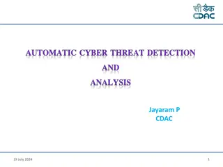
Intrusion Detection System (IDS)
•
Mechanism to monitor all network traffic to
determine evidence of compromise
•
Policy of what to detect?
–
How to specify policy?
–
What to detect?
•
Intrusion Prevention Systems
76
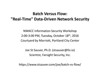
Network Security Research
•
Software Defined Networking
•
Firewalls
•
Intrusion Detection Systems
•
IPv6
•
IPSEC
•
…
77
The content delves into various aspects of network security, IP protocols, TCP/IP layering, IP addressing, CIDR, Internet Protocol (IP), and IP datagrams. It covers topics such as the Internet Protocol Suite, TCP/IP layering, IP addresses, Classless Inter-Domain Routing (CIDR), and the Internet Protocol (IP) protocol. The information provided sheds light on the fundamentals of network security and key protocols used for data transmission between network nodes.

Download Presentation

Please find below an Image/Link to download the presentation.
The content on the website is provided AS IS for your information and personal use only. It may not be sold, licensed, or shared on other websites without obtaining consent from the author.If you encounter any issues during the download, it is possible that the publisher has removed the file from their server.
You are allowed to download the files provided on this website for personal or commercial use, subject to the condition that they are used lawfully. All files are the property of their respective owners.
The content on the website is provided AS IS for your information and personal use only. It may not be sold, licensed, or shared on other websites without obtaining consent from the author.
E N D
Presentation Transcript
Network Security CSE 365 Information Assurance Spring 2020 Adam Doup Arizona State University http://adamdoupe.com
The Internet Protocol Suite Set of protocols used to transport data between nodes of a network Also known as the TCP/IP Protocol Suite Based on abstraction and encapsulation Link protocols Internet protocols Transport protocols Application protocols Adam Doup , Information Assurance
TCP/IP Layering SMTP HTTP DNS NFS Application Transport TCP UDP IGMP IP ICMP Internet ARP RARP Hardware Interface Link Physical Layer
IP Addresses Each host has one or more IP addresses for each network interface IPv4 addresses are composed of 32 bits Represented in dotted-decimal notation: 149.169.175.207 Adam Doup , Information Assurance
Classless Inter-Domain Routing (CIDR) Allocation of large chunks of IP addresses wasted an enormous number of IP addresses Number of hosts is increasing IPv6 provides a larger address space but adoption is slow CIDR is an addressing scheme from 1993 for the Internet which allows for more efficient allocation of IP addresses The netid/hostid boundary can be placed on any bit between 13 and 27 32 hosts minimum 524,288 hosts maximum Adam Doup , Information Assurance
Internet Protocol (IP) The IP protocol represents the glue of the Internet The IP protocol provides a connectionless, unreliable, best-effort datagram delivery service (delivery, integrity, ordering, non-duplication, and bandwidth is not guaranteed) IP datagrams can be exchanged between any two nodes (provided they both have an IP address) For direct communication IP relies on a number of different lower-level protocols, e.g., Ethernet, Token Ring, FDDI, RS-232, 802.11 Adam Doup , Information Assurance
IP Datagram RFC 791 0 4 8 12 16 20 24 28 31 Version HL Service type (TOS) Identifier Protocol Total length Flags Fragment offset Time To Live Header checksum Source IP address Destination IP address Options Padding Data Adam Doup , Information Assurance
IP Datagram RFC 791 0 4 8 12 16 20 24 28 31 Version HL Service type (TOS) Identifier Protocol Total length Flags Fragment offset Time To Live Header checksum Source IP address Destination IP address Options Padding Data Adam Doup , Information Assurance
IP Encapsulation IP header IP data Frame header Frame data
IP: Direct Delivery If two hosts are in the same physical network the IP datagram is encapsulated in a lower level protocol and delivered directly Subnetwork111.10.20 111.10.20.121 From 111.10.20.121 To111.10.20.14 111.10.20.14 From 09:45:FA:07:22:23 To0A:12:33:B2:C4:11 09:45:FA:07:22:23 0A:12:33:B2:C4:11 Adam Doup , Information Assurance
Ethernet Frame dest (6) src (6) type (2) data (46-1500) CRC (4) 0x0800 IP datagram 0x0806 ARP (28) PAD (18) 0x0808 RARP (28) PAD (18)
Ethernet Widely-used link-layer protocol Uses CSMA/CD (Carrier Sense, Multiple Access with Collision Detection) Destination address: 48 bits (e.g., 09:45:FA:07:22:23) Source address: 48 bits Type: 2 bytes (IP, ARP, RARP) Data: Min 46 bytes (padding may be needed) Max 1500 bytes CRC: Cyclic Redundancy Check, 4 bytes Adam Doup , Information Assurance
Address Resolution Protocol The address resolution protocol (ARP) allows a host to map IP addresses to the link-level addresses associated with the peer s hardware interface (e.g., Ethernet) to be used in direct delivery ARP messages are encapsulated in the underlying link level protocol Adam Doup , Information Assurance
ARP Request hosta# arp -a hosta# ping 192.168.1.10 8:0:46:7:4:a3 ff:ff:ff:ff:ff:ff arp 60: arp who-has 192.168.1.10 tell 192.168.1.100 0:1:3:1d:98:b8 8:0:46:7:4:a3 arp 60: arp reply 192.168.1.10 is-at 0:1:3:1d:98:b8 8:0:46:7:4:a3 0:1:3:1d:98:b8 ip 98: 192.168.1.100 > 192.168.1.10: icmp: echo request 0:1:3:1d:98:b8 8:0:46:7:4:a3 ip 98: 192.168.1.10 > 192.168.1.100: icmp: echo reply hosta# arp -a hostb (192.168.1.10) at 00:01:03:1D:98:B8 [ether] on eth0 hostb# arp -a hosta (192.168.1.100) at 08:00:46:07:04:A3 [ether] on eth0 ARP request ARP reply Host B 192.168.1.10 0:1:3:1d:98:b8 Host A 192.168.1.100 08:00:46:07:04:A3 Host C
Local Area Network Attacks Goals Impersonation of a host Denial of service Access to information Tampering with delivery mechanisms Sniffing Spoofing Hijacking Adam Doup , Information Assurance
Hubs vs. Switches Early network switches were simple hubs All traffic is broadcasted to all ports Modern network switches keep track of which interface is connected to each port All broadcast traffic is sent to all connected hosts All directed traffic is sent to the ports associated with the referenced hardware address Adam Doup , Information Assurance
Network Sniffing Technique at the basis of many attacks The attacker sets his/her network interface in promiscuous mode If switched Ethernet is used, then the switch must be convinced that a copy of the traffic needs to be sent to the port of the sniffing host Adam Doup , Information Assurance
Why Sniffing? Many protocols (FTP, POP, HTTP, IMAP) transfer authentication information in the clear By sniffing the traffic it is possible to collect usernames/passwords, files, mail, etc. Usually traffic is copied to a file for later analysis Adam Doup , Information Assurance
Sniffing Tools Tools to collect, analyze, and reply traffic Routinely used for traffic analysis and troubleshooting Command-line tools tcpdump: collects traffic tcpflow: reassemblesTCP flows tcpreplay: re-sends recorded traffic Graphical tools Wireshark Supports TCP reassembling Provides parsers for a number of protocols Adam Doup , Information Assurance
ARP Spoofing Goal: sniff all traffic between two hosts in a switched environment The attack leverages the stateless nature of the ARP protocol Replies without a request will be accepted The attacker host sends spoofed ARP messages to the two victim hosts, poisoning their cache The victim host sends their IP packets to the attacker host The attacker host acts has a router Adam Doup , Information Assurance
ARP Spoofing Host A Host B 192.168.1.100 at 08:00:46:07:04:A3 192.168.1.10 at 00:01:03:1d:98:b8 Host C 192.168.1.100 08:00:46:07:04:A3 192.168.1.10 00:01:03:1D:98:B8 192.168.1.137 at BA:DB:AD:BA:DB:AD 192.168.1.100 08:00:46:07:04:A3 192.168.1.10 00:01:03:1D:98:B8
ARP Spoofing ARP Reply: 192.168.1.10 is at BA:DB:AD:BA:DB:AD Host A Host B 192.168.1.100 at 08:00:46:07:04:A3 192.168.1.10 at 00:01:03:1d:98:b8 Host C 192.168.1.100 08:00:46:07:04:A3 192.168.1.10 00:01:03:1D:98:B8 192.168.1.137 at BA:DB:AD:BA:DB:AD 192.168.1.100 08:00:46:07:04:A3 192.168.1.10 00:01:03:1D:98:B8
ARP Spoofing ARP Reply: 192.168.1.10 is at BA:DB:AD:BA:DB:AD Host A Host B 192.168.1.100 at 08:00:46:07:04:A3 192.168.1.10 at 00:01:03:1d:98:b8 Host C 192.168.1.100 08:00:46:07:04:A3 192.168.1.10 BA:DB:AD:BA:DB:AD 192.168.1.137 at BA:DB:AD:BA:DB:AD 192.168.1.100 08:00:46:07:04:A3 192.168.1.10 00:01:03:1D:98:B8
ARP Spoofing ARP Reply: 192.168.1.100 is at BA:DB:AD:BA:DB:AD Host A Host B 192.168.1.100 at 08:00:46:07:04:A3 192.168.1.10 at 00:01:03:1d:98:b8 Host C 192.168.1.100 08:00:46:07:04:A3 192.168.1.10 BA:DB:AD:BA:DB:AD 192.168.1.137 at BA:DB:AD:BA:DB:AD 192.168.1.100 08:00:46:07:04:A3 192.168.1.10 00:01:03:1D:98:B8
ARP Spoofing ARP Reply: 192.168.1.100 is at BA:DB:AD:BA:DB:AD Host A Host B 192.168.1.100 at 08:00:46:07:04:A3 192.168.1.10 at 00:01:03:1d:98:b8 Host C 192.168.1.100 BA:DB:AD:BA:DB:AD 192.168.1.10 BA:DB:AD:BA:DB:AD 192.168.1.137 at BA:DB:AD:BA:DB:AD 192.168.1.100 08:00:46:07:04:A3 192.168.1.10 00:01:03:1D:98:B8
ARP Spoofing Ethernet: BA:DB:AD:BA:DB:AD IP: 192.168.1.100 Data: SECRET Host A Host B 192.168.1.100 at 08:00:46:07:04:A3 192.168.1.10 at 00:01:03:1d:98:b8 Host C 192.168.1.100 BA:DB:AD:BA:DB:AD 192.168.1.10 BA:DB:AD:BA:DB:AD 192.168.1.137 at BA:DB:AD:BA:DB:AD 192.168.1.100 08:00:46:07:04:A3 192.168.1.10 00:01:03:1D:98:B8
ARP Spoofing Ethernet: 00:01:03:1D:98:B8 IP: 192.168.1.10 Data: SECRET Host A Host B 192.168.1.100 at 08:00:46:07:04:A3 192.168.1.10 at 00:01:03:1d:98:b8 Host C 192.168.1.100 BA:DB:AD:BA:DB:AD 192.168.1.10 BA:DB:AD:BA:DB:AD 192.168.1.137 at BA:DB:AD:BA:DB:AD 192.168.1.100 08:00:46:07:04:A3 192.168.1.10 00:01:03:1D:98:B8
ARP Spoofing Legitimate ARP replies might restore the ARP cache to the correct value Most ARP-spoofing tool repeatedly send spoofed ARP replies to keep the ARP cache in the desired state ettercap Adam Doup , Information Assurance
IP Spoofing In an IP spoofing attack a host impersonates another host by sending a datagram with the address of the impersonated host as the source address Subnetwork111.10.20 111.10.20.121 From 111.10.20.76 To111.10.20.14 111.10.20.14 111.10.20.76 From 09:45:FA:07:22:23 To0A:12:33:B2:C4:11 09:45:FA:07:22:23 0A:12:33:B2:C4:11 Adam Doup , Information Assurance
Routing: Indirect Delivery If two hosts are in different physical networks the IP datagram is encapsulated in a lower level protocol and delivered to the directly connected gateway The gateway decides which is the next step in the delivery process This step is repeated until a gateway that is in the same physical subnetwork of the destination host is reached Then direct delivery is used Adam Doup , Information Assurance
Routing From 111.10.20.121 To 128.111.41.10 Source/Destination IP addresses are the same for every copy of the datagram TTL field is decreased at every step Link level addresses change at every step The delivery process is based on the destination address only A0:B0:C0:D0:E0:F0 A1:B1:C1:D1:E1:F1 111.10.20.121 AA:BB:CC:DD:EE:FF 128.111.41.10 11:21:31:41:51:61 From AA:BB:CC:DD:EE:FF To A0:B0:C0:D0:E0:F0 From A1:B1:C1:D1:E1:F1 To 11:21:31:41:51:61
Types of Routing Hop-by-hop routing The delivery route is determined by the gateways that participate in the delivery process Source routing The originator of a datagram determines the route to follow independently before sending the datagram (IP source routing option) Adam Doup , Information Assurance
Hop-by-hop Routing: The Routing Table The information about delivery is maintained in the routing table $ route n Kernel IP routing table Destination Gateway Genmask Flags Iface 192.168.1.24 0.0.0.0 255.255.255.255 UH eth0 192.168.1.0 0.0.0.0 255.255.255.0 U eth0 127.0.0.0 0.0.0.0 255.0.0.0 U lo 0.0.0.0 192.168.1.1 0.0.0.0 UG eth0 Flags U: the route is up G: the destination is a gateway H: the route is to a host (if not set, the route is to a network) D: the route was created by a redirectmessage M: the route was modified by a redirect message Adam Doup , Information Assurance
Routing Mechanism Search for a matching host address Search for a matching network address Search for a default entry If a match is not found a message of host unreachable or network unreachable is returned (by the kernel or by a remote gateway by using ICMP) Routing tables can be set Statically (at startup, or by using the "route" or "ip route" command) Dynamically (using routing protocols) Adam Doup , Information Assurance
TCP/IP Layering SMTP HTTP DNS NFS Application Transport TCP UDP IGMP IP ICMP Internet ARP RARP Hardware Interface Link Physical Layer
User Datagram Protocol (UDP) The UDP protocol relies on IP to provide a connectionless, unreliable, best-effort datagram delivery service (delivery, integrity, non-duplication, ordering, and bandwidth is not guaranteed) Introduces the port abstraction that allows one to address different message destinations for the same IP address Often used for multimedia (more efficient than TCP) and for services based on request/reply schema (DNS, NFS, RPC) Adam Doup , Information Assurance
UDP Message 0 4 8 12 16 20 24 28 31 UDP source port UDP message length UDP destination port Checksum Data Adam Doup , Information Assurance
UDP Message 0 4 8 12 16 20 24 28 31 UDP source port UDP message length UDP destination port Checksum Data Adam Doup , Information Assurance
UDP Encapsulation UDP header UDP data IP header IP data Frame header Frame data Adam Doup , Information Assurance
UDP Spoofing Basically IP spoofing Spoofed UDP request UDP reply Trusted client Server Attacker Adam Doup , Information Assurance
UDP Hijacking Variation of the UDP spoofing attack UDP request Spoofed UDP reply UDP reply UDP request Client Server Attacker Adam Doup , Information Assurance
UDP Portscan Used to determine which UDP services are available A zero-length UDP packet is sent to each port If an ICMP error message "port unreachable" is received the service is assumed to be unavailable Many TCP/IP stack implementations implement a limit on the error message rate, therefore this type of scan can be slow (e.g., Linux limit is 80 messages every 4 seconds) Adam Doup , Information Assurance
UDP Portscan % nmap -sU 192.168.1.10 Starting nmap by fyodor@insecure.org ( www.insecure.org/nmap/ ) Interesting ports on (192.168.1.10): (The 1445 ports scanned but not shown below are in state: closed) Port State Service 137/udp open netbios-ns 138/udp open netbios-dgm Nmap run completed -- 1 IP address (1 host up) scanned in 4 seconds Adam Doup , Information Assurance
Transmission Control Protocol (TCP) The TCP protocol relies on IP to provide a connection- oriented, reliable stream delivery service (no loss, no duplication, no transmission errors, correct ordering) TCP, as UDP, provides the port abstraction TCP allows two nodes to establish a virtual circuit, identified by source IP address, destination IP address, source TCP port, destination TCP port The virtual circuit is composed of two streams (full- duplex connection) The couple IP address/port number is sometimes called a socket (and the two streams are called a socket pair) Adam Doup , Information Assurance
TCP Segment 0 4 8 12 16 20 24 28 31 Source port Destination port Sequence number Acknowledgment number Flags HLEN Reserved Window Urgent pointer Checksum Options Padding Data Adam Doup , Information Assurance
TCP Segment 0 4 8 12 16 20 24 28 31 Source port Destination port Sequence number Acknowledgment number Flags HLEN Reserved Window Urgent pointer Checksum Options Padding Data Adam Doup , Information Assurance
TCP Encapsulation TCP header TCP data IP header IP data Frame header Frame data
TCP Seq/Ack Numbers The sequence number specifies the position of the segment data in the communication stream (SYN=13423 means: the payload of this segment contains the data from byte 13423 to byte 13458) The acknowledgment number specifies the position of the next byte expected from the communication partner (ACK = 16754 means: I have received correctly up to byte 16753 in the stream, I expect the next byte to be 16754) These numbers are used to manage retransmission of lost segments, duplication, flow control Adam Doup , Information Assurance
TCP Flags Flags are used to manage the establishment and shutdown of a virtual circuit SYN: request for the synchronization of syn/ack numbers (used in connection setup) ACK: states the acknowledgment number is valid (all segment in a virtual circuit have this flag set, except for the first one) FIN: request to shutdown one stream RST: request to immediately reset the virtual circuit URG: states that the Urgent Pointer is valid PSH: request a push operation on the stream (that is, the stream data should be passed to the user application as soon as possible) Adam Doup , Information Assurance
TCP Virtual Circuit: Setup A server, listening to a specific port, receives a connection request from a client: The segment containing the request is marked with the SYN flag and contains a random initial sequence number Sc The server answers with a segment marked with both the SYN and ACK flags and containing an initial random sequence number Ss Sc + 1 as the acknowledgment number The client sends a segment with the ACK flag set and with sequence number Sc + 1 and acknowledgment number Ss + 1 Adam Doup , Information Assurance


")


")