Neidhart System and Screen Mount Types
The history of the Neidhart System for screen mounts, developed at the University of Pretoria for the mining industry. Explore the advantages of various screen mount types like Standard AR/CR, Compact AD/CD, Stainless Steel S4, and Suspended AS/HS in vibratory equipment applications.

Download Presentation

Please find below an Image/Link to download the presentation.
The content on the website is provided AS IS for your information and personal use only. It may not be sold, licensed, or shared on other websites without obtaining consent from the author.If you encounter any issues during the download, it is possible that the publisher has removed the file from their server.
You are allowed to download the files provided on this website for personal or commercial use, subject to the condition that they are used lawfully. All files are the property of their respective owners.
The content on the website is provided AS IS for your information and personal use only. It may not be sold, licensed, or shared on other websites without obtaining consent from the author.
E N D
Presentation Transcript
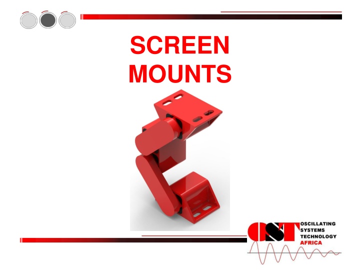
SCREEN MOUNTS
INDEX History Neidhart System Screen Mount Types Advantages Selecting Screen Mounts Screen Mount Calculations Fault Finding Installation
History The Laboratory of Advanced Engineering at the University of Pretoria was given the task to develop a cost effective screen mount for the mining industry. The concept or system that met most of the requirements was the Neidhart Concept. In April 1992 a series of Neidhart Screen Mounts was developed and tested on screens in the laboratory and in the production environment.
Neidhart system The Neidhart System consist of an outer tube, 4 special round rubber and an inner tuber Torsional force is achieved when the inner tube is turned within the outer tube acting out a force on the rubber
Screen Mount Types Standard AR/CR The OST Screen Mounts Type AR/CR are specifically designed to support vibratory equipment or drive systems. These mounts remove harmful resident frequencies that cause spring damage due to an inefficient system that utilizes coil spring suspensions and eliminates resulting safety concerns. They have standard rubbermix 10 inserts and can be used for applications operating within a -40 to 80 temperature.
Screen Mount Types continue Compact AD/CD The OST Screen Mounts type AD/CD are a compact design with a much higher load capacity than the standard Mounts, ideal for two mass systems. They have standard rubbermix 10 rubber inserts and can be used for applications operating within a -40 to 80 C temperature range.
Screen Mount Types continue Stainless Steel S4 The OST Screen Mount stainless steel design specific for the food, pharmaceutical and wash down requirements. All housings, arms and inner have standard 10 rubber inserts and can be used for applications operating within a - 40 to 80 C temperature range.
Screen Mount Types continue Suspended AS/HS The OST Screen Mounts Type AS/HS are specifically designed to suspend vibratory equipment or drive systems. These mounts remove harmful resident frequencies that cause spring damage due to an inefficient system that utilizes coil spring suspensions and eliminates resulting safety concerns. They have standard rubbermix 10 inserts and can be used for applications operating within a -40 to 80 temperature.
Screen mount types continue Heavy Duty AH/HR The OST Screen Mounts Type AH/HR are specifically designed for heavy duty impact loads on vibratory equipment or drive systems. They have standard rubbermix 10 inserts and can be used for applications operating within a -40 to 80 temperature.
Advantages Effective screen control Elimination of side ways movement Reduced amplitudes during deceleration Vibration isolation Excellent acoustic isolation No operation cost during lifetime No down-time or lost production due to suspension failure No maintenance required No breakage due to mechanical failure Generally much safer to install and remove than conventional springs Adapter plates can be supplied for retrofit applications Resistant to dust, water, corrosion Decreased possible damage to equipment Item Damage during startup Damage during stoppage Running Damage done for start-up & stoppage Screen Mount CoilSpring 8.77% 10.05% ~0 18.80% 3.00% 22.57% ~0 25.60%
Selecting Screen Mounts Information required 1. 2. 3. Total mass of screen (kg) Material on trough (kg) Load per point or mass distribution P2 P1 P2 P1 P2 P1 OST WILL DO CALCULATION
Screen Mount Calculations Additional calculations Dynamic loads (F) in Newton n = kd = s = m = Insulation efficiency (W) no of screen mounts spring rate dynamic stroke peak to peak load of screen fe Fe fn = = = excitation frequency rpm of motor/60 natural frequency of screen mount (from technical sheets) Spring rate static (ks) M fn = = load of screen natural frequency of screen mount
Layout with Adaptor Plates Feed end Discharge end Bottom and top must be vertically in line Top adaptor plates Direction of installation: Same as flow of material Bottom adaptor plates
Fault Finding .Top and bottom mounting plates are not parallel to side plates .Different torque values will occur in units .Unit will try to equalize back to neutral axis .Result will force rubber out of position .Less mass can be accommodated by unit .Unit will have lower deflection .Units will reach saturation very quickly .Top and bottom squares do not align vertically .Units are pre-tensioned .Different loaded heights .Life expectancy of SM units decreases
Fault Finding continue .Top plate is not level .Rubber is being forced as per drawing .Different torque values are experienced in each square section, resulting in different stiffness throughout the unit .Rubber will be forced to work itself out to compensate for neutral position .Result is different loaded heights . .Units are pre-tensioned .Different torque values occur within the unit .Different loaded heights are experienced by unit .Detrimental to screen .Lifetime of screen mounts jeopardized . Resonance The larger cyclic forces transmitted by the RunRight system will cause an increase in excitation of the supporting structure if the natural frequency is at the excitation frequency of the screen or at one of the harmonics, the supporting structure will be excited due to resonance. In this case the supporting structure must be stiffened in order to increase the natural frequency to more than the excitation frequency of the screen.If a resonance problem exist for one suspension type, it will also exist for the other suspension, although it will be more severe for a RunRight suspension due to the higher transmitted forces The failure mechanism of a RunRight suspension allows for predictive maintenance, while failure of coil spring suspension might be difficult to predict.