Laser Alignment Issues: Troubleshooting and Solutions
Discover the journey of resolving alignment problems in laser systems post-movement. From power fluctuations to damaged connectors, follow the troubleshooting steps taken to realign and optimize laser power output effectively.

Download Presentation

Please find below an Image/Link to download the presentation.
The content on the website is provided AS IS for your information and personal use only. It may not be sold, licensed, or shared on other websites without obtaining consent from the author. If you encounter any issues during the download, it is possible that the publisher has removed the file from their server.
You are allowed to download the files provided on this website for personal or commercial use, subject to the condition that they are used lawfully. All files are the property of their respective owners.
The content on the website is provided AS IS for your information and personal use only. It may not be sold, licensed, or shared on other websites without obtaining consent from the author.
E N D
Presentation Transcript
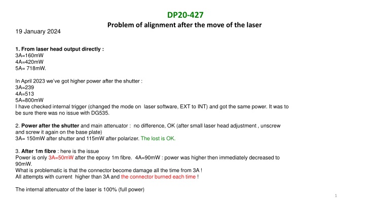
DP20-427 Problem of alignment after the move of the laser 19 January 2024 1. From laser head output directly : 3A=160mW 4A=420mW 5A= 718mW. In April 2023 we ve got higher power after the shutter : 3A=239 4A=513 5A=800mW I have checked internal trigger (changed the mode on laser software, EXT to INT) and got the same power. It was to be sure there was no issue with DG535. 2. Power after the shutter and main attenuator : no difference, OK (after small laser head adjustment , unscrew and screw it again on the base plate) 3A= 150mW after shutter and 115mW after polarizer. The lost is OK. 3. After 1m fibre : here is the issue Power is only 3A=50mW after the epoxy 1m fibre. 4A=90mW : power was higher then immediately decreased to 90mW. What is problematic is that the connector become damage all the time from 3A ! All attempts with current higher than 3A and the connector burned each time ! The internal attenuator of the laser is 100% (full power) 1
DP20-427 Problem of alignment after the move of the laser 22 January 2024 With 3A: Sortie laser: 160mW After shutter: 150mW Before fibre: 115mW After coupling: it should be 80% of the power so around 90mW and we have only 50mW. Problem was the focusing: need to move the 3-stage axis on left side , to optimize the power. Check few times the fibre end to see if no burning around 3A. 23 January 2024 Pump current (A) 2.5 3 3.5 4 4.5 5 P 2023 after shutter 108 239 P 2024 laser output P after 1m coupling 35 97 167 250 340 P after shutter P after polarizer 50 145 255 380 514 646 162 278 410 550 690 115 200 300 404 75% of the power after the polarizer 513 800 480 423 Problem again of burning but at 6A. Before it was 3A Increase 580 then 500 6 1090 969 919 697 800 904 6.5 7 1110 1240 1050 1200 1380 2
DP20-427 Problem of alignment after the move of the laser 24 January 2024 Thorlabs beam profiler : need trigger from DG535. Measure the distance from support plate to the CCD camera of beam profiler and same with the 3-stage axis to the fibre. - use 5% shot102 attenuation, 10-13% internal DP attenuation . Power currant at 2.3A 1) Get 2 peaks for X axis ! Moving the beam profiler from few cm towards the focus lens didn t help. On Y axis it seems OK, around 300um. 2) There is well 2 visible beam spots from the direct DP2 output. => move the shutter to block one beam spot => Better on beam profiler, only one peak => check the power : power lower ! 3A = 87 (was 97) 3.5A=135 (was 167) 4A=200 (was 250) Still not OK and power too low 3
DP20-427 Problem of alignment after the move of the laser 25-30 January 2024 1) Use the beam profiler on the DP20 output directly. Around 10% internal attenuator. Result: same, 2 peaks. 2) Check laser configuration: Gate source should be INT according to last good setting from Photonics. => no difference on the pulse. 3) Suggested tests by Photonics: - check laser setting INT EXT gate control : OK. - change the temperature of the crystal (SHG): no improvement - change the internal attenuator to see if it is not damaged: OK - moving 2 motors axis to test if the problem is from mechanical shift or from damage: issue solved ! Get only one peak on X From Photonics it is due to the move of the laser : stress on the base is responsible of this offset. (thin Teflon spacer could be inserted) 4) Re-aligned main coupling of the 3 axis stage: one more burned fibre. No more high epoxy fibre. 5) Redo 2 fibres with high epoxy ! Could run the laser with standard fibre because only low power is needed. 4