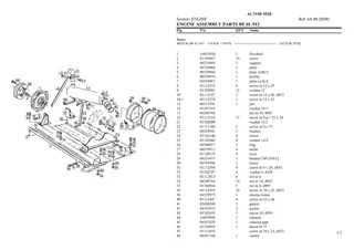
John Deere 5220 5320 5420 5520 Tractor Operator Manual Instant Download
Please open the website below to get the complete manualnn//
Download Presentation

Please find below an Image/Link to download the presentation.
The content on the website is provided AS IS for your information and personal use only. It may not be sold, licensed, or shared on other websites without obtaining consent from the author. Download presentation by click this link. If you encounter any issues during the download, it is possible that the publisher has removed the file from their server.
E N D
Presentation Transcript
5220, 5320, 5420, and 5520 Tractor Operation and Test TECHNICAL MANUAL 5220, 5320, 5420, and 5520 Tractor Operation and Test TM2049 18MAR02 (ENGLISH) For complete service information also see: 5220, 5320, 5420, and 5520 Tractor Repair. . . . . . . . . . . . . . . . . . . . . . . . . . . . . . . Component Technical Manual 4045 Engine . . . . . . . . . . . . . . . . . . . . . . . . . . . . . . Component Technical Manual 4045 Mechanical Fuel System . . . . . . . . . . . . . . . . Component Technical Manual 3029 Engine . . . . . . . . . . . . . . . . . . . . . . . . . . . . . . Alternators and Starting Motors. . . . . . . . . . TM2048 CTM104 CTM207 CTM125 CTM77 John Deere Augusta Works LITHO IN U.S.A.
Introduction Foreword This manual is written for an experienced technician. Essential tools required in performing certain service work are identified in this manual and are recommended for use. Information is organized in groups for the various components requiring service instruction. At the beginning of each group are summary listings of all applicable essential tools, service equipment and tools, other materials needed to do the job, service parts kits, specifications, wear tolerances, and torque values. Live with safety: Read the safety messages in the introduction of this manual and the cautions presented throughout the text of the manual. Technical Manuals are concise guides for specific machines. They are on-the-job guides containing only the vital information needed for diagnosis, analysis, testing, and repair. This is the safety-alert symbol. When you see this symbol on the machine or in this manual, be alert to the potential for personal injury. Fundamental service information is available from other sources covering basic theory of operation, fundamentals of troubleshooting, general maintenance, and basic type of failures and their causes. Technical manuals are divided in two parts: repair and operation and tests. Repair sections tell how to repair the components. Operation and tests sections help you identify the majority of routine failures quickly. DX,TMIFC 19 29SEP98 1/1 TM2049 (18MAR02) 5220, 5320, 5420, and 5520 Tractors 031802 PN=2
Contents 210 SECTION 210 Operational Checkout Procedures Group 10 Operational Checkout Procedures and Adjustments Group 05 Component Location Group 10 Theory of Operation Group 15 Diagnosis Group 16 Hydraulic Tests Without SCV Group 17 Hydraulic Tests With SCV Group 18 Hydraulic Tests All Group 19 Adjustments Group 20 Hydraulic Schematics SECTION 220 Engine Operation, Tests, and Adjustments Group 05 Component Location Group 10 Theory of Operation Group 15 Diagnosis, Tests, and Adjustments 220 SECTION 230 Fuel/Air Operation, Tests, and Adjustments Group 05 Component Location Group 10 Theory of Operation Group 15 Diagnosis, Tests and Adjustments SECTION 290 Operator Station Group 05 Component Location Group 10 Theory of Operation Group 15 Diagnosis, Tests, and Adjustments 230 SECTION 299 Dealer Fabricated Tools Group 00 Dealer Fabricated Tools 240 SECTION 240 Electrical System Operation, Test & Adjust Group 05 Component Location Group 10 Theory of Operation Group 15 Diagnosis, Test and Adjust Group 20 Wiring Schematics 250 SECTION 250 Power Train Operation, Tests andAdjustments Group 05 Component Location CollarShift/SyncShuttle Transmission Group 06 Component Location PowrReverser Transmission Group 10 Theory of Operation CollarShift/SyncShuttle Transmission Group 11 Theory of Operation PowrReverser Transmission Group 15 Diagnosis, Tests, and Adjustments CS/SS Transmission Group 16 Diagnosis, Tests, and Adjustments PowrReverser 260 270 290 SECTION 260 Steering and Brake Operation, Test & Adjust Group 05 Component Location Group 10 Theory of Operation Group 15 Diagnosis, Tests and Adjustments 299 SECTION 270 Hydraulic System Operation,Tests, All information, illustrations and specifications in this manual are based on the latest information available at the time of publication. The right is reserved to make changes at any time without notice. INDX COPYRIGHT 2002 DEERE & COMPANY Moline, Illinois All rights reserved A John Deere ILLUSTRUCTION Manual i TM2049 (18MAR02) 5220, 5320, 5420, and 5520 Tractors 031802 PN=1
https://www.ebooklibonline.com Hello dear friend! Thank you very much for reading. Enter the link into your browser. The full manual is available for immediate download. https://www.ebooklibonline.com
Contents 210 220 230 240 250 260 270 290 299 INDX ii TM2049 (18MAR02) 5220, 5320, 5420, and 5520 Tractors 031802 PN=2
210 Section 210 Operational Checkout Procedures Contents Page Page Group 10 Operational Checkout Procedures Specifications . . . . . . . . . . . . . . . . . . . . . . . . .210-10-1 Operational Checkout Procedure Information. . . . . . . . . . . . . . . . . . . . . . . . . .210-10-1 Engine Oil Level and Condition Check . . . . . .210-10-2 Coolant Level and Condition Check . . . . . . . .210-10-3 Transmission and Hydraulic Oil Check . . . . . .210-10-4 3-Cylinder Fan and V-Belt Check . . . . . . . . . .210-10-5 4-Cylinder Fan and Serpentine Belt Check . . .210-10-6 Compressor Belt Check . . . . . . . . . . . . . . . . .210-10-7 Fuel System Check. . . . . . . . . . . . . . . . . . . . .210-10-8 Air Intake System Check. . . . . . . . . . . . . . . . .210-10-9 Electrical System Check . . . . . . . . . . . . . . . .210-10-10 Hydraulic System Check . . . . . . . . . . . . . . . .210-10-11 MFWD Oil Check . . . . . . . . . . . . . . . . . . . . .210-10-12 MFWD Differential Oil Check. . . . . . . . . . . . .210-10-12 Indicator Lamps Check . . . . . . . . . . . . . . . . .210-10-13 Cab Blower Motor Check . . . . . . . . . . . . . . .210-10-14 A/C Compressor Clutch Check . . . . . . . . . . .210-10-15 Engine Start Check Straddle Mount Tractors . . . . . . . . . . . . . . . . . . . . . . . . . . .210-10-16 Engine Start Check Isolated Open Operator Station and Cab Tractors . . . . . .210-10-17 Transmission Neutral Start Check Straddle Mount Tractors . . . . . . . . . . . . . . . . . . . . .210-10-18 Transmission Neutral Start Check Isolated Open Operator Station and Cab Tractors . . . . . . . . . . . . . . . . . . . . . . . . . . .210-10-19 PTO Neutral Start Check. . . . . . . . . . . . . . . .210-10-20 Engine Fast and Slow Idle Operation . . . . . .210-10-21 Foot Throttle Pedal Check Isolated Open Operator Station and Cab Tractors . . . . . .210-10-22 Power Steering Check. . . . . . . . . . . . . . . . . .210-10-23 Differential Lock Check . . . . . . . . . . . . . . . . .210-10-23 PTO Engagement Check. . . . . . . . . . . . . . . .210-10-24 Clutch Check. . . . . . . . . . . . . . . . . . . . . . . . .210-10-25 Transmission Shift Check . . . . . . . . . . . . . . .210-10-26 Range Lever Shift Check . . . . . . . . . . . . . . .210-10-27 MFWD Drive Check . . . . . . . . . . . . . . . . . . .210-10-28 Brake Check . . . . . . . . . . . . . . . . . . . . . . . . .210-10-29 Park Brake Check CollarShift and SYNCSHUTTLE Transmissions . . . . . . .210-10-30 Park Brake Check POWRREVERSER Transmission . . . . . . . . . . . . . . . . . . . . . . .210-10-31 Rockshaft Check Straddle Mount Tractors . . . . . . . . . . . . . . . . . . . . . . . . . . .210-10-32 Rockshaft Check Isolated Open Operator Station and Cab Tractors . . . . . .210-10-33 Selective Control Valve Check Straddle Mount Tractors . . . . . . . . . . . . . . . . . . . . .210-10-34 Selective Control Valve Check Isolated Open Operator Station and Cab Tractors . . . . . . . . . . . . . . . . . . . . . . . . . . .210-10-35 Front End Loader Joystick Control Check (Optional). . . . . . . . . . . . . . . . . . . . . . . . . .210-10-36 A/C System Operational Check. . . . . . . . . . .210-10-37 Cab Heater Valve Check. . . . . . . . . . . . . . . .210-10-38 Miscellaneous Checks. . . . . . . . . . . . . . . . . .210-10-38 210-1 TM2049 (18MAR02) 5220, 5320, 5420, and 5520 Tractors 031802 PN=1
Contents 210 210-2 TM2049 (18MAR02) 5220, 5320, 5420, and 5520 Tractors 031802 PN=2
Group 10 Operational Checkout Procedures 210 10 1 Specifications Item Measurement Specification 825 25 Engine Slow Idle Speed Rotation 2625 25 Engine Fast Idle Speed Rotation OUO1082,0000190 19 26MAR01 1/1 Operational Checkout Procedure Information The procedures covered in this group are used to give a quick checkout of all the systems and components on the unit. These checkouts should be run to ensure proper operation after any extended storage, when the unit comes in for service, and after repairs have been made on the unit. They can also be helpful in determining the value of the unit at trade-in time. The unit should be placed on a level surface to run the checkouts. All the checkouts should be done and all of the steps of each checkout should be followed. Each checkout lists: Conditions How the unit should be set up for the checkout. Procedure The specific action to be done. Normal What should happen or be heard or be seen. If Not Normal Where to go if other tests or adjustments are needed. When performing the checkout, be sure to set your machine up to the test conditions listed and follow the sequence carefully. The Normal paragraph gives the result that should happen when performing the checkout. If the results are not normal, go to the Section and Group listed in the If Not Normal paragraph to determine the cause and repair the malfunction. The photograph that accompanies each checkout procedure is included to help conduct the checkout. MX,21010HE,1A 19 12SEP00 1/1 210-10-1 TM2049 (18MAR02) 5220, 5320, 5420, and 5520 Tractors 031802 PN=7
Operational Checkout Procedures 210 10 Engine Oil Level and Condition Check 2 CONDITIONS: Machine parked on flat, level surface. Key switch in OFF position. Transmission in park position. Engine not run for at least five minutes. UN 06AUG90 PROCEDURE: M45603 Clean dirt from area around dipstick opening. Remove and wipe off dipstick. Install dipstick until seated in tube. Remove dipstick and check level and condition of oil. NORMAL: Oil level between full and add marks of dipstick. Oil not excessively thick or thin. No fuel odor in oil. No visible foreign material in oil. IF NOT NORMAL: Add proper oil to full mark on dipstick. (See Transmission and Hydraulic Oil in TM2048 Section 10, Group 20.) Replace contaminated oil and filter. See Section 220, Group 15 for Diagnosis, Tests, and Adjustments OUO1082,0000140 19 13MAR01 1/1 210-10-2 TM2049 (18MAR02) 5220, 5320, 5420, and 5520 Tractors 031802 PN=8
Operational Checkout Procedures 210 10 3 Coolant Level and Condition Check CONDITIONS: Machine parked on flat, level surface. Key switch in OFF position. Transmission in park position. PROCEDURE: Observe level of coolant in recovery tank. Check condition of recovery tank and tank-to-radiator hose. NORMAL: UN 09JUN00 Recovery tank and hose in good condition, no holes or cracks. Coolant at full mark if engine at operating temperature. Coolant clean; no oil, rust-like discoloration or foreign material in fluid. LV4946 3-Cylinder Engine IF NOT NORMAL: Replace recovery tank or hose, add coolant, and recheck level after operation. Add coolant to proper mark on tank. Check radiator-to-tank hose and recovery tank for holes or cracks. Change coolant and flush cooling system. See Section 220, Group 15 for Diagnosis, Tests, and Adjustments. UN 09JUN00 LV4947 4-Cylinder Engine OUO1082,0000141 19 13MAR01 1/1 210-10-3 TM2049 (18MAR02) 5220, 5320, 5420, and 5520 Tractors 031802 PN=9
Operational Checkout Procedures 210 10 Transmission and Hydraulic Oil Check 4 CONDITIONS: Machine parked on flat, level surface. Key switch in OFF position. Transmission in park position. UN 15FEB01 PROCEDURE: LV6183 Straddle mount tractors: Clean dirt from area around dipstick opening (A). Isolated open operator platform and cab tractors: Clean dirt from area around dipstick opening (B). Remove and wipe off dipstick. Install dipstick until seated in tube. Remove dipstick and check level and condition of oil. NORMAL: UN 14MAR01 Oil level between full and add marks of dipstick. Oil not excessively thick or thin. No visible foreign material in oil. LV6475 IF NOT NORMAL: A Dipstick (Straddle Mount Tractor) B Dipstick (Isolated Open Operator Station or Cab Tractors) Add proper oil to full mark on dipstick. Replace contaminated oil and filter. See Diagnosis, Tests, and Adjustments CS/SS Transmission (Section 250, Group 15), Diagnosis, Tests and Adjustments (Section 260, Group 15), or Diagnosis (Section 270, Group 15) for transmission and hydraulic system diagnosis, tests and adjustments. OUO1082,0000126 19 08MAR02 1/1 210-10-4 TM2049 (18MAR02) 5220, 5320, 5420, and 5520 Tractors 031802 PN=10
Operational Checkout Procedures 210 10 5 3-Cylinder Fan and V-Belt Check CONDITIONS: Key switch in OFF position. Engine not run for at least 15 minutes. Transmission in park position. UN 15FEB01 PROCEDURE: LV6192 Inspect fan and V-belt for damage. Check belt tension. (See Fan/Alternator V-Belt Adjustment 5220 and 5320 Tractors in Section 220, Group 15.) NORMAL: Fan undamaged; no cracks or bent blades. Belt not cracked, frayed or glazed. Belt does not squeal during operation. IF NOT NORMAL: Replace damaged fan or belt. Adjust belt tension. (See Fan/Alternator V-Belt Adjustment 5220 and 5320 Tractors in Section 220, Group 15.) OUO1082,0000142 19 13MAR01 1/1 210-10-5 TM2049 (18MAR02) 5220, 5320, 5420, and 5520 Tractors 031802 PN=11
Operational Checkout Procedures 210 10 4-Cylinder Fan and Serpentine Belt Check 6 CONDITIONS: Key switch in OFF position. Engine not run for at least 15 minutes. Transmission in park position. PROCEDURE: Inspect fan and serpentine belt for damage. Check belt tensioner (A) spring tension. (See Inspect and Replace Belt Tensioner Models 5420 and 5520 in TM2048 Section 20, Group 10.) UN 15FEB01 NORMAL: LV6178 Fan undamaged; no cracks or bent blades. Belt not cracked, frayed or glazed. Belt does not squeal during operation. A Belt Tensioner IF NOT NORMAL: Replace damaged fan or serpentine belt. Replace belt tensioner. (See Inspect and Replace Belt Tensioner Models 5420 and 5520 in TM2048 Section 20, Group 10.) OUO1082,0000146 19 28FEB02 1/1 210-10-6 TM2049 (18MAR02) 5220, 5320, 5420, and 5520 Tractors 031802 PN=12
Operational Checkout Procedures 210 10 7 Compressor Belt Check NOTE: Three-cylinder engine shown. Some procedures for the four-cylinder engine are slightly different. See specifics below. NOTE: Air intake tube removed for clarity of photo. CONDITIONS: Key switch in OFF position. Engine not run for at least 15 minutes. Transmission in park position. PROCEDURE: UN 15FEB01 Inspect belt for damage. 3-cylinder engines: Check belt tension. (See Fan/Alternator V-Belt Adjustment 5220 and 5320 Tractors and Compressor Drive Belt Adjustment 3-Cylinder in Section 220, Group 15.) 4-cylinder engines: Inspect belt tensioner and spring tension. (See Inspect and Replace Belt Tensioner Models 5420 and 5520 in TM2048 Section 20, Group 10.) LV6184 NORMAL: Belt not cracked, frayed or glazed. Belt does not squeal during operation. IF NOT NORMAL: Replace damaged compressor belt. 3-cylinder engines: Adjust belt tension. (See Fan/Alternator V-Belt Adjustment 5220 and 5320 Tractors and Compressor Drive Belt Adjustment 3-Cylinder in Section 220, Group 15.) 4-cylinder engines: Replace belt tensioner. (See Inspect and Replace Belt Tensioner Models 5420 and 5520 in TM2048 Section 20, Group 10.) OUO1082,0000147 19 28FEB02 1/1 210-10-7 TM2049 (18MAR02) 5220, 5320, 5420, and 5520 Tractors 031802 PN=13
Operational Checkout Procedures 210 10 Fuel System Check 8 CONDITIONS: Machine parked on flat, level surface. Key switch in OFF position. Transmission in park position. Straddle mount tractors: Fuel drain valve (A) closed. Isolated open operator station or cab tractors: Fuel drain valve (B) closed. Fuel shut-off valve (C) open. UN 15FEB01 LV6187 PROCEDURE: Observe fuel level and condition. Check fuel tank cap and seal condition. Check fuel filter (D) condition. Check fuel tank, lines, and hoses for kinks, leaks, or damage. UN 15FEB01 NORMAL: LV6185 Fuel level OK. Correct type and grade of clean fuel. Fuel tank overflow hose and vent valve in good condition. (No pressure or vacuum observed in fuel tank when cap is removed.) No leaks in system. No water or sediment in fuel filter bowl. IF NOT NORMAL: Add correct type and grade of clean fuel. (See Section 10, Group 20 in TM2048.) Clean contaminated fuel tank, filter, or lines. Repair or replace damaged fuel tank, cap, drain valve, filter, or lines. (See Section 30, Group 05 in TM2048.) UN 15FEB01 LV6186 A Fuel Drain Valve (Straddle Mount) B Fuel Drain Valve (Isolated Open Operator Station or Cab Tractors) C Fuel Shut-Off Valve D Fuel Filter OUO1082,0000125 19 08MAR02 1/1 210-10-8 TM2049 (18MAR02) 5220, 5320, 5420, and 5520 Tractors 031802 PN=14
Suggest: If the above button click is invalid. Please download this document first, and then click the above link to download the complete manual. Thank you so much for reading
Operational Checkout Procedures 210 10 9 Air Intake System Check CONDITIONS: Key switch in OFF position. Transmission in park position. PROCEDURE: Observe condition of primary and secondary air filter elements. Check condition of air intake hose, tube, and turbocharger (if equipped). Observe air cleaner restriction indicator on dash (engine running). UN 15FEB01 LV6189 NORMAL: Air Filter (5320 Shown) Air intake and elements free of debris. Air intake hoses and tube in good condition. Hose clamps tight. Intake tube gasket intact. Air cleaner unloader valve not plugged. Air cleaner housing sealed. Air cleaner restriction indicator light off. Turbocharger (if equipped) operates with no grinding or bearing noise. IF NOT NORMAL: Clean, repair or replace as required. 5320 and 5520 tractors: Repair damaged turbocharger, (if equipped). See Section 220, Group 15 for diagnosis, tests, and adjustments. See Section 30, Group 10 for inspection and repair. UN 15FEB01 LV6196 Turbocharger (5320 Shown) OUO1082,0000143 19 28FEB02 1/1 210-10-9 TM2049 (18MAR02) 5220, 5320, 5420, and 5520 Tractors 031802 PN=15
https://www.ebooklibonline.com Hello dear friend! Thank you very much for reading. Enter the link into your browser. The full manual is available for immediate download. https://www.ebooklibonline.com

