John Deere 17D Compact Excavator Service Repair Manual Instant Download (TM10259)
Please open the website below to get the complete manualnn// n
Download Presentation

Please find below an Image/Link to download the presentation.
The content on the website is provided AS IS for your information and personal use only. It may not be sold, licensed, or shared on other websites without obtaining consent from the author. Download presentation by click this link. If you encounter any issues during the download, it is possible that the publisher has removed the file from their server.
E N D
Presentation Transcript
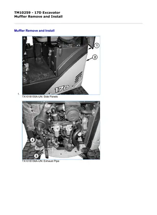
1/3 TM10259 - 17D Excavator Muffler Remove and Install Muffler Remove and Install 1. TX1018155A-UN: Side Panels TX1018156A-UN: Exhaust Pipe file:///C:/ProgramData/Service%20ADVISOR/Temp/TM10259_09001faa805... 2019/11/15
2/3 T207372A-UN: Muffler LEGEND: 1 - Side Panel 2 - Side Panel 3 - Exhaust Pipe Clamp 4 - Exhaust Pipe-to-Muffler Clamp 5 - Muffler-to-Exhaust Manifold Nut (4 used) 6 - Muffler Bracket Cap Screw Park machine on level surface. 2. Remove side panels (1 and 2). 3. Remove counterweight. See Counterweight Remove and Install . (Group 1749.) 4. NOTE: If exhaust pipe needs to be replaced, remove exhaust pipe-to-muffler clamp (4). Remove exhaust pipe clamp (3). 5. Remove four muffler-to-exhaust manifold nuts (5) and washers. 6. Remove muffler bracket cap screw (6) and remove muffler. 7. Install muffler gasket and muffler. 8. Install muffler bracket cap screw (6). 9. Install muffler-to-exhaust manifold nuts (5) and tighten. 10. NOTE: If removed, tighten exhaust pipe-to-muffler clamp (4). Install exhaust pipe clamp (3). 11. Install counterweight and left-side panels. See Counterweight Remove and Install . (Group 1749.) file:///C:/ProgramData/Service%20ADVISOR/Temp/TM10259_09001faa805... 2019/11/15
1/2 TM10259 - 17D Excavator Thermostat Remove and Install Thermostat Remove and Install M82315A-UN: Thermostat LEGEND: A - Thermostat Cover Cap Screw (2 used) B - Thermostat Cover C - Cover Gasket D - Thermostat E - Gasket 1. Remove counterweight. See Counterweight Remove and Install . (Group 1749.) 2. Drain cooling system into an appropriate container for storage or disposal. See Draining Cooling System . (Operator's Manual.) 3. Remove air cleaner assembly. See Air Cleaner Assembly Remove and Install . (Group 0400.) 4. Remove thermostat cover cap screws (A). 5. Remove thermostat cover (B), cover gasket (C), thermostat (D), and gasket (E). 6. Test thermostat. See Engine Thermostat Test . (Group 9010-25.) 7. At installation, replace gaskets. 8. Install thermostat, gaskets, thermostat cover, and thermostat cover cap screws and tighten to specification. Item Measurement Specification Thermostat Cover Cap Screw Torque 20 N m 15 lb-ft file:///C:/ProgramData/Service%20ADVISOR/Temp/TM10259_09001faa805... 2019/11/15
https://www.ebooklibonline.com Hello dear friend! Thank you very much for reading. Enter the link into your browser. The full manual is available for immediate download. https://www.ebooklibonline.com
2/2 9. Fill cooling system. See Cooling System Fill and Deaeration . (Operator's Manual.) 10. Install counterweight. See Counterweight Remove and Install . (Group 1749.) MH66O88,0000508-19-20070522 file:///C:/ProgramData/Service%20ADVISOR/Temp/TM10259_09001faa805... 2019/11/15
1/2 TM10259 - 17D Excavator Water Pump Remove and Install Water Pump Remove and Install RG8583A-UN: Water Pump LEGEND: A - Water Pump B - Fan-to-Water Pump Cap Screw (4 used) C - Fan D - Spacer E - Pulley F - Fan Belt G - Water Pump-to-Cylinder Head Cap Screw (4 used) H - Gasket I - O-Ring J - Gasket K - Ball Joint L - Cap Screw (3 used) 1. Drain cooling system into appropriate container for storage or disposal. See Draining Cooling System . (Operator's Manual.) Item Measurement Specification Cooling System Capacity 2.9 L 3.0 qt 2. Remove counterweight. See Counterweight Remove and Install . (Group 1749.) 3. Remove radiator. See Radiator Remove and Install . (Group 0510.) 4. Remove thermostat and cover. See Thermostat Remove and Install . (Group 0400.) 5. Disconnect coolant temperature sensor leads. 6. Remove fan belt (F). file:///C:/ProgramData/Service%20ADVISOR/Temp/TM10259_09001faa805... 2019/11/15
2/2 7. Remove cap screws (B), fan (C), spacer (D), and pulley (E). 8. Remove water pump-to-cylinder head cap screws (G), water pump (A), and gasket (H). 9. Remove cap screws (L), ball joint (K), gasket (J), and O-ring (I). 10. IMPORTANT: At installation, replace all gaskets and O-ring. Install parts (A L). Tighten cap screws to specification. Item Measurement Specification Water Pump Mounting Cap Screws Torque 26 N m 230 lb-in. Water Pump-to-Fan Mounting Cap Screws Torque 11 N m 97 lb-in. 11. Adjust fan belt tension. See Inspect Fan Belt, Check and Adjust Tension . (Operator's Manual.) IMPORTANT: Air must be expelled from cooling system when system is being filled. Loosen coolant temperature sender or water pump plug in thermostat housing to allow air to escape when filling system. Tighten sender or plug when all the air has been expelled. 12. Close drain valve and remove coolant temperature sender or water pump plug from thermostat housing. Fill radiator with proper coolant until coolant is present at temperature sender hole. Install temperature sender or plug and tighten to specification, continue to fill radiator to top of filler neck. Item Measurement Specification Water Pump Plug Torque 15 N m 132 lb-in. 13. Deaerate cooling system. See Cooling System Fill and Deaeration . (Operator's Manual.) MH66O88,0000509-19-20070522 file:///C:/ProgramData/Service%20ADVISOR/Temp/TM10259_09001faa805... 2019/11/15
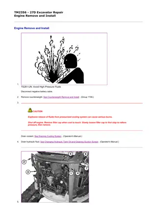
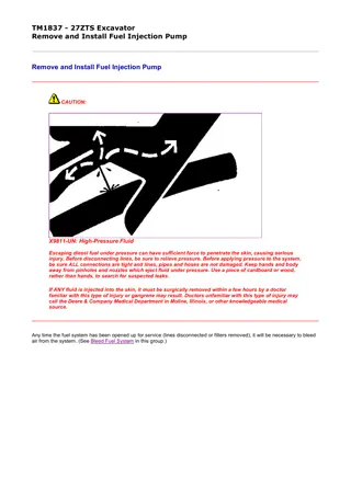
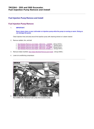
1/7 TM10259 - 17D Excavator Fuel Injection Pump Remove and Install Fuel Injection Pump Remove and Install 1. Remove engine. See Engine Remove and Install . (Group 0400.) 2. IMPORTANT: Never steam clean or pour cold water on injection pump while the pump is running or warm. Doing so can damage the pump. Clean injection lines and area around the injection pump with cleaning solvent or a steam cleaner. 3. IMPORTANT: When loosening fuel supply line connector nuts, use a backup wrench (2) to prevent fuel supply lines from turning. TX1018421A-UN: Fuel Injector Supply Lines at Injection pump LEGEND: 1 - Fuel Supply Line Connector Nut (3 used) 2 - Backup Wrench Loosen fuel supply line connector nuts (1) at fuel injection pump. 4. IMPORTANT: When loosening fuel supply line connector nuts at fuel injector nozzles, use a backup wrench (2) to prevent fuel leak-off lines from turning. Loosen fuel supply line connector nuts at fuel injector nozzles and remove fuel supply lines. Close all openings using caps and plugs. 5. IMPORTANT: Fuel leak-off lines are a one-piece assembly connected to all three fuel injectors. Do not bend or twist the file:///C:/ProgramData/Service%20ADVISOR/Temp/TM10259_09001faa805... 2019/11/15
2/7 fuel leak-off lines when removing. TX1018427-UN: Fuel Leak-Off Line LEGEND: 3 - End of Fuel Leak-Off Return Line Assembly 4 - Fuel Leak-Off Return Line Nut (3 used) 5 - Fuel Leak-Off Return line 6 - Bronze Washer (3 used) Disconnect fuel leak-off return hose from the end of the fuel leak-off return line assembly (3). 6. Remove fuel leak-off return line nuts (4) from each injector. 7. Carefully remove fuel leak-off line (5). Close all openings using caps and plugs. 8. Remove throttle cable from fuel injection pump. 9. Separate the stop solenoid wiring connector. 10. IMPORTANT: The oil supply line has a sealing washer on each side of the fittings. DO NOT lose the sealing washers file:///C:/ProgramData/Service%20ADVISOR/Temp/TM10259_09001faa805... 2019/11/15
3/7 when removing the banjo bolts. Do not reuse sealing washers. Always replace sealing washers with new. TX1019391A-UN: Oil Supply Line LEGEND: 7 - Banjo Bolt for Oil Fitting (cylinder block) 8 - Banjo Bolt for Oil Fitting (injection pump) 9 - Oil Supply Line Remove the banjo bolts for the oil fitting on the cylinder block (7) and on the injection pump (8). Remove oil supply line (9). Discard sealing washers. 11. NOTE: The fuel injection pump gear cover is secured with an adhesive sealant. Use a gasket scraper to separate the fuel injection pump gear cover from the gear case cover. file:///C:/ProgramData/Service%20ADVISOR/Temp/TM10259_09001faa805... 2019/11/15
4/7 TX1019393A-UN: Fuel Injection Pump Gear Cover LEGEND: 10 - Cap Screws (6 used) 11 - Fuel Injection Pump Gear Cover Remove cap screws (10) and fuel injection pump gear cover (11). 12. NOTE: For all the timing marks to become aligned the engine may need to be rotated up to fifty-two times. TX1019400A-UN: Fuel Injection pump Gear Remove LEGEND: 12 - Pump Gear Timing Mark 13 - Idler Gear Timing Mark file:///C:/ProgramData/Service%20ADVISOR/Temp/TM10259_09001faa805... 2019/11/15
5/7 14 - Timing Gear Retaining Nut 15 - Washer 16 - Cap Screw (4 used) 17 - Threaded Puller Holes Rotate the engine in the direction of rotation until the pump gear timing mark (12) aligns with the idler gear timing mark (13). Use chalk or paint to highlight both timing marks. 13. IMPORTANT: Do not loosen or disturb cap screws (16) securing the timing gear to the hub. Gear to hub adjustment is preset to comply with strict EPA emissions requirements and is not adjustable. This procedure is done at the pump manufacturer and cannot be duplicated in the field. Hold the gear train stationary using a large socket wrench on the crankshaft pulley bolt. Loosen the timing gear retaining nut (14) and turn it out to the end of the fuel injection pump shaft, but DO NOT remove. 14. IMPORTANT: Engine must not be rotated when timing gear is removed from injection pump shaft. Engine should only be rotated when timing gear is securely fastened to the pump or engine damage could result. NOTE: The injection pump drive gear and hub can be removed from the gear case; however it is best to let it remain in the gear case, meshed with the idler gear. Remove the fuel injection pump drive gear and hub from the injection pump drive shaft as an assembly using the appropriate puller. Once the fuel injection pump drive gear and hub assembly have popped loose from the tapered fuel injection pump drive shaft, carefully remove the timing gear retaining nut and washer. 15. IMPORTANT: Marks must be made on the injection pump and the gear cover mounting plate to correctly install the pump. If marks are not made, there will be no way to properly time the injection pump. TX1019414A-UN: Timing Marks LEGEND: file:///C:/ProgramData/Service%20ADVISOR/Temp/TM10259_09001faa805... 2019/11/15
6/7 18 - Injection Pump Timing Mark 19 - Gear Cover Mounting Plate Timing Mark Note position of timing marks on injection pump (18) and gear cover mounting plate (19). Pump must be installed at the exact same timing mark as when removed. Scribe a line as accurately and straight as possible, transferring the pump flange mark onto the gear cover mounting plate. 16. IMPORTANT: DO NOT attempt to service the injection pump or governor. If unit is in need of repair, it must be serviced by a qualified EPA/CARB certified fuel injection repair shop. If replacement is necessary, replace entire unit. Do not rotate engine while injection pump is removed. If engine is rotated, the timing gear cover must be removed to ensure correct timing. Remove the three cap screws fastening the fuel injection pump to the gear case. Remove the fuel injection pump. Leave the fuel injection pump drive gear and hub assembly in the gear case, meshed with the idler gear. 17. Install a new O-ring on the injection pump. 18. IMPORTANT: Ensure that the fuel injection pump gear and idler gear timing marks are still in alignment. Install fuel injection pump onto back of gear cover mounting plate. Align key on fuel injection pump drive shaft with keyway in gear hub, ensure that the fuel injection pump drive gear and idler gear timing marks are still aligned. Install three mounting nuts. Do not tighten. 19. Install nut and washer on pump shaft. Hold the gear train stationary using a large socket wrench on the crankshaft pulley bolt. Tighten the timing gear retaining nut to specification. Item Measurement Specification Fuel Injection Pump Drive Gear Hub-to-Shaft Retaining Nut Torque 59 69 N m 44 51 lb-ft 20. Align timing mark on injection pump (18) with scribed mark on gear cover mounting plate. 21. Tighten fuel injection pump mounting nuts to specification. Item Measurement Specification Fuel Injection Pump Mounting Nuts Torque 23 28 N m 17 21 lb-ft. 22. Apply a thin bead of PM38655 Flexible Form-In-Place Gasket to the fuel injection pump gear cover prior to installation. Install pump gear cover and tighten cap screws securely. 23. IMPORTANT: The oil supply line has a sealing washer on each side of the fittings. DO NOT reuse old sealing washers. Always replace with new when removed. Fill the fuel injection pump with clean oil through the external oil supply line port until oil runs out. Install the oil supply line using new sealing washers on both sides of the oil supply line fittings. Install banjo bolts and tighten to specification. Item Measurement Specification Oil Supply Line Banjo Bolt Torque 29 34 N m 22 25 lb-ft. 24. IMPORTANT: file:///C:/ProgramData/Service%20ADVISOR/Temp/TM10259_09001faa805... 2019/11/15
7/7 Fuel leak-off lines are a one-piece assembly connected to all three fuel injectors. DO NOT bend or twist the fuel leak-off lines when Installing. Attach the fuel leak-off return hose to the end of the fuel leak-off return line assembly. 25. Install and tighten fuel leak-off return line nuts at each injector. 26. Install throttle cable to fuel injection pump 27. Reconnect the stop solenoid wiring connector. 28. IMPORTANT: When tightening the fuel supply line connector nuts at the fuel injection pump, use a backup wrench to prevent delivery lines from turning. Tighten fuel supply line connector nuts at fuel injection pump. 29. IMPORTANT: When tightening fuel supply line connector nuts at fuel injector nozzles, use a backup wrench to prevent fuel leak-off lines from turning. Tighten fuel supply line connector nuts at fuel injector nozzles. 30. Install engine. See Engine Remove and Install . (Group 0400.) LOCTITE is a trademark of Henkel Corporation MH66O88,000053D-19-20080923 file:///C:/ProgramData/Service%20ADVISOR/Temp/TM10259_09001faa805... 2019/11/15
Suggest: If the above button click is invalid. Please download this document first, and then click the above link to download the complete manual. Thank you so much for reading
1/4 TM10259 - 17D Excavator Fuel Injection Pump Timing Procedure for New, Rebuilt, or Recalibrated Pumps Fuel Injection Pump Timing Procedure for New, Rebuilt, or Recalibrated Pumps 1. NOTE: The following procedure is performed on the No. 1 cylinder. Checking and adjusting fuel injection timing using the No. 1 cylinder is sufficient; the same procedure may be performed on any or all cylinders. NOTE: Some fuel may drain from the fuel injection pump during this procedure. Contain and dispose of any such fuel spillage. Thoroughly clean the area around the fuel injection pump. 2. NOTE: The stop solenoid must be removed to allow fuel to flow through the fuel injection pump. TX1019517-UN: Stop Solenoid Remove LEGEND: 1 - Stop Solenoid Electrical Connector file:///C:/ProgramData/Service%20ADVISOR/Temp/TM10259_09001faa806... 2019/11/15
https://www.ebooklibonline.com Hello dear friend! Thank you very much for reading. Enter the link into your browser. The full manual is available for immediate download. https://www.ebooklibonline.com

