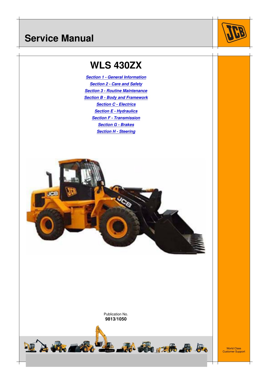
JCB WLS 430ZX Wheeled Loader Service Repair Manual Instant Download
Please open the website below to get the complete manualnn//
Download Presentation

Please find below an Image/Link to download the presentation.
The content on the website is provided AS IS for your information and personal use only. It may not be sold, licensed, or shared on other websites without obtaining consent from the author. Download presentation by click this link. If you encounter any issues during the download, it is possible that the publisher has removed the file from their server.
E N D
Presentation Transcript
Service Manual WLS 430ZX Section 1 - General Information Section 2 - Care and Safety Section 3 - Routine Maintenance Section B - Body and Framework Section C - Electrics Section E - Hydraulics Section F - Transmission Section G - Brakes Section H - Steering Publication No. 9813/1050 World Class Customer Support Copyright 2004 JCB SERVICE. All rights reserved. No part of this publication may be reproduced, stored in a retrieval system, or transmitted in any form or by any other means, electronic, mechanical, photocopying or otherwise, without prior permission from JCB SERVICE. Issued by JCB Technical Publications, JCB Aftermarket Training, Woodseat, Rocester, Staffordshire, ST14 5BW, England. Tel +44 1889 591300 Fax +44 1889 591400
Section 1 - General Information Notes: 1-0 1-0 -
Section 1 - General Information Contents Contents Introduction About this Manual ...................................................................................... 1-1 Machine Model and Serial Number .......................................................1-1 Using this Manual ..................................................................................1-1 Left Side, Right Side ..............................................................................1-1 Cab/Canopy ..........................................................................................1-1 Cross References ..................................................................................1-1 Machine Description .................................................................................. 1-2 The JCB Wheeled Loader .....................................................................1-2 Intended Use .........................................................................................1-2 Component Location .............................................................................1-2 Identifying Your Machine ........................................................................... 1-4 Machine Identification Plate ..................................................................1-4 Page No. Standard Torque Settings Zinc Plated Fasteners and Dacromet Fasteners ....................................... 1-5 Introduction ............................................................................................1-5 Bolts and Screws ...................................................................................1-5 Hydraulic Connections ............................................................................... 1-9 'O' Ring Face Seal System ....................................................................1-9 'Torque Stop' Hose System .................................................................1-12 JCB Standard Torque Settings ................................................................ 1-13 B.S.P. Port Connection (Colour Coded) ..............................................1-13 Hose Ends and Flanged Fittings (Colour Coded) ................................1-14 Service Tools Numerical List .......................................................................................... 1-15 Tool Detail Reference Section B - Body and Framework ........................ 1-16 Numerical List Section C - Electrics ........................................................ 1-20 Tool Detail Reference Section C - Electrics ............................................. 1-21 Numerical List Section E - Hydraulics ..................................................... 1-22 Tool Detail Reference Section E- Hydraulics ........................................... 1-25 Numerical List Section F - Transmission ................................................. 1-28 Tool Detail Reference Section F - Transmission ...................................... 1-29 Numerical List Section K - Engine ........................................................... 1-32 Tool Detail Reference Section K - Engine ............................................... 1-33 Service Consumables Sealing and Retaining Compounds ......................................................... 1-35 Terms and Definitions Colour Coding .......................................................................................... 1-37 Hydraulic Schematic Colour Codes .....................................................1-37 1-i 1-i
Section 1 - General Information Contents Contents Page No. 1-ii 1-ii
https://www.ebooklibonline.com Hello dear friend! Thank you very much for reading. Enter the link into your browser. The full manual is available for immediate download. https://www.ebooklibonline.com
Section 1 - General Information Introduction About this Manual Machine Model and Serial Number Left Side, Right Side This manual provides information for 430ZX Wheel Loading Shovel Model: In this manual, 'left' A and 'right' B mean your left and right when you are seated correctly in the machine. 430ZX (JCB Engine) from 1767600 to 1768499 430ZX (Al Engine) from 2054250 to 2056249 Using this Manual T1-044 This manual is arranged to give you a good understanding of the machine and its safe operation. It also contains maintenance information and specification data. Read this manual from front to back before using the machine for the first time. Particular attention must be given to all the safety aspects of operating and maintaining the machine. T033800-1 Fig 1. If there is anything you are not sure about, ask your JCB distributor or employer. Do not guess, you or others could be killed or seriously injured. Cab/Canopy T1-003_2 This manual frequently makes references to the cab. For instance, 'do not operate the machine without a manual in the cab'. It should be noted that these statements also apply to canopy build machines. General warnings in this chapter are repeated throughout the book, as well as specific warnings. Read all the safety statements regularly, so you do not forget them. Remember that the best operators are the safest operators. Cross References T1-004_2 The illustrations in this manual are for guidance only. Where the machines differ, the text and or the illustration will specify. In this publication, page cross references are made by presenting the subject title printed in bold, italic and underlined. It is preceeded by the 'go to' symbol. The number of the page upon which the subject begins, is indicated within the brackets. For example: K References ( T T 1-1). This manual contains original instructions, verified by the manufacturer (or their authorised representative). K Cross The manufacturer's policy is one of continuous improvement. The right to change the specification of the machine without notice is reserved. No responsibility will be accepted for discrepancies which may occur between specifications of the machine and the descriptions contained in this publication. All optional equipment included in this manual may not be available in all territories. 1-1 1-1 9813/1050
Section 1 - General Information Introduction Machine Description Machine Description The JCB Wheeled Loader P4-1002 Self-propelled wheeled machine with an integral front mounted shovel-supporting structure and linkage, which loads or excavates through forward motion of the machine, and lifts, transports and discharges material. Intended Use The machine is intended to be used under normal conditions for the applications described in this manual. If the machine is used for other purposes or in dangerous environments, for example in a flammable atmosphere or in areas with dust containing asbestos, special safety regulations must be followed and the machine must be equipped for use in these environments. Component Location Loader arms Bucket Cab Engine cover Hydraulic fluid filler point Hydraulic fluid tank sight glass Diesel filler point Articulation lock Battery Battery isolator switch Tool box 1 2 3 4 5 6 7 8 9 10 11 1-2 1-2 9813/1050
Section 1 - General Information Introduction Machine Description 3 4 5 6 11 7, 10 D023796 Fig 2. 1-3 1-3 9813/1050
Section 1 - General Information Introduction Identifying Your Machine Identifying Your Machine Machine Identification Plate Engine Data Plate Each JCB Engine has an emissions legislation lable. K K Fig 4. ( T T 1-4). Your machine has an identification. K K Fig 3. ( T T 1-4). The machine and engine serial numbers can help identify exactly the type of equipment you have. D021990 Fig 4. D021850 Fig 3. Ashok Leyland Engine Data Plate Typical Product Identification Number (PIN) Each Ashok Leyland Engine has a data plate K K Fig 5. ( T T 1-4). 1 2 3 C 4 JCB 430ZX 01801240 World Manufacturer Identification (JCB) 1 Machine Type and Model 2 Randomly Generated Check Letter 3 Machine Serial Number (01801240) 4 D026610 Fig 5. 1-4 1-4 9813/1050
Section 1 - General Information Standard Torque Settings Zinc Plated Fasteners and Dacromet Fasteners Standard Torque Settings Zinc Plated Fasteners and Dacromet Fasteners T11-002 Introduction Bolts and Screws Some external fasteners on JCB machines are manufactured using an improved type of corrosion resistant finish. This type of finish is called Dacromet and replaces the original Zinc and Yellow Plating used on earlier machines. Use the following torque setting tables only where no torque setting is specified in the text. Note: Dacromet fasteners are lubricated as part of the plating process, do not lubricate. The two types of fasteners can be readily identified by colour and part number suffix. K ( T T 1-5). Torque settings are given for the following conditions: K Table 1. Fastener Types Condition 1 Table 1. Fastener Types Colour Un-lubricated fasteners Zinc fasteners Yellow plated fasteners Fastener Type Zinc and Yellow Dacromet Part No. Suffix Golden finish 'Z' (e.g. 1315/3712Z) Condition 2 Mottled silver finish 'D' (e.g. 1315/3712D) Zinc flake (Dacromet) fasteners Lubricated zinc and yellow plated fasteners Where there is a natural lubrication. For example, cast iron components Note: As the Dacromet fasteners have a lower torque setting than the Zinc and Yellow fasteners, the torque figures used must be relevant to the type of fastener. Note: A Dacromet bolt should not be used in conjunction with a Zinc or Yellow plated nut, as this could change the torque characteristics of the torque setting further. For the same reason, a Dacromet nut should not be used with a Zinc or Yellow plated bolt. Verbus Ripp Bolts Note: All bolts used on JCB machines are high tensile and must not be replaced by bolts of a lesser tensile specification. Fig 1. Note: Dacromet bolts, due to their high corrosion resistance are used in areas where rust could occur. Dacromet bolts are only used for external applications. They are not used in applications such as gearbox or engine joint seams or internal applications. Torque settings for these bolts are determined by the application. Refer to the relevant procedure for the required settings. 1-5 1-5 -
Section 1 - General Information Standard Torque Settings Zinc Plated Fasteners and Dacromet Fasteners Table 2. Torque Settings - UNF Grade 'S' Fasteners Hexagon (A/F) in. Nm 7/16 11.2 1/2 22.3 9/16 40.0 5/8 64.0 3/4 98.00 13/16 140.0 15/16 196.0 1 1/8 343.0 1 15/16 547.0 1 1/2 814.0 1 7/8 1181.0 2 1/4 1646.0 Bolt Size Condition 1 kgf m 1.1 2.3 4.1 6.5 10.0 14.3 20.0 35.0 55.8 83.0 120.4 167.8 Condition 2 kgf m 1.0 2.0 3.7 5.8 9.0 12.8 18.0 31.5 50.2 74.6 108.4 151.0 in. 1/4 5/16 3/8 7/16 1/2 9/16 5/8 3/4 7/8 1 1 1/8 1 1/4 mm 6.3 7.9 9.5 11.1 12.7 14.3 15.9 19.0 22.2 25.4 31.7 38.1 lbf ft 8.3 16.4 29.5 47.2 72.3 103.2 144.6 253.0 403.4 600.4 871.1 1214.0 Nm 10.0 20.0 36.0 57.0 88.0 126.0 177.0 309.0 492.0 732.0 1063.0 1481.0 lbf ft 7.4 14.7 26.5 42.0 64.9 92.9 130.5 227.9 362.9 539.9 784.0 1092.3 Table 3. Torque Settings - Metric Grade 8.8 Fasteners Hexagon (A/F) Bolt Size Condition 1 Condition 2 ISO Metric Thread M5 M6 M8 M10 M12 M16 M20 M24 M30 M36 mm 5 6 8 10 12 16 20 24 30 36 mm 8 10 13 17 19 24 30 36 46 55 Nm 5.8 9.9 24.0 47.0 83.0 205.0 400.0 690.0 1372.0 2399.0 kgf m 0.6 1.0 2.4 4.8 8.5 20.9 40.8 70.4 139.9 244.6 lbf ft 4.3 7.3 17.7 34.7 61.2 151.2 295.0 508.9 1011.9 1769.4 Nm 5.2 9.0 22.0 43.0 74.0 184.0 360.0 621.0 1235.0 2159.0 kgf m 0.5 0.9 2.2 4.4 7.5 18.8 36.7 63.3 125.9 220.0 lbf ft 3.8 6.6 16.2 31.7 54.6 135.7 265.5 458.0 910.9 1592.4 1-6 1-6 -
Section 1 - General Information Standard Torque Settings Zinc Plated Fasteners and Dacromet Fasteners Table 4. Metric Grade 10.9 Fasteners Hexagon (A/F) Bolt Size Condition 1 Condition 2 ISO Metric Thread M5 M6 M8 M10 M12 M16 M20 M24 M30 M36 mm 5 6 8 10 12 16 20 24 30 36 mm 8 10 13 17 19 24 30 36 46 55 Nm 8.1 13.9 34.0 67.0 116.0 288.0 562.0 971.0 1930.0 3374.0 kgf m 0.8 1.4 3.5 6.8 11.8 29.4 57.3 99.0 196.8 344.0 lbf ft 6.0 10.2 25.0 49.4 85.5 212.4 414.5 716.9 1423.5 2488.5 Nm 7.3 12.5 30.0 60.0 104.0 259.0 506.0 874.0 1737.0 3036.0 kgf m 0.7 1.3 3.0 6.1 10.6 26.4 51.6 89.1 177.1 309.6 lbf ft 5.4 9.2 22.1 44.2 76.7 191.0 373.2 644.6 1281.1 2239.2 Table 5. Metric Grade 12.9 Fasteners Hexagon (A/F) Bolt Size Condition 1 Condition 2 ISO Metric Thread M5 M6 M8 M10 M12 M16 M20 M24 M30 M36 mm 5 6 8 10 12 16 20 24 30 36 mm 8 10 13 17 19 24 30 36 46 55 Nm 9.8 16.6 40.0 80.0 139.0 345.0 674.0 1165.0 2316.0 4049.0 kgf m 1.0 1.7 4.1 8.1 14.2 35.2 68.7 118.8 236.2 412.9 lbf ft 7.2 12.2 29.5 59.0 102.5 254.4 497.1 859.2 1708.2 2986.4 Nm 8.8 15.0 36.0 72.0 125.0 311.0 607.0 1048.0 2084.0 3644.0 kgf m 0.9 1.5 3.7 7.3 12.7 31.7 61.9 106.9 212.5 371.6 lbf ft 6.5 11.1 26.5 53.1 92.2 229.4 447.7 773.0 1537.1 2687.7 1-7 1-7 -
Section 1 - General Information Standard Torque Settings Zinc Plated Fasteners and Dacromet Fasteners Table 6. Torque Settings - Rivet Nut Bolts/Screws Bolt Size ISO Metric Thread mm M3 3 M4 4 M5 5 M6 6 M8 8 M10 10 M12 12 Nm 1.2 3.0 6.0 10.0 24.0 48.0 82.0 kgf m 0.1 0.3 0.6 1.0 2.5 4.9 8.4 lbf ft 0.9 2.0 4.5 7.5 18.0 35.5 60.5 Table 7. Torque Settings - Internal Hexagon Headed Cap Screws (Zinc) Bolt Size ISO Metric Thread M3 2.0 M4 6.0 M5 11.0 M6 19.0 M8 46.0 M10 91.0 M12 159.0 M16 395.0 M18 550.0 M20 770.0 M24 1332.0 Nm kgf m 0.2 0.6 1.1 1.9 4.7 9.3 16.2 40.0 56.0 79.0 136.0 lbf ft 1.5 4.5 8.0 14.0 34.0 67.0 117.0 292.0 406.0 568.0 983.0 1-8 1-8 -
Section 1 - General Information Standard Torque Settings Hydraulic Connections Hydraulic Connections T11-003 'O' Ring Face Seal System Adaptors Screwed into Valve Blocks Adaptor screwed into valve blocks, seal onto an 'O' ring which is compressed into a 45 seat machined into the face of the tapped port. Table 8. Torque Settings - BSP Adaptors BSP Adaptor Size in. mm 1/4 19.0 3/8 22.0 1/2 27.0 5/8 30.0 3/4 32.0 1 38.0 1 1/4 50.0 Hexagon (A/F) Nm 18.0 31.0 49.0 60.0 81.0 129.0 206.0 kgf m 1.8 3.2 5.0 6.1 8.2 13.1 21.0 lbf ft 13.0 23.0 36.0 44.0 60.0 95.0 152.0 Table 9. Torque Settings - SAE Connections Hexagon (A/F) mm 15.9 20.0 - 28.0 19.1 46.0 - 54.0 22.2 95.0 - 105.0 27.0 130.0 - 140.0 1 1/16 - 12 31.8 1 5/16 - 12 38.1 1 5/8 47.6 SAE Tube Size 4 6 8 10 12 16 20 SAE Port Thread Size 7/16 - 20 9/16 - 18 3/4 - 16 7/8 - 14 Nm kgf m 2.0 - 2.8 4.7 - 5.5 9.7 - 10.7 13.2 - 14.3 19.4 - 21.4 29.6 - 31.6 28.5 - 38.7 lbf ft 16.5 - 18.5 34.0 - 40.0 69.0 - 77.0 96.0 - 104.0 141.0 - 155.0 216.0 - 230.0 210.0 - 280.0 190.0 - 210.0 290.0 - 310.0 280.0 - 380.0 1-9 1-9 -
Section 1 - General Information Standard Torque Settings Hydraulic Connections Hoses Screwed into Adaptors Fig 2. Hoses 2-B screwed into adaptors 2-A seal onto an `O' ring 2-C which is compressed into a 45 seat machined into the face of the adaptor port. Note: Dimension 2-D will vary depending upon the torque applied. Table 10. BSP Hose - Torque Settings Hexagon (A/F) mm 14.0 14.0 - 16.00 19.0 24.0 - 27.0 22.0 33.0 - 40.0 27.0 44.0 - 50.0 30.0 58.0 - 65.0 32.0 84.0 - 92.0 38.0 115.0 - 126.0 50.0 189.0 - 200.0 55.0 244.0 - 260.0 BSP Hose Size in. 1/8 1/4 3/8 1/2 5/8 3/4 1 1 1/4 1 1/2 Nm kgf m 1.4 - 1.6 2.4 - 2.7 3.4 - 4.1 4.5 - 5.1 5.9 - 6.6 8.6 - 9.4 11.7 - 12.8 19.3 - 20.4 24.9 - 26.5 lbf ft 10.3 - 11.8 17.7 - 19.9 24.3 - 29.5 32.4 - 36.9 42.8 - 47.9 61.9 - 67.8 84.8 - 92.9 139.4 - 147.5 180.0 - 191.8 1-10 1-10 -
Section 1 - General Information Standard Torque Settings Hydraulic Connections Adaptors into Component Connections with Bonded Washers Table 11. BSP Adaptors with Bonded Washers - Torque Settings BSP Size Nm in. 1/8 20.0 1/4 34.0 3/8 75.0 1/2 102.0 5/8 122.0 3/4 183.0 1 203.0 1 1/4 305.0 1 1/2 305.0 kgf m 2.1 3.4 7.6 10.3 12.4 18.7 20.7 31.0 31.0 lbf ft 15.0 25.0 55.0 75.0 90.0 135.0 150.0 225.0 225.0 1-11 1-11 -
Section 1 - General Information Standard Torque Settings Hydraulic Connections 'Torque Stop' Hose System Fig 3. `Torque Stop' Hoses 3-B screwed into adaptors 3-A seal onto an 'O' ring 3-C which is compressed into a 45 seat machined in the face of the adaptor port. To prevent the 'O' ring being damages as a result of over tightening, 'Torque Stop' Hoses have an additional shoulder 3-D, which acts as a physical stop. Note: Minimum dimension 3-E fixed by shoulder 3-D. Table 12. BSP `Torque Stop' Hose - Torque Settings BSP Hose Size Hexagon (A/F) in. mm 1/8 14.0 1/4 19.0 3/8 22.0 1/2 27.0 5/8 30.0 3/4 32.0 1 38.0 1 1/4 50.0 1 1/2 55.0 Nm 14.0 27.0 40.0 55.0 65.0 95.0 120.0 189.0 244.0 kgf m 1.4 2.7 4.1 5.6 6.6 9.7 12.2 19.3 24.9 lbf ft 10.0 20.0 30.0 40.0 48.0 70.0 89.0 140.0 180.0 1-12 1-12 -
Section 1 - General Information Standard Torque Settings JCB Standard Torque Settings JCB Standard Torque Settings B.S.P. Port Connection (Colour Coded) Note: All adapters, elbows and hoses should be tightened to JCB standard torque settings unless stated otherwise. Fig 4. 1-13 1-13 -
Section 1 - General Information Standard Torque Settings JCB Standard Torque Settings Hose Ends and Flanged Fittings (Colour Coded) Note: All adapters, elbows and hoses should be tightened to JCB standard torque settings unless stated otherwise. Fig 5. 1-14 1-14 -
Section 1 - General Information Service Tools Numerical List The tools listed in the table are special tools required for carrying out the procedures described in this manual. These tools are available from JCB Service. details of all tools, including the content of kits and sets, refer to Tool Detail Reference, Section 1. Note: Tools other than those listed will be required. It is expected that such general tools will be available in any well equipped workshop or be available locally from any good tool supplier. Some tools are available as kits or sets, the part numbers for parts within such kits or sets are not listed here. For full Part Number 825/99849 825/99850 826/01179 826/01106 826/01177 826/01176 826/01333 892/00842 892/00843 892/00844 892/00846 892/00847 892/00848 892/00849 926/15500 992/12800 992/12801 Description Tool Detail Reference K Fig 12. ( T K Fig 12. ( T K Fig 1. ( T K Fig 1. ( T K Fig 1. ( T K Fig 1. ( T K Fig 1. ( T K Fig 3. ( T K Fig 2. ( T K Fig 11. ( T K Fig 8. ( T K Fig 4. ( T K Fig 6. ( T K Fig 10. ( T K Fig 5. ( T K Fig 7. ( T K Fig 9. ( T Dummy Boss Bearing Locator M6 x 16mm Rivet Nut M6 x 19mm Rivet Nut M8 x 18mm Rivet Nut M10 x 23mm Rivet Nut M10 x 26mm Rivet Nut Glass Lifter Glass Stand Long Knife Glass Extractor (Handles) Nylon Spatula Wire Starter Braided Cutting Wire Rubber Spacer Blocks Cut-Out Knife 'L' Blades T 1-18) T 1-18) T 1-16) T 1-16) T 1-16) T 1-16) T 1-16) T 1-16) T 1-16) T 1-18) T 1-17) T 1-16) T 1-17) T 1-18) T 1-17) T 1-17) T 1-18) K K K K K K K K K K K K K K K K K 1-15 1-15 -
Section 1 - General Information Service Tools Tool Detail Reference Section B - Body and Framework Tool Detail Reference Section B - Body and Framework Note: essential for preparing new glass prior to installation. Fig 1. Fig 3. 892/00842 Note: 826/01179 M6 x 16mm Rivet Nut, 826/01106 M6 x 19mm Rivet Nut, 826/01177 M8 x 18mm Rivet Nut, 826/01176 M10 x 23mm Rivet Nut, 826/01333 M10 x 26mm Rivet Nut Installation Tool Available from: Bollhoff Fastenings Ltd. Midacre The Willenhall Estate Rose Hill Willenhall West Midlands, WV13 2JW Note: - minimum 2 off - essential for glass installation, 2 required to handle large panes of glass. Ensure suction cups are protected from damage during storage. Fig 4. 892/00847 Note: - general tool used for smoothing sealants - also used to re-install glass in rubber glazing because metal tools will chip the glass edge. Fig 2. 892/00843 1-16 1-16 -
Suggest: If the above button click is invalid. Please download this document first, and then click the above link to download the complete manual. Thank you so much for reading
Section 1 - General Information Service Tools Tool Detail Reference Section B - Body and Framework Fig 5. 926/15500 Fig 7. 992/12800 Note: - used to provide the correct set clearance between glass edge and cab frame. (unit quantity = 500 off) Note: - used to remove broken glass. Fig 8. 892/00846 Note: - used with braided cutting wire (below) to cut out broken glass. Fig 6. 892/00848 Note: - used to access braided cutting wire (below) through original polyurethane seal. 1-17 1-17 -
https://www.ebooklibonline.com Hello dear friend! Thank you very much for reading. Enter the link into your browser. The full manual is available for immediate download. https://www.ebooklibonline.com

![JCB TM180, TM220 [Engine Deutz] Telescopic Wheeled Loader Service Repair Manual Instant Download](/thumb/98308/jcb-tm180-tm220-engine-deutz-telescopic-wheeled-loader-service-repair-manual-instant-download.jpg)
