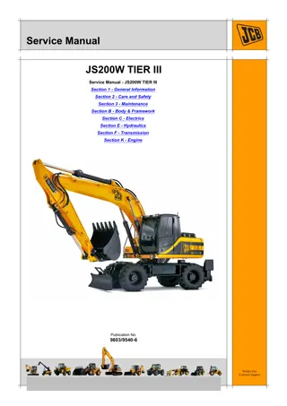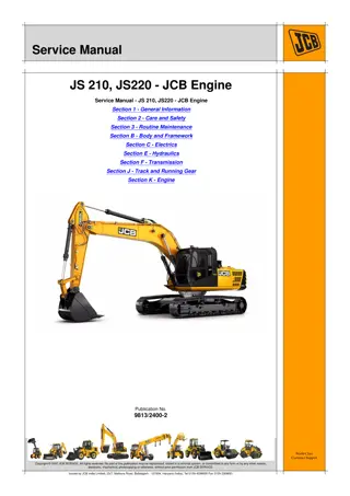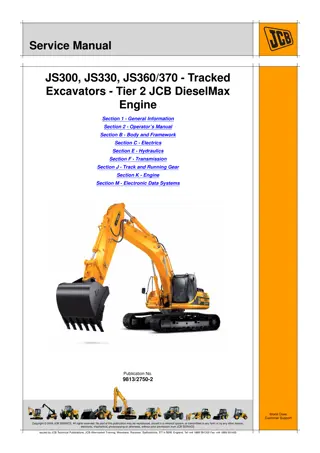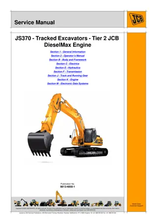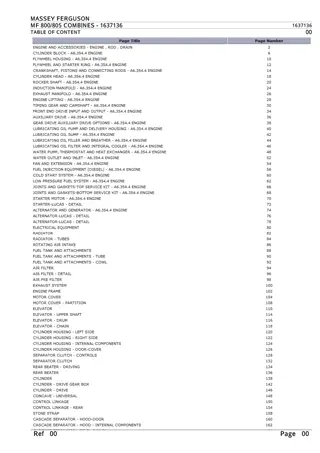
JCB 805, 805B, 806B, 807B, 808 Excavator Service Repair Manual Instant Download
Please open the website below to get the complete manualnn//
Download Presentation

Please find below an Image/Link to download the presentation.
The content on the website is provided AS IS for your information and personal use only. It may not be sold, licensed, or shared on other websites without obtaining consent from the author. Download presentation by click this link. If you encounter any issues during the download, it is possible that the publisher has removed the file from their server.
E N D
Presentation Transcript
SERVICE MANUAL ' ~ I \ [} ., ) ~ \ l r ) ' r \ , 1 r .,., ,_, ) ) f \ r ~ _ , ) r .. 1 / , , l_j ' r i. ) I I I @ JCB SERVICE ROCESTER, STAFFORDSHIRE, ST14 5LS. ENGLAND. ~ ( I l I 1 ; J TEL. AOCESTER (0889) 590312 Printed 'in England.
-.- 'l : r,t ,1 : Contents : tl l" tl /. \ t. General ( 1 Hydraulics 2 3 Attachments Body & Framework 4 5 Gearboxes Track & Running Gear 6 7 I Engine Electrics lndex {. I I I I 9803/3tt l oue 1 \|.
/r------n r tl -) ' I ( lr {t l, 805,8058 8068,8078 I\) I 808 1 I ._i Publication No. 9803/3150
https://www.ebooklibonline.com Hello dear friend! Thank you very much for reading. Enter the link into your browser. The full manual is available for immediate download. https://www.ebooklibonline.com
r' { I \ I Introduct on i {\ il This publication is designed for the benefit of JCB Distributor Service Engineers who are receiving, or have received training by the JCB Technical Training Department. It is assumed that such personnel have at least a sound knowledge of workshop practice, safety procedures and general techniques assoc ated with the maintenance and repair of hydraulic earthmoving equipment. Details of such are therefore generally omitted from this manual, the intention being to convey only the more specialised information concerning particular aspects of the machine or component in question. ) For example, renewal of oil seals, gaskets etc. and any component showing obvious wear or damage is expected as a matter of course and information on these matters is therefore only included where a specialised procedure or range of wear tolerances is required. Similarly, it is expected that components will be thoroughly cleaned and lubricated where appropriate, also that any opened hose or pipe connections will be blanked to prevent entry of dirt and excessive loss of hydraulic fluid. l 1. For convenience the manual is compiled in sections, e.g. "Hydraulics", "Gearboxes" etc., but to find details of a specific component, reference should be made to the alphabet cal index at the back of the book. lllustrations showing a dismantled component are numbered as a guide to the dismantling sequence which can generally be reversed for assembly. Torque settings quoted are given as'mean'figures which may be varied by i g . 'Left Hand'and 'Right Hand'are as viewed from the rear of the machine. i Replacement or additional pages for this manual will be issued from t me to time and should be inserted in place of the existing pages which should be removed and destroyed. Where possible, revised pages will bear an asterisk (*) against the new information, the page issue number in the bottom right hand corner being similarly marked. A Service Tools Catalogue, detailing special tools required, is available separately .1
General 1 1 3-1 3-1 ) \ GREASE POINTS ALL PIVOT PINS 10 Hours EACH SLEWING RING NIPPLE AND ROTARY COUPLING * 4 shots ) 50 Hours ) SLEW]NG RING TEETH Repack 1600 Hours 0 !./ \ tl- ( { I 9803/3150 lssu.e 2t {
f'\ f--' General 1 1 3-2 3-2 GREASE POINTS ALL PIVOT PI NS 10 Hours EACH SLEWING RING NIPPLE AND ROTARY COUPLING 4 shots 50 Hours SLEWING R ING TEETH Repack 1600 Hours SLIDING BEAM Grease as required t I\ 48674 i. lssue 3 9803/31 50
n 2 Hydraulics 2 2-1 2-1 e, FILTER OPERATION (^' lr l-. l- Ne (o --E -l- 1 ( l- ( ( ( ( ( ( t_ L, L L U U U lssue 3 9803/31 50 l._- \
2 Hydraulics 2 2-2 2-2 HYDRAULIC FITTER (Early Type) RENEW ELEMENT 400 Hours EveTy Carefully remove hydraulic oil filler cap4 1 Remove plug B to prevent excess loss of f luid. 2 3 Remove U-bolt C. 4 Unscrew bolt D until body can be withdrawn. A considerable amount of fluid will flow from the filter at this stage. Note: Remove bolt , body, and element F. 5 G> Wash all metal parts in JCB'Special' Hydraulic Fluid. 6 7 Re-assemble using new element and seal F. I I Repeat for second filter Top up at filler cap. 2856A ( 9803/31 50 lssue 3
n a a 2 Hydraulics 2 2-3 2-3 HYDRAULIC FILTER (Later Type) ( ( Renew Element EverY 400 Hours. To prevent siphoning of tank when draining filter, remove tank filler cap and filter Plug A. ( 2. Drain filter at plug C. Note: On 805,8068,8078 and 808 Remove access plate B. ( Unscrew bolt D (nut D on later 8058) and element E 3. Wash all metal parts in JCB 'Special' Hydraulic Fluid. 4. Reassemble using new element and seal F which should be lu bricated before f itting. 5. ( 6. Top up hydraulic tank. ( ( ( re ( \ t (, (_-, L, (_) lssue 1 9803/31 50 I
I 2 Hydraulics 2 3-1 3-1 PUMP OPERATION I I oFe @ ) l I - tt I \ \l t 9803/31 50 lssue 2 t1
n' 2 2 Hydraulics 4-1 4-1 l_- MOTOR OPERATION (-'. @ Noo a-. r-' a' l'' (-' ( ( D ( ( ( \. L L L ( ( lssue 2 9803/3 r 50
1r Hydraulics 2 2 { 5-1 5-1 65 q* 55 @ ) il-ez ) 60 ( 57 46 67 31 24 a c o 4 21 14 I 5 q 1 2 33138 ,) lssue 1 9803/31 50 I
o Hydraulics 2 2 5-2 5-2 e, PUMPS & MOTORS (HAMWORTHY) C, l-t r- r- ft Dismantling and Assembly * NOTE: Main illustration shows a typical three sect on pump with alternative later type wear plates at A. For clarity, pipe connections have been omitted from centre pump section 25. Motors have only one pair of gears with the wear plate and seal arrangement shown at B; otherwise construction is similar. 0.05mm. (0.002in.) below face of bearing bore. Renew wear plates 5,9,26,30, 49 and 53 if scored or eroded. Ensure that all wear plates are f tted with their slots correctly positioned relative to the gears and to the suction and pressure ports as shown. Plates 9, 30 and 53 must fit fully home in the housings and move freely. ( When Dismantling Ensure that seal supports 7, 11, 28,32,51 and 55 also seals 6, 10, 27,31,50 and 54 are correctly trimmed and do not become trapped between wear plates and housing wall. Mark housings and end covers to ensure correct re-assembly. Use a soft faced hammer to part components. Do not use levers or machined surfaces may be damaged. lf the original gears are refitted, align the marks made during dismantling. Mark adjacent teeth of gears with indelible ink before removal. Retain gears in pairs. (' ( Torque Settings Use Service Tool 8T2464 to withdraw bearings 12, 21,35, 45, 58 and 65. lbf ft 31 120 31 120 120 kgf m 4.3 17 4.3 17 17 Item Nm 42 163 42 163 163 1 2 Remove sharp edges, burrs and light scoring from gears, shafts and housings. Use a fine abrasive stone. Wash off any grit or metal particles with clean hydraulic fluid. 22 24 47 t, When Assembling Renew any pair of gears if:- a) Journal area of shaft is pitted or worn in excess of 0.025mm. (0.001 in.). b) Keyway, splines or gears are badly worn or cracked [$ L,, t) L) U U rBe 433't3 Renew bearings if worn or if gears are renewed. They must fit flush with or not more than 9803/31s0 lssue 2+ li
2 Hydraulics 2 5-3 5-3 \\ A 29 42 J e At 38 36 % A I 12 J 31 43 40 43 42 35 4 + 18 b 26 43 42q, @ 1l 41 %@ @ 42 lt 4 ( 8 A 38 l ( ) @ ( 3 42 % () 43 q, 6 @ 9 (l 41664 ( lssue 1 9803/3150 {
2 Hydraulics 2 5-4 5-4 *PUMPS & MOTORS {COMMERCIAL} Dismantling and Assembly *NOTE: lllustration shows an 805/8068 pump. Other pumps have an additional bearing housing 10 in place of adapter flanges 18 and 20. Motors have only one pair of gears, otherwise construct on is similar Renew gears if pitted, scored or chipped or if wear on shaft diameter exceeds 0.05mm. (0.002in.). Shaft wear is most likely on the contact area of ring seals 39. Wear on gear teeth width must not exceed 0.025mm. (0.001 in.) below the nominal size of 1.000in. (25.40mm), 1.250in. (31.75mm) or 1.500in, (38.1Omm). When renewing gears, fit in matched pairs and renew the bearings. When Dismantling Mark housings and end covers to ensu re correct replacement. When separat ng these components, take care to avoid damage to the machined faces. lnstall new ring seals 39 with notched faces towards the bearings. See page 2/5-5 for installation of pocket seals A. lnstall lip seal 37 (also 23 and 26 where fitted) facing in the direction shown. Press items 23 and 26 to the bottom of recess and item 37 flush with surface. Secure with Loctite 222. Before removing gears, mark adjacent teeth with indelible ink to ensure correct replacement. Do not centre punch or stamp. Retain gears in pairs. Check gear housings 5, 13 and 29 for wear as at B. lf gear cut-out exceeds 0.1 2mm. (0.005in.), the housing must be renewed. Torque Settings Item Nm. kgf m 1t Tfll 27o 2s rle I Use extractor MD956 (see Service Tools catalogue) to remove bearings 38. Bearings should bea light press fitin their bores. Loose bearings may indicate worn bores. lbf ft 200 tNote: ltems 17 and 19 are not used on 8078 and 808. *Check security of plug(s) 40. Only remove if damaged, noting position for re-assemblY. When Assembling Q Remove burrs and sharp edges from splines, shafts and housings, using a fine abrasive stone. \(J\ (J (-, C) Renew wear plates 3,9,11,16, 28 and 33 if worn to a thickness of less than 9.47mm.(0.373in.), or if scored, eroded or pitted. *On pumps, Posit on the Presure relief groove towards the high pressure side (see page2/5-51. O ) ^$ N) $s lssue 2t 9803/3150
Hydraulics 2 2 5-5 5-5 PUMPS AND MOTORS (Commercial) Pocket Seal Fitting I The following instructions apply when fitting seals to all thrust plates. 0I Cut two centre-seals to a length of 5.5mm. (O.22in.l Coat the seals with grease and insert into the centre slots of the thrust plate as at A. Place thrust plate,seals facing downwards, into position over the bearings as at B and tap with a soft hammer until clearance between thrust plate and housing is approximately 0.8mm (0.030 in.). Note: On pumps the pressure relief groove X must be towards the high pressure side, (J (J Cut four seals to an approximate length of 6.5mm. (0.25in.). TJ --/ Push the seals into the radial slots as at C until contact is made with the bearings. Tap the thrust plate firmly down against the machined surface. Use a sharp razor blade to trim the exposed ends of the seals until they are square and flush with the thrust plates. <,) c) Q 21,6t (. t 9803/3150 lssue 1
t Hydraulics ( 2 2 6-1 6-1 ( CIRCUIT OPERATION ( When the spool is in the neutral position oil from the pump passes through the centre or neutral circuit of the valve. ( lf a service is selected bY moving the spool either up or down, the neutral circuit is blocked bY the spool. The oil then f lows into the parallel gallery, past the non-return valve'Aand through the open port to the ram or motor. ( { Simultaneously, oi I returning f rom the ram or motor enters the valve block, passes into the exhaust gallery and so back to tank. { f { 30434 t 9803/31 50 I ssue 1
2 Hydraulics 2 6-2 6-2 CIRCUIT OPERATION The illustration on the previous page shows the parallel gallery fed directly from the neutral gallery. Where several spools are housed within one block however, each spool is supplied by a common parallel gallery A running the length of the valve block. The parallel gallery itself is fed from the neutral gallery upstream of the first spool as shown. Alternatively it may be fed from outside the block by means of a High Pressure Carry-over line as described later. More than one spool may thus be operated at any one time. f -- -' ,-/ --' 3(X4A 9803/31 50 lssue I
tl l-l f, Hydraulics 2 2 6-3 6-3 STANDARD SPOOL OPE RATION The standard spool is used in conjunction with a non"return valve to operate a service where back- pressure in the service line will occur due to a gravity loading opposing the action of the ram. l) (--\ ir ti(lia Example: ln the upper illustration the dipper ram spool is being selected but, due to the loaded bucket , the back- pressure in the ram feed line is greater than the PumP output pressure in the parallel gallery at'B'. This higher pressure causes the non- return valve'C'to remain closed, preventing the possibility of reverse oil flow which would allow the load to drop. ( ( ( When the spool is fullY selected, the neutral circuit'D' is ccmpletely cut off and the pressure rises in the paral lel gallery'E'until it exceeds that in the ram feed line. At this point the non-return valve 'F'oPens, permitting oil to flow to the ram and so raise the load. The use of non-return valves also prevents interaction between spools. For example, if non-return valves were not f ttd and two loads were being raised simultaneouslY, the heavier of the two loads would fall and oil from that ram would flow to the more lightlY loaded ram and increase its lifting speed. With non-return valves in the system however, the oil s Prevented from flowing from one service to another. ( ( (. (. ( 30454 ( t; U lssue 1 9803/31 50 l._,'
2 Hydraulics 2 6-4 6-4 MOTOR SPOOL (HUSCO}WITH BRAKE VENT VALVE $ Motor circuits are subject to 'reverse pressure' hydraulic conditions created by the tendency of the driven load to'overrun'. The control valve spool is therefore designed such that, when set to the neutral position, both motor ports are vented to low pressure. J c Example Under slewing conditions, the superstructure of an excavator attains considerable momentum. This causes the mass to 'run on' after the control lever has been reset to neutral. When this occurs the motor'A' acts as a pump (being driven by the load through the slewing gears) and excessively high pressure would be developed if the oil could not escape to exhaust. The pressure would also tend to hold off the automat c brake 'B'. Method of Operation When a service is selected, the main spool blocks the neutral circuit and diverts oil into the parallel gallery, through the open port to one side of motor, a reduced f low also passes through restrictor'E' to release the automat c brake. Shuttle valve 'C' prevents short circuiting of the motor by the brake supply. Exhaust oil from the motor returns to the valve block low pressure gallery. As the control lever is returned to neutral, both motor ports are opened to exhaust. Any pressure which might be generated by the motor s therefore safely dissipated. Brake Vent valve 'D' also opens to provide a direct route to tank for oil from the brake, thus ensuring rapid brake application. 39594 9803/31 50 lssue 1
Suggest: If the above button click is invalid. Please download this document first, and then click the above link to download the complete manual. Thank you so much for reading
r-l TELEFAX MESSAGE 2. F & 2 Pld A n: Cotttp rly: I { 6-5 a 6-5 - Dat : Fpm: D Pt ComP nY: F r. 3 4 5 6 l 19 18 -) ') ) 5 4 ) 16 I ) 23 ) ) 14 13 ) l ) 9 ) 5310 16 14 13 I ) 15 2 ) 1 ,) ,_) -J I ssue 1 9803/3150 l*J
https://www.ebooklibonline.com Hello dear friend! Thank you very much for reading. Enter the link into your browser. The full manual is available for immediate download. https://www.ebooklibonline.com

