Friction Clutches in Power Transmission


FIRST SEMESTER
FIRST SEMESTER
CHAPTER FOUR
CHAPTER FOUR
Friction Clutches
Friction Clutches
Dr. Adil ABed Nayeeif
Dr. Adil ABed Nayeeif
2019-2020
2019-2020
Friction Clutches
Friction Clutches
A friction clutch has its principal application in the transmission of power of shafts and
machines which must be
started and stopped frequently. The force of friction is used to start the driven shaft from rest and gradually brings it up
to the proper speed without excessive slipping of the friction surfaces. In automobiles, friction clutch is used to connect
the engine to the driven shaft. In operating such a clutch, care should be taken so that the friction surfaces engage
easily and gradually brings the driven shaft up to proper speed. The proper alignment of the bearing must be
maintained and it should be located as close to the clutch as possible. It may be noted that.
1.
The contact surfaces should develop a frictional force that may pick up and hold the load with reasonably low
pressure between the contact surfaces.
2.
The heat of friction should be rapidly dissipated and tendency to grab should be at a minimum.
3.
The surfaces should be backed by a material stiff enough to ensure a reasonably uniform distribution of pressure.
The friction clutches of the following types are important from the subject point of view :
i.
Disc or plate clutches (single disc or multiple disc clutch),
ii.
Cone clutches, and
iii.
Centrifugal clutches.
Single Disc or Plate Clutch
Single Disc or Plate Clutch
A single disc or plate clutch, as shown in
Figure(1)
, consists of a clutch plate whose both sides are faced with a friction
material (usually of Ferrodo). It is mounted on the hub which is free to move axially along the splines of the driven
shaft. The pressure plate is mounted inside the clutch body which is bolted to the flywheel. Both the pressure plate and
the flywheel rotate with the engine crankshaft or the driving shaft. The pressure plate pushes the clutch plate towards
the flywheel by a set of strong springs which are arranged radially inside the body. The three levers (also known as
release levers or fingers) are carried on pivots suspended from the case of the body.
The axial pressure exerted by the spring provides a frictional force in the
circumferential direction when the relative motion between the driving
and driven members tends to take place .
If the torque due to this frictional
force exceeds the torque to be transmitted, then no slipping takes place
and the power is transmitted from the driving shaft to the driven shaft.
Figure(1)
Now consider two friction surfaces, maintained in contact by an axial thrust
W
, as shown in
Figure (2).
T
= Torque transmitted by the clutch,
p
= Intensity of axial pressure with which the contact surfaces are held together,
r
1
and r
2
= External and internal radii of friction faces, and
μ =
Coefficient of friction.
Consider an elementary ring of radius r and thickness d
r
as shown in
Figure (2)
We know that area of contact surface or friction surface,
= 2 π
r.dr
∴
Normal or axial force on the ring, or axial force on the ring,
δW = Pressure × Area = p × 2 π r.dr
and the frictional force on the ring acting tangentially at radius r,
Fr =
μ.δ
W =
μ.
p × 2
π
r.dr
∴
Frictional torque acting on the ring,
Tr = Fr × r =
μ.
p × 2
π
r.dr × r = 2
π × μ .
p.r
2
dr
We shall now consider the following two cases :
1.
When there is a uniform pressure, and
2.
When there is a uniform wear.
Figure (2)
Considering uniform pressure
Considering uniform pressure
When the pressure is uniformly distributed over the entire area of the friction face, then the intensity of
pressure,
……(1)
where :
W
= Axial thrust with which the contact or friction surfaces are held together.
We have discussed above that the
frictional torque
on the elementary ring of radius
r
and thickness
dr
is
Tr = 2
π μ.
p.r
2
dr
Integrating this equation within the limits from
r
2
to
r
1
for the total frictional torque .
∴
Total frictional torque acting on the friction surface or on the clutch,
Substituting the value of
p
from equation
(1)
,
where
R
= Mean radius of friction surface,
Considering uniform wear
Considering uniform wear
In
Figure (2)
, let
p
be the normal intensity of pressure at a distance
r
from the axis of the clutch. Since the
intensity of pressure varies inversely with the distance, therefore;
p.r. = C (a constant) or p = C/r …… (1)
and the normal force on the ring,
∴
Total force acting on the friction surface,
We know that the frictional torque acting on the ring,
∴
Total frictional torque on the friction surface,
R = Mean radius of the friction surface,
Multiple Disc Clutch
Multiple Disc Clutch
A multiple disc clutch, as shown in
Figure (3)
, may be used when a large torque is to be transmitted. The
inside discs (usually of steel) are fastened to the driven shaft to permit axial motion (except for the last disc).
The outside discs (usually of bronze) are held by bolts and are fastened to the housing which is keyed to the
driving shaft. The multiple disc clutches are extensively used in motor cars, machine tools etc.
Let
n
1
= Number of discs on the driving shaft, and
n
2
= Number of discs on the driven shaft.
∴
Number of pairs of contact surfaces,
and total frictional torque acting on the friction surfaces or on the clutch,
T = n.
μ.
W.R
where
R
= Mean radius of the friction surfaces,
(For uniform pressure )
(For uniform wear )
Figure (3)
n
=
n
1
+
n
2
– 1
Cone Clutch
Cone Clutch
A cone clutch, as shown in
Figure (4)
, was extensively used in automobiles but now-a-days it has been
replaced completely by the disc clutch.
It consists of one pair of friction surface only. In a cone clutch, the driver is keyed to the driving shaft by a sunk
key and has an inside conical surface or face which exactly fits into the outside conical surface of the driven.
Due to the frictional resistance set up at this contact surface, the torque is transmitted from one shaft to another
In some cases, a spring is placed around the driven shaft in contact with the hub of the driven.
Figure (4)
Consider a pair of friction surface as shown in
Figure (
5
)
. Since the area of contact of a pair of friction surface is a frustrum
of a cone, therefore the torque transmitted by the cone clutch may be determined in the similar manner as discussed for
conical pivot bearings.
p
n
= Intensity of pressure with which the conical friction surfaces are held together (i.e. normal pressure between contact
surfaces),
r
1
and
r
2
= Outer and inner radius of friction surfaces respectively.
R
= Mean radius of the friction surface,
α
= Semi angle of the cone (also called face angle of the cone) or the angle of the friction surface with the axis of the clutch,
μ
= Coefficient of friction between contact surfaces, and
b = Width of the contact surfaces (also known as face width or clutch face).
Figure (
5
)
Consider a small ring of radius
r
and thickness
dr
, as shown in
Figure (5)
. Let
dl
is length of ring of the friction
surface, such that
dl = dr.cosec
α
∴
Area of the ring,
A = 2
π
r.dl = 2
π
r.dr cosec
α
We shall consider the following two cases :
1.
When there is a uniform pressure, and
2.
When there is a uniform wear.
Considering uniform pressure
We know that normal load acting on the ring,
δW
n
= Normal pressure × Area of ring = p
n
× 2 π r.dr.cosec α
and the axial load acting on the ring,
δW
= Horizontal component of
δW
n
(i.e. in the direction of
W
)
= δ
W
n
× sin
α =
p
n
× 2
π
r.dr. cosec
α ×
sin
α = 2π ×
p
n
.r.dr
∴
Total axial load transmitted to the clutch or the axial spring force required,
…..(1)
We know that frictional force on the ring acting tangentially at radius
r
,
F
r
=
μ.δ
W
n
=
μ.
p
n
× 2
π
r.dr.cosec
α
∴
Frictional torque acting on the ring,
T
r
= F
r
× r
= μ.
p
n
× 2
π
r.dr. cosec
α.
r =
2 π μ.
p
n
.cosec
α.
r2 dr
Integrating this expression within the limits from
r
2
to
r
1
for the total frictional torque on the clutch.
∴
Total frictional torque,
Substituting the value of
p
n
from equation
(1)
, we get
Considering uniform wear
In
Figure (5)
, let
p
r
be the normal intensity of pressure at a distance
r
from the axis of the clutch. We
know that, in case of uniform wear, the intensity of pressure varies inversely with the distance.
We know that the normal load acting on the ring,
δW
n
= Normal pressure × Area of ring = p
r
× 2πr.dr cosec α
p.r. = C (a constant) or p = C/r
and the axial load acting on the ring ,
δ
W =
δ
W
n
× sin
α
= p
r
.2
π
r.dr.cosec
α .
sin
α
= p
r
× 2
π
r.dr
∴
Total axial load transmitted to the clutch,
We know that frictional force acting on the ring,
Fr =
μ.δ
W
n
=
μ.
p
r
× 2
π
r × dr cosec
α
and frictional torque acting on the ring,
T
r
= F
r
× r =
μ.
p
r
× 2
π
r.dr.cosec
α ×
r
∴
Total frictional torque acting on the clutch,
Substituting the value of C from equation
(1),
we have
Where mean radius of friction surface
The forces on a friction surface, for steady operation of the clutch and after the clutch is engaged, is shown in
Figure (6)
W = p
n
× 2
π
R.b sin
α =
W
n
sin
α
W
n
= Normal load acting on the friction surface
= p
n
× 2 π R.b
T = μ (p
n
× πRb sinα )×R cosecα = πμ p
n
R
2
b
∴
Axial force required for engaging the clutch,
W
e
= W +
μ.
W
n
cos
α =
W
n
sin
α + μ.
W
n
cos
α
= W
n
(sin α + μ cos α)
W
d
= W
n
(
μ
cos
α –
sin
α)
W
d
:
the axial force required to disengage the clutch
Figure (6)
Centrifugal Clutch
Centrifugal Clutch
The centrifugal clutches are usually incorporated into the motor pulleys. It consists of a number of shoes on
the inside of a rim of the pulley, as shown in
Figure(7)
. The outer surface of the shoes are covered with a
friction material. These shoes, which can move radially in guides, are held against the boss (or spider) on the
driving shaft by means of springs
.
The force with which the shoe presses against the driven member is the difference of the centrifugal force and
the spring force. The increase of speed causes the shoe to press harder and enables more torque to be
transmitted.
In order to determine the mass and size of the shoes, the following procedure is adopted :
Figure(7)
Mass of the shoes
Mass of the shoes
Consider one shoe of a centrifugal clutch as shown in
Figure (8)
m
= Mass of each shoe,
n
= Number of shoes,
r
= Distance of centre of gravity of the shoe from the centre of the spider,
R
= Inside radius of the pulley rim,
N
= Running speed of the pulley in r.p.m.,
ω
= Angular running speed of the pulley in
rad/s
= 2πN/60 rad/s,
ω
1
= Angular speed at which the engagement begins to take place and ,
μ
= Coefficient of friction between the shoe and rim.
We know that the centrifugal force acting on each shoe at the running speed,
P
c
= m.
ω
2
.
r
and the inward force on each shoe exerted by the spring at the speed at which engagement begins to take
place,
P
s
= m (
ω
1
)
2
r.
∴
The net outward radial force (i.e. centrifugal force) with which the shoe presses against the rim at the
running speed
= P
c
– P
s
Figure (8)
and the frictional force acting tangentially on each shoe,
F =
μ (
P
c
– P
s
)
∴
Frictional torque acting on each shoe
,
= F × R = μ (P
c
– P
s
) R.
and total frictional torque transmitted,
T = μ (P
c
– P
s
) R × n = n.F.R
From this expression, the mass of the shoes (m) may be evaluated
Size of the shoes
Size of the shoes
l
= Contact length of the shoes,
b
= Width of the shoes
R
= Contact radius of the shoes. It is same as the inside radius of the rim of the pulley.
θ
= Angle subtended by the shoes at the centre of the spider in radians.
p
= Intensity of pressure exerted on the shoe. In order to ensure reasonable life, the intensity of pressure may be
taken as
0.1 N/mm
2
.
We know that
θ =
l/R rad or l =
θ.
R
∴
Area of contact of the shoe,
A = l.b
and the force with which the shoe presses against the rim,
= A × p = l.b.p
Since the force with which the shoe presses against the rim at the running speed is
(P
c
– P
s
), therefore
l.b.p = P
c
– P
From this expression, the width of shoe (b) may be obtained
.
Examples
Examples
Ex(1)
Ex(1)
A single plate clutch, effective on both sides, is required to transmit
25 kW
at
3000 r.p.m
. Determine the
outer and inner radii of frictional surface if the coefficient of friction is
0.255
, the ratio of radii is
1.25
and the
maximum pressure is not to exceed
0.1 N/mm
2
. Also determine the axial thrust to be provided by springs. Assume
the theory of uniform wear.
Solution
. Given:
n
= 2 ;
P
= 25 kW = 25 × 103 W ;
N
= 3000 r.p.m. or
ω
= 2π × 3000/60
= 314.2 rad/s ;
μ
= 0.255 ; r
1
/r
2
= 1.25 ; p = 0.1 N/mm
2
Outer and inner radii of frictional surface
r
1
and
r
2
= Outer and inner radii of frictional surfaces, and
T
= Torque transmitted
Since the ratio of radii (
r
1
/r
2
) is
1.25
, therefore
r
1
= 1.25 r
2
We know that the power transmitted (
P
),
25 × 10
3
= T.
ω =
T × 314.2
∴
T = 25 × 103/314.2 = 79.6 N-m = 79.6 × 10³ N-mm
Since the intensity of pressure is maximum at the inner radius (
r
2
), therefore
p.r
2
= C
or
C = 0.1 r
2
N/mm
and the axial thrust transmitted to the frictional surface,
W = 2 π C (r
1
– r
2
) = 2 π × 0.1 r
2
(1.25 r
2
– r
2
)
= 0.157 (r
2
)
2
…..(1)
We know that mean radius of the frictional surface for uniform wear,
We know that torque transmitted (
T
),
79.6 × 10
3
= n.
μ.
W.R
= 2 × 0.255 × 0.157 (r2)
2
× 1.125 r
2
= 0.09 (r
2
)
3
(
r
2
)
3
= 79.6 × 10³/0.09 = 884 × 10
3
or r
2
= 96 mm
Ans.
r
1
= 1.25 r
2
= 1.25 × 96 = 120 mm
Ans.
Axial thrust to be provided by springs
We know that axial thrust to be provided by springs,
W = 2 π C (r
1
– r
2
) = 0.157 (r
2
)
2
= 0.157 (96)
2
= 1447 N
Ans.
Ex(2)
Ex(2)
:
:
A plate clutch has three discs on the driving shaft and two discs on the driven shaft, providing four
pairs of contact surfaces. The outside diameter of the contact surfaces is
240 mm
and inside diameter
120 mm
.
Assuming uniform pressure and
μ
= 0.3
; find the total spring load pressing the plates together to transmit
25 kW
at
1575 r.p.m
.
If there are 6 springs each of stiffness
13 kN/m
and each of the contact surfaces has worn away by
1.25 mm
,
find the maximum power that can be transmitted, assuming uniform wear.
Solution
. Given :
n
1
= 3 ;
n
2
= 2 ;
n
= 4
;
d
1
= 240 mm or
r
1
= 120 mm ;
d
2
= 120 mm or
r
2
= 60 mm ;
μ
= 0.3 ;
P
= 25 kW = 25 × 103 W
;
N
= 1575 r.p.m.
or
ω
= 2 π × 1575/60 = 165 rad/s
Total spring load
W = Total spring load, and T = Torque transmitted
We know that power transmitted (
P
),
25 × 10
3
= T.
ω =
T × 165
or T = 25 × 103/165 = 151.5 N-m
Mean radius of the contact surface, for uniform pressure,
and torque transmitted (
T
),
151.5 = n.μ.W.R = 4 × 0.3 W × 0.0933 = 0.112 W
W = 151.5/0.112 = 1353 N
Ans
.
Maximum power transmitted
Given : No of springs =
6
∴
Contact surfaces of the spring =
8
Wear on each contact surface =
1.25 mm
∴
Total wear = 8 × 1.25 = 10 mm = 0.01 m
Stiffness of each spring =
13 kN/m = 13 × 10
3
N/m
∴
Reduction/ in spring force = Total wear × Stiffness per spring × No. of springs
= 0.01 × 13 × 10
3
× 6 = 780 N
∴
New axial load,
W = 1353 – 780 = 573 N
We know that mean radius of the contact surfaces for uniform wear,
∴
Torque transmitted,
T = n.μ.W.R. = 4 × 0.3 × 573 × 0.09 = 62 N-m
and maximum power transmitted,
P = T. ω = 62 × 155 = 10 230 W = 10.23 kW
Ans.
Ex(3)
Ex(3)
:
:
An engine developing
45 kW
at
1000 r.p.m
. is fitted with a cone clutch built
inside the flywheel. The
cone has a face angle of
12.5º
and a maximum mean diameter of
500 mm
The coefficient of friction is
0.2
. The
normal pressure on the clutch face is not to exceed
0.1 N/mm
2
Determine :
1.
the axial spring force necessary to
engage to clutch, and
2.
the face width required
Solution
. Given :
P
= 45 kW = 45 × 103 W ;
N
= 1000 r.p.m
.
Or
ω
= 2π × 1000/60 = 104.7 rad/s ;
α
= 12.5
º ;
D
= 500 mm or
R
= 250 mm = 0.25 m ;
μ
= 0.2 ;
p
n
= 0.1 N/mm
2
Axial spring force necessary to engage the clutch
First of all, let us find the torque (
T
) developed by the clutch and the normal load (
W
n
) acting on the friction
surface.
We know that power developed by the clutch (P),
45 × 10
3
= T.
ω =
T × 104.7
or T = 45 × 103/104.7 = 430 N-m
We also know that the torque developed by the clutch (
T
),
430 = μ.
W
n
.R = 0.2 × W
n
× 0.25 = 0.05 W
n
∴
W
n
= 430/0.05 = 8600 N
and axial spring force necessary to engage the clutch,
W
e
= W
n
(sin
α + μ
cos
α)
= 8600 (sin 12.5º + 0.2 cos 12.5º) = 3540 N Ans.
Face width required
b
= Face width required
We know that normal load acting on the friction surface (
W
n
),
8600 = p
n
× 2
π
R.b = 0.1 × 2
π × 250 ×
b = 157 b
b = 8600/157 = 54.7 mm
Ans.
Ex(4)
Ex(4)
:
:
A centrifugal clutch is to transmit
15 kW
at
900 r.p.m
. The shoes are four in number. The speed at
which the engagement begins is
3/4
th of the running speed. The inside radius of the pulley rim is
150 mm
and
the centre of gravity of the shoe lies at
120 mm
from the centre of the spider. The shoes are lined with Ferrodo
for which the coefficient of friction may be taken as
0.25
. Determine :
1.
Mass of the shoes, and
2.
Size of the
shoes, if angle subtended by the shoes at the centre of the spider is
60º
and the pressure exerted on the shoes is
0.1 N/mm
2
Solution
. Given:
P
= 15 kW = 15 × 103 W ;
N
= 900 r.p.m. or
ω
= 25 × 900/60 = 94.26 rad/s ;
n
= 4 ;
R
= 150 mm = 0.15 m ;
r
= 120 mm = 0.12 m ;
μ
= 0.25
Since the speed at which the engagement begins (
i.e.
ω
1
)
is 3/4th of the running speed (
i.e.
ω
),
therefore;
T
= Torque transmitted at the running speed.
We know that power transmitted (
P
),
15 × 10
3
= T.
ω =
T × 94.26
or T = 15 × 103/94.26 = 159 N-m
Mass of the shoes
m
= Mass of the shoes in kg.
We know that the centrifugal force acting on each shoe,
Pc = m.ω
2
.r = m (94.26)
2
× 0.12 = 1066 m N
and the inward force on each shoe exerted by the spring i.e. the centrifugal force at the engagement speed
ω
1
P
s
= m (ω
1
)
2
r = m (70.7)
2
× 0.12 = 600 m N
∴
Frictional force acting tangentially on each shoe,
F = μ (P
c
– P
s
) = 0.25 (1066 m – 600 m) = 116.5 m N
We know that the torque transmitted (
T
),
159 = n.F.R = 4 × 116.5 m × 0.15 = 70 m or m = 2.27 kg
Ans.
Size of the shoes
l
= Contact length of shoes in
mm
,
b
= Width of the shoes in
mm
,
θ
= Angle subtended by the shoes at the centre of the spider in radians
= 60º =
π/3
rad
, and
p
= Pressure exerted on the shoes in
N/mm
2
= 0.1 N/mm
2
We know that,
l.b.p = P
c
– P
s
= 1066 m – 600 m = 466 m
∴
157.1 × b × 0.1 = 466 × 2.27 = 1058
b = 1058/157.1 × 0.1 = 67.3 mm
Ans.
Exercises
Exercises
Q1/
Q1/
A plate clutch having a single driving plate with contact surfaces on each side is required to transmit
110 kW
at
1250 r.p.m
. The outer diameter of the contact surfaces is to be
300 mm
. The coefficient of friction is
0.4
.
(
a
) Assuming a uniform pressure of
0.17 N/mm
2
; determine the inner diameter of the friction surfaces.
(
b
) Assuming the same dimensions and the same total axial thrust, determine the maximum torque that can be
transmitted and the maximum intensity of pressure when uniform wear conditions have been reach.
Q2/
Q2/
A dry single plate clutch is to be designed for an automotive vehicle whose engine is rated to give
100 kW
at
2400 r.p.m
. and maximum torque
500 N-m
. The outer radius of the friction plate is
25%
more than
the inner radius. The intensity of pressure between the plate is not to exceed
0.07 N/mm
2
. The coefficient of
friction may be assumed equal to
0.3
. The helical springs required by this clutch to provide axial force
necessary to engage the clutch are eight. If each spring has stiffness equal to
40 N/mm
, determine the
dimensions of the friction plate and initial compression in the springs
Q3/
Q3/
A multiple disc clutch, steel on bronze, is to transmit
4.5 kW
at
750 r.p.m
. The inner radius of the contact
is
40 mm
and outer radius of the contact is
70 mm
. The clutch operates in oil with an expected coefficient of
0.1
. The average allowable pressure is
0.35 N/mm
2
. Find:
1.
the total number of steel and bronze discs;
2
. the
actual axial force required;
3.
the actual average pressure; and
4.
the actual maximum pressure.
Q4/
Q4/
The contact surfaces in a cone clutch have an effective diameter of
80 mm
. The semi-angle of the cone is
15°
and coefficient of friction is
0.3
. Find the torque required to produce slipping of the clutch, if the axial
force applied is
200 N
. The clutch is employed to connect an electric motor, running uniformly at
900 r.p.m
.
with a flywheel which is initially stationary. The flywheel has a mass of
14 kg
and its radius of gyration is
160 mm
. Calculate the time required for the flywheel to attain full-speed and also the energy lost in slipping of
the clutch.
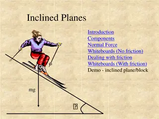
Friction clutches play a vital role in transmitting power in machines, especially those requiring frequent starting and stopping. They use friction to smoothly start driven shafts without excessive slipping. Different types of friction clutches, like disc or plate clutches, cone clutches, and centrifugal clutches, serve specific purposes in power transmission systems. Proper alignment, surface properties, and heat dissipation are crucial for efficient clutch operation. This article delves into the working principles and considerations of friction clutches in various applications.

Download Presentation

Please find below an Image/Link to download the presentation.
The content on the website is provided AS IS for your information and personal use only. It may not be sold, licensed, or shared on other websites without obtaining consent from the author.If you encounter any issues during the download, it is possible that the publisher has removed the file from their server.
You are allowed to download the files provided on this website for personal or commercial use, subject to the condition that they are used lawfully. All files are the property of their respective owners.
The content on the website is provided AS IS for your information and personal use only. It may not be sold, licensed, or shared on other websites without obtaining consent from the author.
E N D
Presentation Transcript
FIRST SEMESTER CHAPTER FOUR Friction Clutches Dr. Adil ABed Nayeeif 2019-2020
Friction Clutches A friction clutch has its principal application in the transmission of power of shafts and machines which must be started and stopped frequently. The force of friction is used to start the driven shaft from rest and gradually brings it up to the proper speed without excessive slipping of the friction surfaces. In automobiles, friction clutch is used to connect the engine to the driven shaft. In operating such a clutch, care should be taken so that the friction surfaces engage easily and gradually brings the driven shaft up to proper speed. The proper alignment of the bearing must be maintained and it should be located as close to the clutch as possible. It may be noted that. 1. The contact surfaces should develop a frictional force that may pick up and hold the load with reasonably low pressure between the contact surfaces. 2. The heat of friction should be rapidly dissipated and tendency to grab should be at a minimum. 3. The surfaces should be backed by a material stiff enough to ensure a reasonably uniform distribution of pressure. The friction clutches of the following types are important from the subject point of view : i. Disc or plate clutches (single disc or multiple disc clutch), ii. Cone clutches, and iii. Centrifugal clutches.
Single Disc or Plate Clutch A single disc or plate clutch, as shown in Figure(1), consists of a clutch plate whose both sides are faced with a friction material (usually of Ferrodo). It is mounted on the hub which is free to move axially along the splines of the driven shaft. The pressure plate is mounted inside the clutch body which is bolted to the flywheel. Both the pressure plate and the flywheel rotate with the engine crankshaft or the driving shaft. The pressure plate pushes the clutch plate towards the flywheel by a set of strong springs which are arranged radially inside the body. The three levers (also known as release levers or fingers) are carried on pivots suspended from the case of the body. The axial pressure exerted by the spring provides a frictional force in the circumferential direction when the relative motion between the driving and driven members tends to take place .If the torque due to this frictional force exceeds the torque to be transmitted, then no slipping takes place and the power is transmitted from the driving shaft to the driven shaft. Figure(1)
Now consider two friction surfaces, maintained in contact by an axial thrust W, as shown in Figure (2). T = Torque transmitted by the clutch, p = Intensity of axial pressure with which the contact surfaces are held together, r1 and r2 = External and internal radii of friction faces, and = Coefficient of friction. Consider an elementary ring of radius r and thickness dr as shown in Figure (2) We know that area of contact surface or friction surface, = 2 r.dr Normal or axial force on the ring, or axial force on the ring, W = Pressure Area = p 2 r.dr and the frictional force on the ring acting tangentially at radius r, Fr = . W = .p 2 r.dr Frictional torque acting on the ring, Tr = Fr r = .p 2 r.dr r = 2 .p.r2 dr We shall now consider the following two cases : 1. When there is a uniform pressure, and 2. When there is a uniform wear. Figure (2)
Considering uniform pressure When the pressure is uniformly distributed over the entire area of the friction face, then the intensity of pressure, W P (1) ( 1 r = ) r 2 2 2 where : W = Axial thrust with which the contact or friction surfaces are held together. We have discussed above that the frictional torque on the elementary ring of radius r and thickness dr is Tr = 2 .p.r2 dr Integrating this equation within the limits from r2 to r1 for the total frictional torque . Total frictional torque acting on the friction surface or on the clutch, = 3 2 r r 3 r r r 3 3 3 1 r 1 = = T P r dr . P P . . . . 2 2 2 2 1 2 r 2 Substituting the value of p from equation (1), r r 2 3 3 3 W r r 3 3 = 3 = T W WR 1 2 = T 2 1 2 ( ) r r 2 2 r r 2 2 1 2 1 2 r r 2 3 3 = where R = Mean radius of friction surface, R 1 2 r r 3 2 2 1 2
Considering uniform wear In Figure (2) , let pbe the normal intensity of pressure at a distance rfrom the axis of the clutch. Since the intensity of pressure varies inversely with the distance, therefore; p.r. = C (a constant) or p = C/r (1) C and the normal force on the ring, = 2 = 2 = 2 W P r dr . r dr . C dr . . r Total force acting on the friction surface, r = = . W = C r ( ) 1 ( ) = 2 r W C dr C C r r 2 2 2 1 r r r 1 2 2 1 2 r C 2 We know that the frictional torque acting on the ring, = = Tr P r dr . r dr . . . 2 2 2 2 r Total frictional torque on the friction surface, r 2 r r r 2 2 2 1 r 1 = = = T C . r dr . C . C . . 2 2 2 1 2 2 r r 2 2 W ( ) ( ) = . = T C r r r r 2 2 2 2 ( ) 2 r r 1 2 1 2 1 2 1 ( ) = 2 + = T W . r r WR 1 2 1 ( ) = + R r r R = Mean radius of the friction surface, 1 2 2
Multiple Disc Clutch A multiple disc clutch, as shown in Figure (3) , may be used when a large torque is to be transmitted. The inside discs (usually of steel) are fastened to the driven shaft to permit axial motion (except for the last disc). The outside discs (usually of bronze) are held by bolts and are fastened to the housing which is keyed to the driving shaft. The multiple disc clutches are extensively used in motor cars, machine tools etc. Let n1= Number of discs on the driving shaft, and n2= Number of discs on the driven shaft. Number of pairs of contact surfaces, n = n1 + n2 1 and total frictional torque acting on the friction surfaces or on the clutch, T = n. .W.R where R = Mean radius of the friction surfaces, 2 1 3 r r r r 2 3 3 (For uniform pressure ) = R 1 2 2 2 Figure (3) 1 (For uniform wear ) ( ) 2 1 2 = + R r r
Cone Clutch A cone clutch, as shown in Figure (4) , was extensively used in automobiles but now-a-days it has been replaced completely by the disc clutch. It consists of one pair of friction surface only. In a cone clutch, the driver is keyed to the driving shaft by a sunk key and has an inside conical surface or face which exactly fits into the outside conical surface of the driven. Due to the frictional resistance set up at this contact surface, the torque is transmitted from one shaft to another In some cases, a spring is placed around the driven shaft in contact with the hub of the driven. Figure (4)
Consider a pair of friction surface as shown in Figure (5). Since the area of contact of a pair of friction surface is a frustrum of a cone, therefore the torque transmitted by the cone clutch may be determined in the similar manner as discussed for conical pivot bearings. pn= Intensity of pressure with which the conical friction surfaces are held together (i.e. normal pressure between contact surfaces), r1 and r2 = Outer and inner radius of friction surfaces respectively. 1 ( ) = + R r r R = Mean radius of the friction surface, 1 2 2 = Semi angle of the cone (also called face angle of the cone) or the angle of the friction surface with the axis of the clutch, = Coefficient of friction between contact surfaces, and b = Width of the contact surfaces (also known as face width or clutch face). Figure (5)
Consider a small ring of radius rand thickness dr, as shown in Figure (5). Let dlis length of ring of the friction surface, such that dl = dr.cosec Area of the ring, A = 2 r.dl = 2 r.dr cosec We shall consider the following two cases : 1. When there is a uniform pressure, and 2. When there is a uniform wear. Considering uniform pressure We know that normal load acting on the ring, Wn = Normal pressure Area of ring = pn 2 r.dr.cosec and the axial load acting on the ring, W= Horizontal component of Wn(i.e. in the direction of W) = Wn sin = pn 2 r.dr. cosec sin = 2 pn.r.dr Total axial load transmitted to the clutch or the axial spring force required, 2 2 r W pn r 2 r r r 2 2 2 1 r ( ) 1 = = 2 . = 2 = 2 W P r r W P rdr P P 2 2 1 2 n n n n 1 2 r 2 = ..(1) ( 1 r ) r 2 2 2
We know that frictional force on the ring acting tangentially at radius r, Fr = . Wn = .pn 2 r.dr.cosec Frictional torque acting on the ring, Tr = Fr r = .pn 2 r.dr. cosec .r = 2 .pn .cosec .r2 dr Integrating this expression within the limits from r2 to r1 for the total frictional torque on the clutch. Total frictional torque, r 3 r r r 3 3 3 1 r 1 = = = T P ec r dr . P ec P ec . . cos . cos . cos 2 2 2 2 1 2 n n n 3 r r 2 2 3 W r r 3 3 = Substituting the value of pn from equation (1), we get T ec cos 2 1 2 ( ) r r 2 2 1 2 r r 2 3 3 = T W ec cos 1 2 r r 3 2 2 1 2 Considering uniform wear In Figure (5), let pr be the normal intensity of pressure at a distance r from the axis of the clutch. We know that, in case of uniform wear, the intensity of pressure varies inversely with the distance. p.r. = C (a constant) or p = C/r We know that the normal load acting on the ring, Wn = Normal pressure Area of ring = pr 2 r.dr cosec
and the axial load acting on the ring , W = Wn sin = pr .2 r.dr.cosec .sin = pr 2 r.dr C = 2 = 2 W r dr . C dr . r r r Total axial load transmitted to the clutch, ( ) 1 = 2 . = 2 = 2 r W C dr C C r r 1 r 1 2 2 r W 2 = C ( ) 2 r r 1 2 We know that frictional force acting on the ring, Fr = . Wn = .pr 2 r dr cosec and frictional torque acting on the ring, Tr = Fr r = .pr 2 r.dr.cosec r C = 2 = 2 Tr r dr . ec C . rdr ec . . cos cos 2 r Total frictional torque acting on the clutch, r 2 r r r 2 2 2 1 r 1 = = = T C . r dr . ec P ec P ec . cos . cos . cos 2 2 2 1 2 2 r Substituting the value of C from equation (1), we have W T 1 r 2 2 2 r r 2 2 = ec cos 2 1 2 ( ) ( r r 2 1 2 ) = 2 + = ec T W . ec r r WR cos cos 1 2
1 Where mean radius of friction surface ( ) 2 1 2 = + R r r The forces on a friction surface, for steady operation of the clutch and after the clutch is engaged, is shown in Figure (6) r r R and b r r 2 2 W r r r r r r 2 2 1 2 1 2 1 + + = sin = + = or r r R , 1 2 2 1 1 2 W W = = = Pn ( ) ( )( ) R b sin 2 2 W = pn 2 R.b sin = Wn sin Wn = Normal load acting on the friction surface = pn 2 R.b T = (pn Rb sin ) R cosec = pnR2b Axial force required for engaging the clutch, We = W + .Wn cos = Wn sin + .Wn cos = Wn(sin + cos ) Wd = Wn ( cos sin ) Wd : the axial force required to disengage the clutch Figure (6)
Centrifugal Clutch The centrifugal clutches are usually incorporated into the motor pulleys. It consists of a number of shoes on the inside of a rim of the pulley, as shown in Figure(7). The outer surface of the shoes are covered with a friction material. These shoes, which can move radially in guides, are held against the boss (or spider) on the driving shaft by means of springs. The force with which the shoe presses against the driven member is the difference of the centrifugal force and the spring force. The increase of speed causes the shoe to press harder and enables more torque to be transmitted. In order to determine the mass and size of the shoes, the following procedure is adopted : Figure(7)
Mass of the shoes Consider one shoe of a centrifugal clutch as shown in Figure (8) m = Mass of each shoe, n = Number of shoes, r = Distance of centre of gravity of the shoe from the centre of the spider, R = Inside radius of the pulley rim, N = Running speed of the pulley in r.p.m., = Angular running speed of the pulley in rad/s= 2 N/60 rad/s, Figure (8) 1 = Angular speed at which the engagement begins to take place and , = Coefficient of friction between the shoe and rim. We know that the centrifugal force acting on each shoe at the running speed, Pc = m. 2 .r and the inward force on each shoe exerted by the spring at the speed at which engagement begins to take place, Ps = m ( 1 )2r. The net outward radial force (i.e. centrifugal force) with which the shoe presses against the rim at the running speed = Pc Ps
and the frictional force acting tangentially on each shoe,F = (Pc Ps ) Frictional torque acting on each shoe, = F R = (Pc Ps) R. and total frictional torque transmitted, T = (Pc Ps) R n = n.F.R From this expression, the mass of the shoes (m) may be evaluated Size of the shoes l = Contact length of the shoes, b = Width of the shoes R = Contact radius of the shoes. It is same as the inside radius of the rim of the pulley. = Angle subtended by the shoes at the centre of the spider in radians. p = Intensity of pressure exerted on the shoe. In order to ensure reasonable life, the intensity of pressure may be taken as 0.1 N/mm2. We know that = l/R rad or l = .R Area of contact of the shoe, A = l.b and the force with which the shoe presses against the rim, = A p = l.b.p Since the force with which the shoe presses against the rim at the running speed is (Pc Ps), therefore l.b.p = Pc P From this expression, the width of shoe (b) may be obtained.
Examples Ex(1) A single plate clutch, effective on both sides, is required to transmit 25 kW at 3000 r.p.m. Determine the outer and inner radii of frictional surface if the coefficient of friction is 0.255, the ratio of radii is 1.25 and the maximum pressure is not to exceed 0.1 N/mm2. Also determine the axial thrust to be provided by springs. Assume the theory of uniform wear. Solution. Given: n = 2 ; P = 25 kW = 25 103 W ; N = 3000 r.p.m. or = 2 3000/60 = 314.2 rad/s ; = 0.255 ; r1/r2= 1.25 ; p = 0.1 N/mm2 Outer and inner radii of frictional surface r1 and r2 = Outer and inner radii of frictional surfaces, and T = Torque transmitted Since the ratio of radii (r1 /r2) is 1.25, therefore r1 = 1.25 r2 We know that the power transmitted (P),25 103 = T. = T 314.2 T = 25 103/314.2 = 79.6 N-m = 79.6 103 N-mm Since the intensity of pressure is maximum at the inner radius (r2), therefore p.r2 = C or C = 0.1 r2N/mm and the axial thrust transmitted to the frictional surface, W = 2 C (r1 r2) = 2 0.1 r2(1.25 r2 r2) = 0.157 (r2 )2 ..(1) + + r r r r . 1 25 We know that mean radius of the frictional surface for uniform wear, = = = R r . 1 125 1 2 2 2 2 2 2
We know that torque transmitted (T), 79.6 103 = n. .W.R = 2 0.255 0.157 (r2)2 1.125 r2= 0.09 (r2)3 (r2)3= 79.6 103/0.09 = 884 103 or r2= 96 mm Ans. r1= 1.25 r2= 1.25 96 = 120 mm Ans. Axial thrust to be provided by springs We know that axial thrust to be provided by springs, W = 2 C (r1 r2) = 0.157 (r2)2 = 0.157 (96)2 = 1447 N Ans.
Ex(2) : A plate clutch has three discs on the driving shaft and two discs on the driven shaft, providing four pairs of contact surfaces. The outside diameter of the contact surfaces is 240 mm and inside diameter 120 mm. Assuming uniform pressure and = 0.3; find the total spring load pressing the plates together to transmit 25 kW at 1575 r.p.m. If there are 6 springs each of stiffness 13 kN/m and each of the contact surfaces has worn away by 1.25 mm, find the maximum power that can be transmitted, assuming uniform wear. Solution. Given : n1= 3 ; n2= 2 ; n = 4 ; d1 = 240 mm or r1 = 120 mm ; d2 = 120 mm or r2= 60 mm ; = 0.3 ; P = 25 kW = 25 103 W ; N = 1575 r.p.m. or = 2 1575/60 = 165 rad/s Total spring load W = Total spring load, and T = Torque transmitted We know that power transmitted (P), 25 103 = T. = T 165 or T = 25 103/165 = 151.5 N-m ( ( ) ) ( ) ( ) 60 3 3 r r 2 2 120 60 3 3 = = = = Mean radius of the contact surface, for uniform pressure, R mm m 3 . 0933 . 93 0 1 2 2 2 r r 3 3 120 2 2 1 2 and torque transmitted (T ), 151.5 = n. .W.R = 4 0.3 W 0.0933 = 0.112 W W = 151.5/0.112 = 1353 N Ans.
Maximum power transmitted Given : No of springs = 6 Contact surfaces of the spring = 8 Wear on each contact surface = 1.25 mm Total wear = 8 1.25 = 10 mm = 0.01 m Stiffness of each spring = 13 kN/m = 13 103 N/m Reduction/ in spring force = Total wear Stiffness per spring No. of springs = 0.01 13 103 6 = 780 N New axial load, W = 1353 780 = 573 N We know that mean radius of the contact surfaces for uniform wear, + + r r 120 60 = = = = R mm m . 90 0 09 1 2 2 2 Torque transmitted, T = n. .W.R. = 4 0.3 573 0.09 = 62 N-m and maximum power transmitted, P= T. = 62 155 = 10 230 W = 10.23 kWAns.
Ex(3) : An engine developing 45 kW at 1000 r.p.m. is fitted with a cone clutch builtinside the flywheel. The cone has a face angle of 12.5 and a maximum mean diameter of 500 mm The coefficient of friction is 0.2. The normal pressure on the clutch face is not to exceed 0.1 N/mm2Determine : 1. the axial spring force necessary to engage to clutch, and 2. the face width required Solution. Given : P = 45 kW = 45 103 W ; N = 1000 r.p.m. Or = 2 1000/60 = 104.7 rad/s ; = 12.5 ; D = 500 mm or R = 250 mm = 0.25 m ; = 0.2 ; pn= 0.1 N/mm2 Axial spring force necessary to engage the clutch First of all, let us find the torque (T ) developed by the clutch and the normal load (Wn) acting on the friction surface. We know that power developed by the clutch (P), 45 103 = T. = T 104.7 or T = 45 103/104.7 = 430 N-m We also know that the torque developed by the clutch (T), 430 = .Wn .R = 0.2 Wn 0.25 = 0.05 Wn Wn = 430/0.05 = 8600 N and axial spring force necessary to engage the clutch, We = Wn (sin + cos ) = 8600 (sin 12.5 + 0.2 cos 12.5 ) = 3540 N Ans.
Face width required b= Face width required We know that normal load acting on the friction surface (Wn), 8600 = pn 2 R.b = 0.1 2 250 b = 157 b b = 8600/157 = 54.7 mm Ans.
Ex(4) : A centrifugal clutch is to transmit 15 kW at 900 r.p.m. The shoes are four in number. The speed at which the engagement begins is 3/4th of the running speed. The inside radius of the pulley rim is 150 mm and the centre of gravity of the shoe lies at 120 mm from the centre of the spider. The shoes are lined with Ferrodo for which the coefficient of friction may be taken as 0.25. Determine : 1. Mass of the shoes, and 2. Size of the shoes, if angle subtended by the shoes at the centre of the spider is 60 and the pressure exerted on the shoes is 0.1 N/mm2 Solution. Given: P = 15 kW = 15 103 W ; N = 900 r.p.m. or = 25 900/60 = 94.26 rad/s ; n = 4 ; R = 150 mm = 0.15 m ; r = 120 mm = 0.12 m ; = 0.25 Since the speed at which the engagement begins (i.e. 1) is 3/4th of the running speed (i.e. ), therefore; rad/sec . . 7 70 26 94 4 4 3 3 = = = 1 T = Torque transmitted at the running speed. We know that power transmitted (P), 15 103 = T. = T 94.26 or T = 15 103/94.26 = 159 N-m Mass of the shoes m = Mass of the shoes in kg. We know that the centrifugal force acting on each shoe, Pc = m. 2.r = m (94.26)2 0.12 = 1066 m N and the inward force on each shoe exerted by the spring i.e. the centrifugal force at the engagement speed 1 Ps= m ( 1)2r = m (70.7)2 0.12 = 600 m N Frictional force acting tangentially on each shoe, F = (Pc Ps) = 0.25 (1066 m 600 m) = 116.5 m N
We know that the torque transmitted (T), 159 = n.F.R = 4 116.5 m 0.15 = 70 m or m = 2.27 kg Ans. Size of the shoes l = Contact length of shoes in mm, b = Width of the shoes in mm, = Angle subtended by the shoes at the centre of the spider in radians = 60 = /3 rad, and p = Pressure exerted on the shoes in N/mm2 = 0.1 N/mm2 = = = We know that, l R mm . 1 . 150 157 3 l.b.p = Pc Ps = 1066 m 600 m = 466 m 157.1 b 0.1 = 466 2.27 = 1058 b = 1058/157.1 0.1 = 67.3 mm Ans.
Exercises Q1/A plate clutch having a single driving plate with contact surfaces on each side is required to transmit 110 kW at 1250 r.p.m. The outer diameter of the contact surfaces is to be 300 mm. The coefficient of friction is 0.4. (a) Assuming a uniform pressure of 0.17 N/mm2; determine the inner diameter of the friction surfaces. (b) Assuming the same dimensions and the same total axial thrust, determine the maximum torque that can be transmitted and the maximum intensity of pressure when uniform wear conditions have been reach. Q2/ A dry single plate clutch is to be designed for an automotive vehicle whose engine is rated to give 100 kW at 2400 r.p.m. and maximum torque 500 N-m. The outer radius of the friction plate is 25% more than the inner radius. The intensity of pressure between the plate is not to exceed 0.07 N/mm2. The coefficient of friction may be assumed equal to 0.3. The helical springs required by this clutch to provide axial force necessary to engage the clutch are eight. If each spring has stiffness equal to 40 N/mm, determine the dimensions of the friction plate and initial compression in the springs
Q3/ A multiple disc clutch, steel on bronze, is to transmit 4.5 kW at 750 r.p.m. The inner radius of the contact is 40 mm and outer radius of the contact is 70 mm. The clutch operates in oil with an expected coefficient of 0.1. The average allowable pressure is 0.35 N/mm2. Find: 1. the total number of steel and bronze discs; 2. the actual axial force required; 3. the actual average pressure; and 4. the actual maximum pressure. Q4/ The contact surfaces in a cone clutch have an effective diameter of 80 mm. The semi-angle of the cone is 15 and coefficient of friction is 0.3. Find the torque required to produce slipping of the clutch, if the axial force applied is 200 N. The clutch is employed to connect an electric motor, running uniformly at 900 r.p.m. with a flywheel which is initially stationary. The flywheel has a mass of 14 kg and its radius of gyration is 160 mm. Calculate the time required for the flywheel to attain full-speed and also the energy lost in slipping of the clutch.


.")


,")
 : A plate clutch has three discs on the driving shaft")

 : An engine developing 45 kW at 1000 r.p.m. is fitted")

 : A centrifugal clutch is to transmit 15 kW at 900")
,")