Flash Array Storage Infrastructure and SSD Performance
The article discusses alleviating garbage collection interference in flash arrays and the importance of spatial separation. It also covers the concept of All Flash Arrays (AFA) and provides examples of AFA products and SSDs for enterprise use. Furthermore, it explores bandwidth trends for network and storage interfaces in the industry.

Download Presentation

Please find below an Image/Link to download the presentation.
The content on the website is provided AS IS for your information and personal use only. It may not be sold, licensed, or shared on other websites without obtaining consent from the author.If you encounter any issues during the download, it is possible that the publisher has removed the file from their server.
You are allowed to download the files provided on this website for personal or commercial use, subject to the condition that they are used lawfully. All files are the property of their respective owners.
The content on the website is provided AS IS for your information and personal use only. It may not be sold, licensed, or shared on other websites without obtaining consent from the author.
E N D
Presentation Transcript
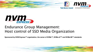
Alleviating Garbage Collection Interference through Spatial Separation in All Flash Arrays Jaeho Kim, Kwanghyun Lim*, Youngdon Jung, Sungjin Lee, Changwoo Min, Sam H. Noh 1 *Currently with Cornell Univ.
All Flash Array (AFA) Storage infrastructure that contains only flash memory drives Also called Solid-State Array (SSA) https://images.google.com/ https://www.purestorage.com/resources/glossary/all-flash-array.html 2
Example of All Flash Array Products (1 brick or node) EMC XtremIO HPE 3PAR SKHynix AFA Capacity 36 ~ 144 TB 750 TB 552 TB Number of SSDs 18 ~ 72 120 576 Network Ports 4~8 x 10Gb iSCSI 4~12 x 16Gb FC 3 x Gen3 PCIe Aggregate Network Throughput 5 ~ 10 GB/s 8 ~ 24 GB/s 48 GB/s A: EMC XtremIO X2 Specification B: HPE 3PAR StoreServ Specification C: Performance Analysis of NVMe SSD-Based All-flash Array Systems. [ISPASS 18] 3 https://www.flaticon.com/
SSDs for Enterprise Manufacturer Product Name Seq. Read Throughput Seq. Write Throughput Capacity DC P4800X 2.5 GB/s 2.2 GB/s 1.5 TB DC D3700 2.1 GB/s 1.5 GB/s 1.6 TB Intel DC P3608 5 GB/s 3 GB/s 4 TB PM1725b 6.3 GB/s 3.3 GB/s 12.8 TB Samsung PM983 3.2 GB/s 2 GB/s 3.8 TB Intel: https://www.intel.com/content/www/us/en/products/memory-storage/solid-state-drives/data-center-ssds.html Samsung: https://www.samsung.com/semiconductor/ssd/enterprise-ssd/ 4
Bandwidth Trends for Network and Storage Interfaces 80 Infiniband Storage Interface 70 PCIe 5 Network Interface 60 Storage throughput increases quickly Storage isn t bottleneck anymore 400GbE 50 Bandwidth (GB/s) Infiniband 40 PCIe 4 30 200GbE Infiniband 20 100GbE PCI-3 10 40GbE SAS-4 SAS-3SATA Exp. 10GbE SATA3 SATA2 0 SAS-2 Year Interfaces: https://en.wikipedia.org/wiki/List_of_interface_bit_rates#Local_area_networks SATA: https://en.wikipedia.org/wiki/Serial_ATA PCIe: https://en.wikipedia.org/wiki/PCI_Express 5
Example of All Flash Array Products (1 brick or node) EMC XtremIO HPE 3PAR SKHynix AFA Capacity Throughput of a few high-end SSDs can easily saturate the network throughput 36 ~ 144 TB 750 TB 552 TB Number of SSDs 18 ~ 72 120 576 Network Ports 4~8 x 10Gb iSCSI 4~12 x 16Gb FC 3 x Gen3 PCIe Aggregate Network Throughput 5 ~ 10 GB/s 8 ~ 24 GB/s 48 GB/s A: EMC XtremIO X2 Specification B: HPE 3PAR StoreServ Specification C: Performance Analysis of NVMe SSD-Based All-flash Array Systems. [ISPASS 18] 6
Current Trends and Challenges Performance of SSDs is fairly high Throughput of a few SSDs easily saturates network bandwidth of a AFA node Trends Garbage Collection (GC) of SSD is still performance bottleneck in AFA What is an ideal way to manage an array of SSDs with the current trends? Challenges 7
Traditional RAID Approaches Traditional RAID employs in-place update for serving write requests High GC overhead inside SSD due to random write from the host APP Random writes OS RAID 4/5 In-place write Limitations Previous solutions 1)Harmonia [MSST 11] 2)HPDA [TOS 12] 3)GC-Steering [IPDPS 18] Random writes AFA GC SSD SSD SSD SSD 8
Log-(based) RAID Approaches Log-based RAID employs log-structured writes to reduce GC overhead inside SSD Log-structured writes involve host-level GC, which relies on idle time If no idle time, GC will cause performance drop APP Random writes OS Log-RAID Log-structured write GC Sequential writes AFA Limitations Previous solutions 1)SOFA [SYSTOR 14] 2)SRC [Middleware 15] 3)SALSA [MASCOTS 18] SSD SSD SSD SSD 9
Performance of a Log-based RAID Configuration Consist of 8 SSDs (roughly 1TB capacity) Workload Random write requests continuously for 2 hours GC starts here How can we avoid this performance variation due to GC in All Flash Array? Interference between GC I/O and user I/O 10
Our Solution (SWAN) SWAN (Spatial separation Within an Array of SSDs on a Network) Goals Provide sustainable performance up to network bandwidth of AFA Alleviate GC interference between user I/O and GC I/O Find an efficient way to manage an array of SSDs in AFA Approach Minimize GC interference throughSPATIAL separation 11 Image: https://clipartix.com/swan-clipart-image-44906/
Our Solution: Brief Architecture of SWAN APP Divide an array of SSDs into front-end and back-end like 2-D array Called, SPATIAL separation Employ log-structured writes GC effect is minimized by spatial separation between GC and user I/O Random writes Log-based RAID: Temporal separation between GC and user I/O SWAN: OS SWAN Spatial separation Log-structured write Spatial Separation Reduced VS. Append-only manner GC effect AFA SSD SSD SSD SSD SSD SSD Back-end Front-end 12
Architecture of SWAN Spatial separation Front-end: serve all write requests Back-end: perform SWAN s GC Log-structured write Segment based append only writes, which is flash friendly Mapping table: 4KB granularity mapping table Implemented in block I/O layer where I/O requests are redirected from the host to the storage 13
Example of Handling I/O in SWAN W R SSD Read req. Write req. W3 R8 W1 R7 Block I/O Interface Logical Volume W1 W1 W3 W3 R7 R7 R8 R8 Physical Volume Logging W1 Segment W3 W3 W1 Front-end Back-end Back-end SSD R7 W1 like RAID parallelism W3 R8 SSD SSD Parity 14
Procedure of I/O Handling (1/3) W P Write Parity Front-end absorbs all write requests in append-only manner To exploit full performance of SSDs Write Req. Front-end Back-end Back-end SSD SSD W parallelism unit Segment SSD SSD W P SSD SSD Append only (a) First - phase 15
Procedure of I/O Handling (2/3) W P Write Parity When the front-end becomes full Empty back-end becomes front-end to serve write requests Full front-end becomes back-end Again, new front-end serves write requests Write Req. Front-end becomes full Front-end Back-end Back-end Back-end Front-end SSD SSD W Segment Segment Segment SSD SSD W P SSD SSD (a) Second - phase 16
Procedure of I/O Handling (3/3) When there is no more empty back-end SWAN s GC is triggered to make free space SWAN chooses a victim segment from one of the back-ends SWAN writes valid blocks within the chosen back-end Finally, the victim segment is trimmed W P GC TRIM Write Parity Write Req. SWAN GC Back-end All write requests and GC are spatially separated Front-end Back-end Ensure writing a segment sequentially inside SSDs SSD SSD Segment W W Segment Segment Segment P Segment Segment W SSD SSD W P SSD SSD TRIMmed (a) Third - phase 17
Feasibility Analysis of SWAN Analytic model of SWAN GC How many back-ends in AFA ? SWAN GC How many SSDs in front-end? SSD SSD SSD SSD SSD SSD Back-end Front-end Back-end Please refer to our paper for details! 18
Evaluation Setup Environment Dell R730 server with Xeon CPUs and 64GB DRAM Up to 9 SATA SSDs are used (up to 1TB capacity) Open channel SSD for monitoring internal activity of an SSD Target Configurations RAID0/4: Traditional RAID Log-RAID0/4: Log-based RAID SWAN0/4: Our solution Workloads Micro-benchmark: Random write request YCSB C benchmark No parity RAID0 Log-RAID0 SWAN0 1 parity per stripe RAID4 Log-RAID4 SWAN4 Please refer to paper for more results! 19
Random Write Requests for 2 Hours (8KB Sized Req.) GC starts here GC starts here Interference between GC I/O and user I/O Log-RAID0 SWAN0 20
Write throughput Analysis of Log-RAID s Write Performance GC starts here: All SSDs involved in GC Read throughput SSD1 SSD 1 SSD2 SSD 2 Red lines increases while blue lines drop down since GC incurs read and write operations GC starts here SSD3 SSD 3 Throughput (MB/sec) SSD4 SSD 4 SSD5 SSD 5 SSD6 SSD 6 Performance fluctuates as all SSDs are involved in GC SSD7 SSD 7 Log-RAID0 SSD8 SSD 8 a User observed throughput USER 600 1200 1800 2400 3000 3600 21 Time (sec)
Analysis of SWANs Write Performance GC starts here Only one back-end is involved in GC Front-end Write throughput Read throughput Back-end SSD1 SSD 1 GC starts here c SSD2 SSD 2 Front-end SSD3 SSD 3 Throughput (MB/sec) This pattern continues SWAN separates write requests and GC SSD4 SSD 4 Front-end SSD5 SSD 5 SSD6 SSD 6 Front-end Configuration SSD7 SSD 7 SWAN has 1 front-end and 4 back-ends Front/back-ends consists of 2 SSDs b SSD8 SSD 8 User observed throughput USER 600 1200 1800 2400 3000 3600 Time (sec) 22
Read Tail Latency for YCSB-C SWAN4 shows the shortest read tail latency RAID4 and Log-RAID4 suffers long tail latency SWAN4 RAID4 Log-RAID4 1 Spatial separation is effective for handling read requests as well 0.999 1 0.9999 0.998 0.9998 0.9997 0.997 0.9996 0.9995 0.996 0 100 200 300 400 500 600 0.995 0 200 400 600 800 1000 Time (msec) 23
Benefits with Simpler SSDs SWAN can saves cost and power consumption w/o compromising performance by adopting simpler SSDs 1) Smaller DRAM size 2) Smaller over-provisioning space (OPS) 3) Block or segment level FTL instead of page-level FTL SWAN sequentially writes data to segments and TRIMs a large chunk of data in the same segment at once 24
Conclusion Provide full write performance of an array of SSDs up to network bandwidth limit Alleviate GC interference through separation of I/O induced by application and GC of All Flash Array Introduce an efficient way to manage SSDs in All Flash Array Thanks for attention! Q&A 25
Handling Read Requests in SWAN Recent updated data might be served at page cache or buffer Falling in front-end Give a highest priority to read requests Falling in GC back-end Preempt GC then serve read requests Falling in idle back-ends Server immediately read requests 27
GC overhead inside SSDs GC overhead should be very low inside SSDs because We write all the data in a segment-based append-only manner Then give TRIMs to ensure writing a segment sequentially inside SSDs 28
Previous Solutions Solutions Write Strategy How Separate User & GC I/O Disk Organization Harmonia [MSST 11] In-place write Temporal (Idle time) RAID-0 HPDA [IPDPS 10] In-place write Temporal RAID-4 GC-Steering [IPDPS 18] In-place write Temporal RAID-4/5 SOFA [SYSTOR 14] Log write Temporal Log-RAID SALSA [MASCOTS 18] Log write Temporal Log-RAID Purity [SIGMOD 15] Log write Temporal Log-RAID SWAN (Proposed) Log write Spatial 2D Array 29

")


 RAID Approaches")

")


")
")
")


")