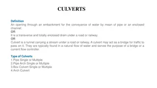
Enhanced Specifications for Pipe Culverts and Drainage Structures
Supplemental Specification 802:
Constructing and Inspecting
Pipe Culverts, Sewers, Drains
and Drainage Structures
Ted Strickland, Governor
Jolene Molitoris, ODOT Director
John Stains, P.E.
Roadway Hydraulics Engineer
Central Office, Hydraulics Section
Performance vs. Method Specs
ODOT has historically used Method
Specs
603/604 details excavation, bedding
and backfill materials and methods of
compaction
SS 802 allows the contractor to
determine means and methods
Other ODOT Performance
Based Specifications
SS 832: Temporary Sediment and
Erosion Control
441: Contractor Mix Design and
Quality Control- Asphalt Concrete
SS 802 Development
Originally introduced in 2005
Optional on all projects, required on
one trial project
Rewritten in 2008
Collaboration between Hydraulics,
Construction Administration, OCA
and Pipe Manufacturers
Implemented in Pilot Program 2009
Purpose of SS 802
Take advantage of efficiencies in
time and cost by allowing the
contractor to choose method of
installation
Encourage innovative and creative
construction techniques
Allow for new pipe materials to be
introduced
Goals
Fully implement SS 802 on all
projects by the end of 2010
Integrate inspection data into culvert
inventory
Elements of SS 802
Develop installation plan
Construct pipe and drainage
structures according to installation
plan
Inspect pipe and drainage structures
30 days after construction
Repair any defects at no additional
cost to Department
Approved Materials
Conduit material specifically detailed
in the plans or listed in the
specification by installation type
Drainage structure materials listed in
the specification
Bedding and backfill material listed in
the specification
All other materials as listed in the
specification
Installation Plan
Trench and excavation geometry
Identify all cut and fill installations
Identify bedding and backfill material
Identify lift thickness, compaction
equipment and compaction density
Conduit type, size and type of
drainage structures
Maximum joint gap
Other details as needed
Installation Plan
Provide written confirmation from the
conduit manufacturer that the pipe
material and strength supplied are
appropriate for bedding and backfill
material and density
All deviations during construction
require the installation plan to be
revised
Installation Plan Deviations
Deviations during construction
require a revision to the installation
plan to be submitted, with
manufacturer confirmation
Revisions required to be submitted
within 5 days
If revision does not receive
confirmation, all installation will be
replaced
Construction Inspection
Construction inspection forms for
conduit and drainage structures
certified and submitted by a
representative of the Contractor to
the Engineer
Deviations from installation plan are
identified
ODOT inspector role to ensure
installation plan is being followed
Post Construction Inspection
Perform inspection no sooner than
30 days after the completion of
finished grade
Inspect all structures and entire
length of all conduit
May be performed before paving
Perform remote or manual inspection
of all conduit
Post Construction Inspection
Manual Inspection
Provide a video recording of the
entire run of conduit
Measure the deflection of flexible
conduit
–
Take three measurements in each
segment
–
Report smallest diameter of each
segment of the run
Manual Inspection
Measure crack width of rigid conduit
–
Record location, length and greatest
width of each crack
Measure joint gap of all conduit
–
Record widest gap in each joint
Measure greatest width of separation
of manufactured seams
Remote Inspection
Use crawler mounted camera to
record video of all conduit
Make measurements using
equipment described in SS 902 for
conduit materials as follows:
Remote Inspection
*crack and defect measuring tool only
*crack and defect measuring tool only
Crawler Mounted Camera
Equipment requirements in
SS 902.01
Crawler with adjustable camera
height, all wheel drive, adjustable
speed
Camera with zoom, pan and tilt, light
source
Digital video
Crawler Mounted Camera
Crawler Mounted Camera with
Laser Profiler
Equipment requirements in
SS 902.02
Crawler/camera same as SS 902.01
Continuous laser ring “Scanner 3-D”
laser profiler
Deflection calculated from actual
interior circumference, not manually
input
Crawler Mounted Camera with
Laser Profiler
Calibration per ASTM E691 and E177
Automatic measurement and
recording, unable to manually input
or edit data
Crack and Defect measuring tool
accurate to 1/32”
On screen calibration at each
measurement
Crawler Mounted Camera with Laser Profiler
Control Station for Crawler and Laser Profiler
Laser Profiler Reporting
Conduit Repairs
Evaluate defects as required by
AASHTO LRFD Bridge Construction
Specifications
Evaluation performed by an
independent, third party P.E.
Conduit Repairs
If no repairs are necessary or
required, submit following statement
in the evaluation:
“I certify that repairs are not required for
the conduit to function as designed and
that the conduit meets the design life
requirements described in the version of
the Department’s
Location and Design
Manual, Volume 2, Drainage Design
, used
in the original design.”
Conduit Repairs
If repairs are necessary or required
prepare a plan for repair with
following statement:
“I certify that this repair plan was
designed to ensure the repaired conduit
will function as designed and will meet the
requirements described in the version of
the Department’s
Location and Design
Manual, Volume 2, Drainage Design
, used
in the original design.”
Conduit Repairs
Repair plans require written
confirmation from the conduit
manufacturer that repairs are
appropriate
30 days after repairs are completed,
inspect for effectiveness
Conduit repairs and additional
inspections done at no additional
cost to the Department
Conduit Repairs – Metal
Evaluate if infiltration is observed
Evaluate all racking or denting
Repair all damage to coatings
Evaluate if deflection > 5%
Repair or replace conduit if deflection
>7.5%
Conduit Repairs - Rigid
Evaluate if infiltration is observed
Evaluate if cracks > 0.01 inch
Repair or replace conduit if cracks
>0.10 inch
Repair or replace conduit if spalls or
slabbing are observed
Conduit Repairs - Plastic
Evaluate if infiltration is observed
Evaluate if deflection > 5%
Repair or replace conduit deflection
> 7.5%
Repair Methods – Flexible Pipe
Joints
Reround
Reline
Relay
Replace
Repair Methods – Rigid Pipe
Joints
Cracks
–
Epoxy Inject
–
Reline
Relay
Replace
Relining Methods
Slip lining
–
SS 837 Construction Specification
–
SS 937 Material Specification
Resin Based Liner – SS 834
Spiral Wound Profile – SS 841
Cured in Place Pipe
–
Under development
Drainage Structure Repair
Evaluation performed by an
independent, third party P.E.
Certifications, repair plan and
inspection processes are the same as
for conduit
Repairs and additional inspections
performed at no additional cost to
the Department
Drainage Structure Repairs
Basis of Payment
Payment for all inspections included
in the contract price for the pay item
Payment for all required repairs are
included in the contract price for the
pay item
All required repairs must be
completed prior to final acceptance
Basis of Payment
60% paid after installation of conduit
or drainage structure
10% paid after performance
inspection is completed
30% paid after acceptance of the
conduit or drainage structure
Where to find SS 802
All specifications available on Division of
Construction Management Website
http://www.dot.state.oh.us/Divisions/ConstructionMgt/Pages/Propos
alNotesSupplementalSpecificationsandSupplements.aspx
Contact Information
David Riley, P.E.
David.Riley@dot.state.oh.us
614-466-2599
John Stains, P.E.
John.Stains@dot.state.oh.us
614-728-1998
Becky Humphreys, P.E.
Becky.Humphreys@dot.state.oh.us
614-387-1125
Supplemental Specification 802 introduces a modern approach to the construction and inspection of pipe culverts, sewers, drains, and drainage structures. It grants contractors the flexibility to choose installation methods, fostering innovation and efficiency while accommodating new materials. The development history, goals for implementation, and key elements of SS 802 are detailed, emphasizing the shift towards performance-based specifications in infrastructure projects.

Download Presentation

Please find below an Image/Link to download the presentation.
The content on the website is provided AS IS for your information and personal use only. It may not be sold, licensed, or shared on other websites without obtaining consent from the author. Download presentation by click this link. If you encounter any issues during the download, it is possible that the publisher has removed the file from their server.
E N D
Presentation Transcript
Supplemental Specification 802: Constructing and Inspecting Pipe Culverts, Sewers, Drains and Drainage Structures Ted Strickland, Governor Jolene Molitoris, ODOT Director John Stains, P.E. Roadway Hydraulics Engineer Central Office, Hydraulics Section
Performance vs. Method Specs ODOT has historically used Method Specs 603/604 details excavation, bedding and backfill materials and methods of compaction SS 802 allows the contractor to determine means and methods
Other ODOT Performance Based Specifications SS 832: Temporary Sediment and Erosion Control 441: Contractor Mix Design and Quality Control- Asphalt Concrete
SS 802 Development Originally introduced in 2005 Optional on all projects, required on one trial project Rewritten in 2008 Collaboration between Hydraulics, Construction Administration, OCA and Pipe Manufacturers Implemented in Pilot Program 2009
Purpose of SS 802 Take advantage of efficiencies in time and cost by allowing the contractor to choose method of installation Encourage innovative and creative construction techniques Allow for new pipe materials to be introduced
Goals Fully implement SS 802 on all projects by the end of 2010 Type A (lf) 32,829 16,463 19,908 16,656 Type B (lf) 202,226 199,352 194,880 137,484 Type C (lf) 100,207 82,596 83,295 80,466 Total (lf) 335,262 298,411 298,082 234,607 FY 2007 FY 2008 FY 2009 FY 2010 Integrate inspection data into culvert inventory
Elements of SS 802 Develop installation plan Construct pipe and drainage structures according to installation plan Inspect pipe and drainage structures 30 days after construction Repair any defects at no additional cost to Department
Approved Materials Conduit material specifically detailed in the plans or listed in the specification by installation type Drainage structure materials listed in the specification Bedding and backfill material listed in the specification All other materials as listed in the specification
Installation Plan Trench and excavation geometry Identify all cut and fill installations Identify bedding and backfill material Identify lift thickness, compaction equipment and compaction density Conduit type, size and type of drainage structures Maximum joint gap Other details as needed
Installation Plan Provide written confirmation from the conduit manufacturer that the pipe material and strength supplied are appropriate for bedding and backfill material and density All deviations during construction require the installation plan to be revised
Installation Plan Deviations Deviations during construction require a revision to the installation plan to be submitted, with manufacturer confirmation Revisions required to be submitted within 5 days If revision does not receive confirmation, all installation will be replaced
Construction Inspection Construction inspection forms for conduit and drainage structures certified and submitted by a representative of the Contractor to the Engineer Deviations from installation plan are identified ODOT inspector role to ensure installation plan is being followed
Post Construction Inspection Perform inspection no sooner than 30 days after the completion of finished grade Inspect all structures and entire length of all conduit May be performed before paving Perform remote or manual inspection of all conduit
Post Construction Inspection Manual Inspection Conduits with a rise of 48 inches and greater All Non-circular conduit Remote Inspection Conduits with a rise of 12 inches or greater up to 48 inches Conduits with a rise less than 12 inches as directed by Engineer All Drainage structures
Manual Inspection Provide a video recording of the entire run of conduit Measure the deflection of flexible conduit Take three measurements in each segment Report smallest diameter of each segment of the run
Manual Inspection Measure crack width of rigid conduit Record location, length and greatest width of each crack Measure joint gap of all conduit Record widest gap in each joint Measure greatest width of separation of manufactured seams
Remote Inspection Use crawler mounted camera to record video of all conduit Make measurements using equipment described in SS 902 for conduit materials as follows:
Remote Inspection Measurement Equipment Crawler mounted camera with laser profiler* Crawler mounted camera with laser profiler Crawler mounted camera with laser profiler Crawler mounted camera with laser profiler Mandrel Type of Measurement Conduit Material Rigid conduit and Mortar lined CMP Joint gaps Crack widths Joint gaps Crack widths Deflection Joint gaps Crack widths Deflection Joint gaps Crack widths Deflection Deflection Plastic Ductile Iron and Steel Casing pipe Bituminous Coated and Lined CMP, Spiral Rib CMP Circular CMP *crack and defect measuring tool only
Crawler Mounted Camera Equipment requirements in SS 902.01 Crawler with adjustable camera height, all wheel drive, adjustable speed Camera with zoom, pan and tilt, light source Digital video
Crawler Mounted Camera with Laser Profiler Equipment requirements in SS 902.02 Crawler/camera same as SS 902.01 Continuous laser ring Scanner 3-D laser profiler Deflection calculated from actual interior circumference, not manually input
Crawler Mounted Camera with Laser Profiler Calibration per ASTM E691 and E177 Automatic measurement and recording, unable to manually input or edit data Crack and Defect measuring tool accurate to 1/32 On screen calibration at each measurement
Conduit Repairs Evaluate defects as required by AASHTO LRFD Bridge Construction Specifications AASHTO Section Section 26 Section 27 Section 30 Material Type Metal Conduit Concrete Conduit Plastic Conduit Evaluation performed by an independent, third party P.E.
Conduit Repairs If no repairs are necessary or required, submit following statement in the evaluation: I certify that repairs are not required for the conduit to function as designed and that the conduit meets the design life requirements described in the version of the Department s Location and Design Manual, Volume 2, Drainage Design, used in the original design.
Conduit Repairs If repairs are necessary or required prepare a plan for repair with following statement: I certify that this repair plan was designed to ensure the repaired conduit will function as designed and will meet the requirements described in the version of the Department s Location and Design Manual, Volume 2, Drainage Design, used in the original design.
Conduit Repairs Repair plans require written confirmation from the conduit manufacturer that repairs are appropriate 30 days after repairs are completed, inspect for effectiveness Conduit repairs and additional inspections done at no additional cost to the Department
Conduit Repairs Metal Evaluate if infiltration is observed Evaluate all racking or denting Repair all damage to coatings Evaluate if deflection > 5% Repair or replace conduit if deflection >7.5%
Conduit Repairs - Rigid Evaluate if infiltration is observed Evaluate if cracks > 0.01 inch Repair or replace conduit if cracks >0.10 inch Repair or replace conduit if spalls or slabbing are observed
Conduit Repairs - Plastic Evaluate if infiltration is observed Evaluate if deflection > 5% Repair or replace conduit deflection > 7.5%
Repair Methods Flexible Pipe Joints Reround Reline Relay Replace
Repair Methods Rigid Pipe Joints Cracks Epoxy Inject Reline Relay Replace
Relining Methods Slip lining SS 837 Construction Specification SS 937 Material Specification Resin Based Liner SS 834 Spiral Wound Profile SS 841 Cured in Place Pipe Under development
Drainage Structure Repair Evaluation performed by an independent, third party P.E. Certifications, repair plan and inspection processes are the same as for conduit Repairs and additional inspections performed at no additional cost to the Department
Drainage Structure Repairs Defects Requiring Evaluation Infiltration between drainage structure and conduit Grate more than 0.1 from documented station/offset or elevation Invert elevation more than 1 or 5% diameter of the conduit, whichever is greater, from documented elevation Grate does not seat properly in frame Grate not placed on required slope Grate or Frame broken or cracked Steps do not line up Drainage structure does not match standard construction drawing Manhole top does not match plans
Basis of Payment Payment for all inspections included in the contract price for the pay item Payment for all required repairs are included in the contract price for the pay item All required repairs must be completed prior to final acceptance
Basis of Payment 60% paid after installation of conduit or drainage structure 10% paid after performance inspection is completed 30% paid after acceptance of the conduit or drainage structure
Where to find SS 802 All specifications available on Division of Construction Management Website http://www.dot.state.oh.us/Divisions/ConstructionMgt/Pages/Propos alNotesSupplementalSpecificationsandSupplements.aspx
Contact Information David Riley, P.E. David.Riley@dot.state.oh.us 614-466-2599 John Stains, P.E. John.Stains@dot.state.oh.us 614-728-1998 Becky Humphreys, P.E. Becky.Humphreys@dot.state.oh.us 614-387-1125