Electronic Components and Input/Output Devices

Electronic Components
Learning Intention: To learn various input and output
devices
, looking specifically at LEDs.
Success Criteria: Being able to state the
energy
changes involved in input and output devices and being
able to calculate the series resistor required for an LED
to operate correctly.
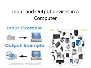
Input Devices
Input Devices
In electronics, all input devices will change an energy type
(kinetic, sound, light etc) into
electrical
energy.
Copy the following symbols and energy changes into your
workbook:
INPUT DEVICES
The Microphone
Energy Change: Sound
Electrical
Symbol:
Photovoltaic (solar) Cell
Energy Change: Light
Electrical
Symbol:
t
Thermistor
Energy Change: Heat
Electrical
Symbol:
Temperature Up, Resistance Down (TURD)
LDR
Energy Change: Light
Electrical
Symbol:
Light Up, Resistance Down (LURD)
Output Devices
Output Devices
In electronics, all output devices will change
electrical
energy
into another energy type (kinetic, sound, light etc).
Copy the following symbols and energy changes into your
workbook:
OUTPUT DEVICES
Loudspeaker
Energy Change: Electrical
Sound
Symbol:
Lamp
Energy Change: Electrical
Light
Symbol:
Motor
Energy Change: Electrical
Rotational Kinetic
Symbol:
M
Relay
Energy Change: Electrical
Kinetic
Symbol:
When current passes through the ‘box’, it
becomes magnetised and closes the switch. Relay
switches are used to allow low voltage circuits to
switch on high voltage ones.
OUTPUT DEVICES – THE DIODE
Symbol:
Direction of current flow for
conduction to take place
A diode is a component that is designed to only conduct current in one direction.
If connected the opposite way then it will
BLOCK
current.
OUTPUT DEVICES – THE LED
Energy Change: Electrical
Light
Symbol:
Direction of current flow
for LED to light.
An LED is a specific type of diode that emits light when current passes
through it.
It is normally paired with a resistor; this limits the size of the current so
the LED is not damaged.
OUTPUT DEVICES – THE LED
In questions, a circuit like that shown below will be given. Normally, the LED
voltage and current will be provided, along with the supply voltage.
To calculate the value of the series resistor, you must get the
resistor voltage
by taking the LED voltage away from the supply voltage!
As the components are in series, the LED current is the same as the resistor
current. V = IR can then be used to find the value of the resistor.
Example
Example:
i)
What is the purpose of the resistor in the above circuit?
ii)
Calculate the value of the series resistor.
Now, work through this example
as a class, completing the solution in your
workbook:
Now, solve the examples from your workbook in your
classwork jotter showing full working for each one.
10 mA
5 V
2.3 V
R?
KNOWLEDGE OF PHYSICS QUESTION
You have five minutes to answer the following question in your
workbook. The answer will be assessed by your teacher.
Other Devices
The Capacitor
The capacitor is a device which stores electrical charge. It consists of two metal plates
separated by an insulator.
Symbol:
A
V
S
V
As the capacitor charges:
•
The ammeter reading falls to zero.
•
The voltmeter reading increases until it equals V
S
.
The time taken for the capacitor to charge depends on:
•
The size of the capacitor.
•
The size of the resistor.
The Transistor
A transistor is an electrical switch; it only switches on when there is a certain
voltage across it. There are two different types:
npn transistor
base
collector
emitter
MOSFET
gate
drain
source
Summary
INPUT DEVICES
The Microphone
Energy Change: Sound
Electrical
Symbol:
Photovoltaic (solar) Cell
Energy Change: Light
Electrical
Symbol:
t
Thermistor
Energy Change: Heat
Electrical
Symbol:
Temperature Up, Resistance Down (TURD)
LDR
Energy Change: Light
Electrical
Symbol:
Light Up, Resistance Down (LURD)
OUTPUT DEVICES
Loudspeaker
Energy Change: Electrical
Sound
Symbol:
Lamp
Energy Change: Electrical
Light
Symbol:
Motor
Energy Change: Electrical
Rotational Kinetic
Symbol:
M
Relay
Energy Change: Electrical
Kinetic
Symbol:
When current passes through the ‘box’, it
becomes magnetised and closes the switch. Relay
switches are used to allow low voltage circuits to
switch on high voltage ones.
OUTPUT DEVICES 2
LED
Energy Change: Electrical
Light
Symbol:
Direction of current flow
An LED only conducts in one
direction as shown.
It is normally paired with a
resistor; this limits the size of
the current so the LED is not
damaged.
Direction of current flow for
conduction to take place
A diode is a component that is
designed to only conduct current in
one direction.
If connected the opposite way then
it will BLOCK current.
Diode
Symbol:
OUTPUT DEVICES 3
In questions, a circuit like that shown below will be given. Normally, the LED
voltage and current will be provided, along with the supply voltage.
To calculate the value of the series resistor, you must get the
resistor voltage
by taking the LED voltage away from the supply voltage!
As the components are in series, the LED current is the same as the resistor
current. V = IR can then be used to find the value of the resistor.
OTHER DEVICES
Transistors
A transistor is an electrical switch; it
only switches on when there is a certain
voltage across it. There are two
different types:
base
collector
emitter
gate
drain
source
npn transistor
MOSFET
Capacitor
Stores electrical energy
Symbol:
As the capacitor charges, the
voltage across it increases until it
equals the voltage supply.
The current in the circuit
decreases to zero.
Success Criteria: Being able to state the energy
changes involved in input and output devices and being
able to calculate the series resistor required for an LED
to operate correctly.
Tick off the box in your workbook when you have met the success criteria.
Now, use the space in your workbook to
produce a summary of electronic components.
You may wish to produce concise bullet points,
or draw a mind-map, or use any other useful
revision technique.
Explore the world of electronic components, input devices, and output devices through energy changes and symbol representations. Learn about LEDs, resistors, and energy conversions in a hands-on manner. Discover the role of various devices like microphones, solar cells, loudspeakers, and diodes in converting energy types. Delve into the world of electronics and enhance your knowledge in a practical way.

Download Presentation

Please find below an Image/Link to download the presentation.
The content on the website is provided AS IS for your information and personal use only. It may not be sold, licensed, or shared on other websites without obtaining consent from the author.If you encounter any issues during the download, it is possible that the publisher has removed the file from their server.
You are allowed to download the files provided on this website for personal or commercial use, subject to the condition that they are used lawfully. All files are the property of their respective owners.
The content on the website is provided AS IS for your information and personal use only. It may not be sold, licensed, or shared on other websites without obtaining consent from the author.
E N D
Presentation Transcript
Learning Intention: To learn various input and output devices, looking specifically at LEDs. Success Criteria: Being able to state the energy changes involved in input and output devices and being able to calculate the series resistor required for an LED to operate correctly.
Input Devices In electronics, all input devices will change an energy type (kinetic, sound, light etc) into electrical energy. Copy the following symbols and energy changes into your workbook:
INPUT DEVICES The Microphone Photovoltaic (solar) Cell Energy Change: Sound Electrical Energy Change: Light Electrical Symbol: Symbol: LDR Thermistor Energy Change: Heat Electrical Energy Change: Light Electrical t Symbol: Symbol: Light Up, Resistance Down (LURD) Temperature Up, Resistance Down (TURD)
Output Devices In electronics, all output devices will change electrical energy into another energy type (kinetic, sound, light etc). Copy the following symbols and energy changes into your workbook:
OUTPUT DEVICES Loudspeaker Motor Energy Change: Electrical Sound Energy Change: Electrical Rotational Kinetic M Symbol: Symbol: Lamp Relay Energy Change: Electrical Light Energy Change: Electrical Kinetic Symbol: Symbol: When current passes through the box , it becomes magnetised and closes the switch. Relay switches are used to allow low voltage circuits to switch on high voltage ones.
OUTPUT DEVICES THE DIODE A diode is a component that is designed to only conduct current in one direction. If connected the opposite way then it will BLOCK current. Symbol: Direction of current flow for conduction to take place
OUTPUT DEVICES THE LED Energy Change: Electrical Light Symbol: Direction of current flow for LED to light. An LED is a specific type of diode that emits light when current passes through it. It is normally paired with a resistor; this limits the size of the current so the LED is not damaged.
OUTPUT DEVICES THE LED In questions, a circuit like that shown below will be given. Normally, the LED voltage and current will be provided, along with the supply voltage. To calculate the value of the series resistor, you must get the resistor voltage by taking the LED voltage away from the supply voltage! As the components are in series, the LED current is the same as the resistor current. V = IR can then be used to find the value of the resistor.
Example Now, work through this example as a class, completing the solution in your workbook: Example: 10 mA 2.3 V 5 V R? i) ii) Calculate the value of the series resistor. What is the purpose of the resistor in the above circuit? Now, solve the examples from your workbook in your classwork jotter showing full working for each one.
KNOWLEDGE OF PHYSICS QUESTION You have five minutes to answer the following question in your workbook. The answer will be assessed by your teacher. The picture shows a car brake light. Use your knowledge of physics to explain why car manufacturers now select LEDs for brake lights, rather than using bulbs.
The Capacitor The capacitor is a device which stores electrical charge. It consists of two metal plates separated by an insulator. Symbol: As the capacitor charges: The ammeter reading falls to zero. The voltmeter reading increases until it equals VS. V VS The time taken for the capacitor to charge depends on: The size of the capacitor. The size of the resistor. A
The Transistor A transistor is an electrical switch; it only switches on when there is a certain voltage across it. There are two different types: npn transistor MOSFET collector drain base gate source emitter
INPUT DEVICES The Microphone Photovoltaic (solar) Cell Energy Change: Sound Electrical Energy Change: Light Electrical Symbol: Symbol: LDR Thermistor Energy Change: Heat Electrical Energy Change: Light Electrical t Symbol: Symbol: Light Up, Resistance Down (LURD) Temperature Up, Resistance Down (TURD)
OUTPUT DEVICES Loudspeaker Motor Energy Change: Electrical Sound Energy Change: Electrical Rotational Kinetic M Symbol: Symbol: Lamp Relay Energy Change: Electrical Light Energy Change: Electrical Kinetic Symbol: Symbol: When current passes through the box , it becomes magnetised and closes the switch. Relay switches are used to allow low voltage circuits to switch on high voltage ones.
OUTPUT DEVICES 2 LED Diode Symbol: Energy Change: Electrical Light Direction of current flow for conduction to take place Symbol: Direction of current flow A diode is a component that is designed to only conduct current in one direction. If connected the opposite way then it will BLOCK current. An LED only conducts in one direction as shown. It is normally paired with a resistor; this limits the size of the current so the LED is not damaged.
OUTPUT DEVICES 3 In questions, a circuit like that shown below will be given. Normally, the LED voltage and current will be provided, along with the supply voltage. To calculate the value of the series resistor, you must get the resistor voltage by taking the LED voltage away from the supply voltage! As the components are in series, the LED current is the same as the resistor current. V = IR can then be used to find the value of the resistor.
OTHER DEVICES Capacitor Transistors Stores electrical energy A transistor is an electrical switch; it only switches on when there is a certain voltage across it. There are two different types: Symbol: As the capacitor charges, the voltage across it increases until it equals the voltage supply. npn transistor MOSFET collector drain base The current in the circuit decreases to zero. gate source emitter
Success Criteria: Being able to state the energy changes involved in input and output devices and being able to calculate the series resistor required for an LED to operate correctly. Tick off the box in your workbook when you have met the success criteria.
Now, use the space in your workbook to produce a summary of electronic components. You may wish to produce concise bullet points, or draw a mind-map, or use any other useful revision technique.