Electromagnetic Waves: Transmission Lines Reflection
The concepts of transmission lines, reflections, and impedance in the study of applied electromagnetic waves. Dive into the implications and applications for these phenomena with the guidance of Prof. David R. Jackson's notes for Fall 2024.
Download Presentation

Please find below an Image/Link to download the presentation.
The content on the website is provided AS IS for your information and personal use only. It may not be sold, licensed, or shared on other websites without obtaining consent from the author.If you encounter any issues during the download, it is possible that the publisher has removed the file from their server.
You are allowed to download the files provided on this website for personal or commercial use, subject to the condition that they are used lawfully. All files are the property of their respective owners.
The content on the website is provided AS IS for your information and personal use only. It may not be sold, licensed, or shared on other websites without obtaining consent from the author.
E N D
Presentation Transcript
ECE 3317 Applied Electromagnetic Waves Prof. David R. Jackson Fall 2024 Notes 10 Transmission Lines (Reflection and Impedance) 1
Reflection Consider a transmission line that is terminated with a load: Z ( ) I z z g + ( ) +- Z V Z V z 0 g L - z = 0 + + R G j L j C = Z 0 Note: In the frequency domain notes, the load is always at z = 0. Voltage and current on the line: A Z B Z + = + z z + = ( ) V z Ae Be z z ( ) I z e e 0 0 ( ) z ( ) z V V + ( ) z ( ) z I I + 2
Reflection (cont.) Important point: The forward-traveling and backward-traveling wave amplitudes are the amplitudes that describe the two waves in sinusoidal steady-state (after all bounces have died down and we are in steady state). Z ( ) I z z g + ( ) +- Z V Z V z 0 g L - z = 0 A Z B Z + = + z z = + z z ( ) I z e e ( ) V z Ae Be 0 0 A = amplitude of net forward-traveling wave B = amplitude of net backward-traveling wave 3
Reflection (cont.) Z ( ) I z z g + ( ) +- Z V Z V z 0 g L - z = 0 + + R G j L j C = Z 0 + = + z z ( ) V z Ae Be A Z B Z + = z z ( ) I z e e ( ) 0 = (0) V Z I At the load (z = 0): 0 0 L 1 Z ( ) + = Hence, we have A B Z A B L 0 Z Z 1 L Z Z Z Z + = 1 1 B A L L or = 0 B A Z Z 0 0 + 1 L 0 4
Reflection Coefficient ( ) ( ) 0 0 V V We define the load reflection coefficient: L + B A + = + z z ( ) = V z Ae Be Hence L + = = z ( ) ( ) z V V z Ae Be + z We then have, from the last slide, Z Z 1 L B A = = 0 L Z Z + 1 L 0 or + Z Z Z Z = This is the same formula that we had in the time domain, but here the load impedance and the characteristic impedance may be complex. 0 L L 0 L 5
Voltage and Current We can then use B = LAto write: ( ) + z z = + ( ) V z A e e L 1 Z ( ) + = z z ( ) I z A e e L 0 + Z Z Z Z = 0 L L 0 L Note: The generator (source) will determine the unknown (complex) constant A. 6
Impedance We define the input impedance at any point z on the line: Z ( ) I z z g + ( ) +- Z V V z Z L g - z 0 z = 0 Z in ( ) ( ) I z V z ( ) z Z in The input impedance is the impedance seen looking to the right. 7
Impedance (cont.) Z ( ) I z z g + ( ) +- V Z V z Z g L - z 0 z = 0 Z in ( ) I z z ( ) ( ) I z V z + - ( ) z ( ) Z Z Z Z V z L 0 in in z = z 0 Note: The input impedance does not care what is to the left of the point z. (What is to the left of the point z only affects the amplitude level of the voltage and current.) 8
Impedance (cont.) We then have: ( ) + + z z A e e ( ) z L = Z 1 Z in ( ) + z z A e e L 0 Canceling the constant A, we have: + + z z e e e e ( ) z = Z Z L in 0 + z z L or + + 2 z 1 1 e e ( ) z = Z Z L in 0 + 2 z L 9
Impedance (cont.) = z d e e Now let z =- d : (Here d is the distance from the load.) Z ( ) z g I d + ( ) +- V d V Z Z g L 0 - d ( ) Z d z = 0 in + 2 d 1 1 e e ( ) = Z d Z L in 0 2 d L 10
Impedance (cont.) At the beginning of the line (d = l) we have: + 2 l 1 1 e e ( ) = Z l Z L in 0 2 l L l = length of line ( ) Z l I z g + +- ( ) V Z Z l V g L 0 - l Z z = 0 in 11
Impedance (cont.) We can derive a new form ( tangent form ) for the input impedance. Substituting for the load reflection coefficient, we have: + + 2 z 1 1 e e ( ) z = Z Z L in 0 + 2 z L + + Z Z Z Z Z Z Z Z + + 2 z 1 e 0 L = 0 L Z 0 + 2 z 1 e 0 L 0 L ( ( ( ( ) ( ) ( ) ) e ) ) + + + + 2 z Z Z Z Z Z Z Z Z e e = 0 0 L L Z 0 + 2 z 0 0 L L ( ( ) ) + + + + z z Z Z Z Z e Z Z Z Z e e = 0 0 L L Z 0 + z z 0 0 L L 12
Impedance (cont.) Rearranging the expression, we have: ( ( ) ) ( ( ) ) + + + + z z Z Z Z Z e e Z Z Z Z e e ( ) z = 0 0 L L Z Z in 0 + z z 0 0 L L ( ) z ( ) z + + + + z z z z Z e e Z e e 0 L = Z ( ) ( ( ) ) z 0 + + + z z Z e e Z e e 0 L ( ) ) ) ) ) ) ( ( ) ) ( + 2cosh 2sinh 2sinh 2cosh Z z z Z Z z 0 L = Z ( ( ) ( 0 Z 0 L ( ( tanh tanh Z Z Z Z z z = 0 L Z 0 0 L 13
Impedance (cont.) ( ) ( ) ( ) = = tanh tanh tanh z d d Now let z =- d : Z ( ) z g I d + ( ) +- V d V Z Z g L 0 - d ( ) Z d z = 0 in ( ( ) ) + + tanh tanh Z Z Z Z d d ( ) = 0 L Z d Z in 0 0 L d = distance from load 14
Impedance (cont.) At the beginning of the line (d = l) we have: ( ) ( ) + + tanh tanh Z Z Z Z l l ( ) = 0 L Z l Z in 0 0 L l = length of line ( ) Z l I z g + +- ( ) Z V Z l V L g 0 - l Z z = 0 in 15
Impedance (cont.) Limiting Cases = = 0 l Z Z 1) General (lossy) line: in L 2) Lossless line: = = = 0 0 Z Z in L ( )( ) = + j L G + j C = 0 R j LC These limiting cases agree with circuit theory. 16
Impedance (cont.) Limiting Cases (cont.) = 0( ) l Z Z complex 3) Lossy infinite line: in ( ) ( ) Proof: + + tanh tanh Z Z Z Z l l = 0 L Z Z in 0 0 L = + , 0 j ( ) l tanh 1 l 1 2 1 2 ( ( ) ) l l e e ( ) ( ) + + sinh cosh l l 2 2 2 l l j l 1 1 1 1 e e e e e e ( ) = = = = Note: tanh l 2 2 2 l l j l + l l e e 17
Impedance (cont.) Limiting Cases (cont.) 4) Matched load (ZL = Z0): ( ) ( ) + + tanh tanh Z Z Z Z l l = 0 L Z Z in 0 0 L ( ) ( ) + + tanh tanh Z Z Z Z l l = 0 0 Z Z in 0 0 0 = Z Z (independent of line length!) in 0 18
Impedance (cont.) Lossless Case ( )( ) = + = + j L G + j C = j R j LC ( ) ( ) x = tanh tan jx j ( ) ( ) ( ) Use = j l = tanh tanh tan l j l ( ( ) ) + + tan tan Z Z jZ jZ l l = 0 L Z Z We then have in 0 0 L where 2 2 2 2 f f c f = = = = = = = 0 = LC d 0 c / / c r r d d 0 r r r r 19
Impedance (cont.) Summary of final formula for a lossless line: Z Z Z L 0 in l ( ( ) ) + + tan tan Z Z jZ jZ l l = 0 L Z Z in 0 0 L 2 c f = = = LC = = 0/ 0 d r r d 20
Impedance (cont.) For a lossless line: The input impedance repeats every one-half wavelength. The complex voltage and current repeat every wavelength. The complex voltage and current become their negatives after one-half wavelength. The magnitude of the voltage and current repeat every one-half wavelength. ( ( ) ) + + 2 tan tan Z Z jZ jZ d d d = = 0 L = Z Z 2 d in 0 d 0 L d Recall: = 2 j 1 1 e = j e z 1 Z ( ) ( ) = j z + j z j z + j z 2 = + z = ( ) V z A e e ( ) I z A e e L L 0 d 21
Impedance (cont.) Special Cases of the Load on a Lossless Line Short-circuit line Z Z = Z 0 0 L in l ( ( ) ) + + tan tan Z Z jZ jZ l l = 0 L Z Z in 0 0 L ( ) ( ) = 0tan Z jZ l = 0tan 2 / Z jZ l or in in d 22
Impedance (cont.) Short-circuit line ( ) Z Z = Z 0 = 0tan X Z l 0 L in = Z jX in in in l or ( ) = 0tan 2 / X Z l in d OC OC OC Open circuit The line is one-fourth of a wavelength long. ( )( 2 / d = X in ) = / 4 / 2 l d inductive l /2 3 /2 5 /2 capacitive 23
Impedance (cont.) Low frequency: Short-circuit line ( ) X Z l ( ) = 0tan X Z l in 0 in ( ) L C = LC l ( ) = Ll Ll Z in ( ) X Ll Cl in Ignore (shorted) l 24
Impedance (cont.) Special Cases of the Load on a Lossless Line Open-circuit line Z Z = Z L 0 in l ( / ) ( ) + 1 / tan tan ( ( ) ) j Z Z + l + + tan tan Z Z jZ jZ l l = 0 L Z Z = 0 L Z Z ( ) ( ) in 0 Z Z j l in 0 0 L 0 L ( ) ( ) = 0cot Z jZ l = 0cot 2 / Z jZ l or in in d 25
Impedance (cont.) Open-circuit line Z Z = Z ( ) = 0cot X Z l L 0 in in = Z jX or l in in ( ) = 0cot 2 / X Z l in d OC OC OC Short circuit X The line is one-fourth of a wavelength long. ( )( 2 / d = in ) = / 4 / 2 l d inductive l 2 3 capacitive 26
Impedance (cont.) Low frequency: ( Z Open-circuit line ) 0/ X l ( ) = 0cot X Z l in in 1 LC l L C = 1 Cl = ( ) Ll = 1/ B X Z (for reactive element) in in Cl in ( ) Ignore (small reactance compared to capacitor) B Cl in l 27
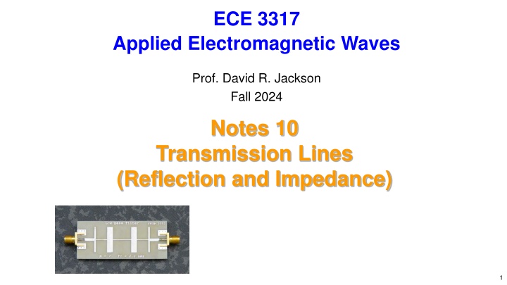
Filter Application Microstrip Filter (Here is an application with microstrip lines being used to realize L and C elements.) 28
Appendix: Summary of Formulas General Lossy Case + Z Z Z Z ( ( ) ) + + tanh tanh Z Z Z Z d d = 0 L = 0 L Z Z L in 0 0 L 0 L + + R G j L j C + 2 d 1 1 e e = Z = Z Z L 0 in 0 2 d L ( )( ) = + j L G + j C R ( ) + z z = + ( ) V z A e e L = + j 1 Z ( ) + = z z ( ) I z A e e L g = 2 / 0 29
Appendix: Summary of Formulas Lossless Case + Z Z Z Z ( ( ) ) + + tan tan = Z Z jZ jZ d d 0 L = 0 L Z Z L in 0 0 L 0 L L C = Z + 2 j d 1 1 e e 0 = Z Z L in 0 2 j d L 2 2 f = = = = LC c ) ( d d j z + j z = + ( ) V z A e e = 0/ L d r r ( ) 1 Z = ( short in ( ) 0tan Z jZ l j z + j z = ( ) I z A e e L ) = open in 0cot Z jZ l 0 30
