E-175 Fueling Procedures Training
Learn about the fueling procedures for Mesa Airlines, Inc.'s E-175 aircraft. Understand the importance of electrostatic bonding to prevent sparks during fueling operations. Discover the approved bonding locations on the E-175, tank specifications, fuel control panel features, and how to conduct automatic refueling safely and efficiently.
Download Presentation

Please find below an Image/Link to download the presentation.
The content on the website is provided AS IS for your information and personal use only. It may not be sold, licensed, or shared on other websites without obtaining consent from the author.If you encounter any issues during the download, it is possible that the publisher has removed the file from their server.
You are allowed to download the files provided on this website for personal or commercial use, subject to the condition that they are used lawfully. All files are the property of their respective owners.
The content on the website is provided AS IS for your information and personal use only. It may not be sold, licensed, or shared on other websites without obtaining consent from the author.
E N D
Presentation Transcript
Mesa Airlines, Inc. E-175 Fueling Procedures Training
Electrostatic Bonding Always bond an aircraft prior to starting the fueling operation to prevent an electric spark. The fuel tender, aircraft and nozzle MUST be bonded. Warning: A static electric spark could cause an explosion or a fire.
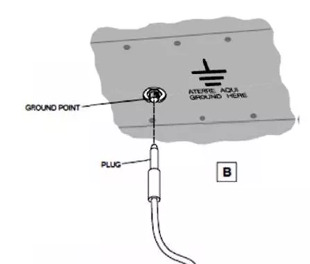
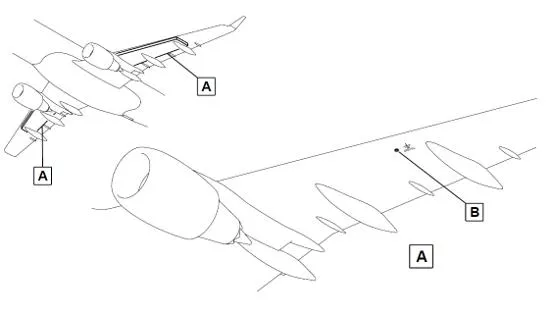
E-175 Bonding Locations The E-175 has 3 approved bonding locations: Left or Right Wing Leading Edge Right Main Landing Gear The ports on the underside of the wing are plug style and can be bonded using a bayonet connector. (Pictured: top) The right main landing gear has a metal clip that a clamp style connector can be secured to. (Pictured: bottom, facing forward)
E-175 Tank Specifications Tank Capacities Usable Fuel Location Unusable Fuel Total Volume Left Main Tank 10392.5 lbs. (4714 kg) 75 lbs. (34 kg) 10467.5 lbs. (4748 kg) Right Main Tank Total Fuel Capacity (both tanks combined) 20935 lbs. (9495.5 kg) When fueling, always monitor the tank quantities. The imbalance of fuel between the left and right main tanks must NEVER exceed 794 lbs. If this limit is exceeded, the aircraft could shift causing injury or damage to equipment and the aircraft. Maximum Tank Imbalance E-175 794 lbs. (360 kg)
E-175 Fuel Control Panel 1. REFUELING Switch 2. REFUEL SELECTION Switch 3. LH/RH REFUELING Indication Lights 4. Repeater Indicator 5. DEFUELING Indication Light 6. POWER SELECTION Switch 7. DEFUELING Switch 8. INCR/DECRT Switch
Automatic Refueling First, ensure the aircraft is properly bonded via an approved bonding method, and open the fuel panel under the wing. Automatic mode should always be used when operational. Make sure the REFUELING switch (1) and the DEFUELING switch (7) are both in the CLOSED position. Confirm the LH and RH refueling indication lights (3) are off. Make sure the defueling indication light (5) is off. Set the REFUEL SELECTION switch (2) to the AUTO position. Set the repeater indicator (4) to the necessary fuel quantity using the INCR/DECRT switch (8).
Automatic Refueling Remove the cap from the fuel adaptor (fuel hose connector). Visually check for contamination or cracks in the fuel connectors. If any contamination is present, contact the flight crew. Connect the fuel nozzle to the fuel adaptor. Pressurize the fuel system to 40 PSI (276 kPa). THE NOZZLE MUST NEVER BE PRESSURIZED ABOVE 50 PSI (345 kPa) Make sure the LH and RH refueling indication lights (3) come on and there is no fuel flow.
Automatic Refueling Set the REFUELING switch (1) to the OPEN position, and make sure the LH and RH refueling indication lights (3) go off. Stop the fueling if the screen blacks out or if STOP R OVER, STOP L OVER or STOP L/R OVER appears. If this precaution is not obeyed, fuel leaks can occur and/or cause damage to the aircraft. WHEN FUELING, CONTINOUSLY MONITOR THE TANK QUANTITIES TO ENSURE THE MAXIMUM TANK IMBALANCE IS NOT EXCEEDED ON THE MAIN TANKS. When the necessary fuel quantity is obtained, the LH and RH refueling indication lights (3) will come on and the fuel flow stop.
Automatic Refueling Set the REFUELING switch (1) to the CLOSED position. If the aircraft batteries were used, move the POWER SELECTION switch (6) from BATTERY back to the NORMAL position. Remove pressure from the fuel nozzle to 0 PSI (0 kPa). Disconnect the fuel nozzle from the fuel adaptor. Install the cap on the fuel adaptor and securely latch the open panel. Disconnect the bonding connection from the aircraft.
Manual Refueling If the automatic mode is unavailable, manual pressure refueling is permitted. All set-up procedures and safety precautions to prepare for automatic refueling must be followed for manual refueling.
Manual Refueling First, ensure the aircraft and fuel tender are bonded via an approved method. Open the refueling panel and check to make sure: The LH and RH refueling indication (3) and defueling indication (5) lights are all off. Verify the REFUELING Switch (1) is CLOSED. Set the REFUEL SELECTION switch (2) to the MANUAL position.
Manual Refueling Remove the cap from the fuel adaptor. Visually check for contamination or cracks in the fuel connectors. If any contamination is present, contact the flight crew. Connect the fuel nozzle to the fuel adaptor. Pressurize the fuel system to 40 PSI (276 kPa). THE NOZZLE MUST NEVER BE PRESSURIZED ABOVE 50 PSI (345 kPa) Make sure the LH and RH refueling indication lights (3) come on and there is no fuel flow.
Manual Refueling Set the REFUELING switch (1) to the OPEN position and make sure that the LH and RH refueling indication lights (3) go off. WHEN FUELING, CONTINOUSLY MONITOR THE TANK QUANTITIES TO ENSURE THE MAXIMUM TANK IMBALANCE IS NOT EXCEEDED ON THE MAIN TANKS. Stop the fueling if the screen blacks out or if STOP R OVER, STOP L OVER or STOP L/R OVER appears. If this precaution is not obeyed, fuel leakage can occur and cause damage to the aircraft. When the necessary fuel quantity is obtained, set the REFUELING switch (1) to the CLOSED position. Make sure that the LH and RH refueling indication lights (3) come on and the fuel flow stops.
Manual Refueling At the desired fuel quantity, set the REFUELING switch (1) to the CLOSED position. Ensure the LH and RH indication lights (3) come on and the fuel flow stops. Remove pressure from the fuel nozzle to 0 PSI (0 kPa). Disconnect the fuel nozzle from the fuel adaptor. Install the cap on the fuel adaptor and securely latch the open panel. Disconnect the bonding connection from the aircraft.
Gravity Refueling (Overwing) If the pressure refueling system is unavailable or inoperative, gravity (overwing) refueling is permitted. All procedures and safety precautions to prepare for automatic/manual refueling must be followed for gravity (overwing) refueling. Solid protective wing mats MUST be utilized to prevent damage and scratches to the wing surface. Mesh or bar mats are NOT acceptable.
Gravity Refueling First, ensure the fuel tender and aircraft are bonded via an approved method. For the LH fuel tank, open the LH gravity filler cap. For the RH fuel tank, open the RH gravity filler cap.
Gravity Refueling Put the fuel nozzle into the gravity filler port. Begin dispensing the fuel and monitor the fuel quantity in the tank(s). WHEN FUELING, CONTINOUSLY MONITOR THE TANK QUANTITIES TO ENSURE THE MAXIMUM TANK IMBALANCE IS NOT EXCEEDED ON THE MAIN TANKS. The tanks may be fueled one at a time, provided the maximum tank imbalance is not exceeded. Fueling both tanks at the same time utilizing two fuelers is also permitted.
Gravity Refueling Remove the fueling nozzle from the gravity filler port after obtaining the correct fuel quantity in the tank(s). Replace the gravity filler cap(s). Latch any open panels securely shut and disconnect the bonding connection from the aircraft.
Suction Defueling When defueling, observe all safety precautions. Only suction defueling is permitted without Maintenance personnel present. For gravity defueling, contact Mesa Dispatch. The aircraft must be connected to ground power. If external ground power is not available, aircraft batteries may be used. Ensure the aircraft and fuel tender are properly bonded and open the fuel panel.
Suction Defueling Make sure the refueling (3) and defueling (5) indication lights are off and the REFUELING Switch (1) is CLOSED. Remove the cap from the fuel adaptor and connect the fuel nozzle. Open the valve handle on the fuel nozzle. Set the DEFUELING switch (7) to the OPEN position, and make sure that the defueling indication light (5) comes on.
Suction Defueling In the flight deck, a second agent will locate the overhead FUEL CONTROL PANEL. Set the XFEED switch as follows: To defuel both tanks, set to the LOW 2 position To defuel onlythe LH tank, set to the OFF position To defuel onlythe RH tank, set to the LOW 1 position.
Suction Defueling Apply suction to defuel and do not exceed -4 PSI (-27 kPa). WHEN FUELING, CONTINOUSLY MONITOR THE TANK QUANTITIES TO ENSURE THE MAXIMUM TANK IMBALANCE IS NOT EXCEEDED ON THE MAIN TANKS. When the desired tank quantities are reached, set the DEFUELING switch (7) to the CLOSED position. CAUTION: When fully defueling the tank, you must stop when the indication shows 0. There is a still small quantity of fuel left in the tank that prevents damage to the fuel pump. Continuing to apply suction after reaching a reading of 0 will cause damage to the fuel pump system.
Suction Defueling When defueling is compete, make sure the defueling indication light (5) goes off. Reset the XFEED switch in the flight deck to OFF. Close the handle on the fuel nozzle and disconnect it from the aircraft. If the aircraft batteries were used, move the POWER SELECTION switch (6) from BATTERY back to the NORMAL position. Install the cap to the fuel adaptor and securely latch the open panels. Disconnect the aircraft bonding point.
E-175 Fueling Procedures Training This concludes the Mesa Airlines, Inc. E-175 Fueling Procedures Training. Please continue to the test to finish this course. You must pass with a score of 75% or better. Print and keep your certificate on file at your station.
