Dynamic Voltage and Frequency Scaling in Advanced VLSI
Explore the concepts of Dynamic Voltage and Frequency Scaling (DVFS) in Advanced VLSI design. Learn about the impact on clocking, STA, and testing, as well as considerations for selecting the right voltage and frequency settings. Discover how controlling voltage affects power consumption and computational efficiency, and the strategies for optimizing V/F points in core processing. Uncover the balance between performance, energy consumption, and battery life in VLSI design.

Download Presentation

Please find below an Image/Link to download the presentation.
The content on the website is provided AS IS for your information and personal use only. It may not be sold, licensed, or shared on other websites without obtaining consent from the author.If you encounter any issues during the download, it is possible that the publisher has removed the file from their server.
You are allowed to download the files provided on this website for personal or commercial use, subject to the condition that they are used lawfully. All files are the property of their respective owners.
The content on the website is provided AS IS for your information and personal use only. It may not be sold, licensed, or shared on other websites without obtaining consent from the author.
E N D
Presentation Transcript
EE 194 Advanced VLSI Spring 2018 Tufts University Instructor: Joel Grodstein joel.grodstein@tufts.edu Lecture 6: Discrete voltage and frequency switching 1
DVFS What we ll cover DVFS: why we care What is DVFS Effects on clocking Effects on STA Effects on testing How does the voltage get to the transistors? How do you choose the right voltage & freq? EE 194/Adv. VLSI Joel Grodstein 2
Old slide from power/scaling We said that: energy to switch one node is .5CV2 power=?????? this assumed that switches/sec=f; i.e., every node switches once every cycle ????? ????? ?? =.5CV2f ??? In more detail: power=?????? ????? ????? ?? ?????? ??? = (.5CV2) AF f ????? AF is the activity factor potentially different for every node says (on average) how many switches to expect per cycle Ceffective AF C combines AF and C into one number: so power= 5CeffV2f EE194/Adv VLSI Joel Grodstein 3
And from STA Delay 1/V Remember, we used this for speed binning EE 194/Adv. VLSI Joel Grodstein 4
And so we conclude Energy to perform a computation V2 since energy to switch one node is .5CV2 Power V2f and f V, so power V3 Controlling voltage is a big hammer in controlling power Raise voltage by 10% Thus you can also raise frequency by 10% You get 10% more computations done in the same time But power goes up 30% and energy goes up 20% Obvious question: what is the best V/F point to use? Always the lowest possible V that the process allows? Does this sound sort of like speed binning? Let s see EE 194/Adv. VLSI Joel Grodstein 5
Best V/F for one core Start small; assume we only have one core How do we choose the best V/F point?: We ve already talked about setting Vdd for binning. The keys: raise Vdd and devices run faster, so you can increase clock speed. But energy to perform a calculation goes up quadratically. And power goes up cubically (though for a shorter time) So when you raise V and f one good thing happens (you go faster). two bad things happen (more energy and power). EE 194/Adv. VLSI Joel Grodstein 6
Just use the lowest V? If we just run at lowest possible V that the process supports We minimize energy and power We maximize battery life. So why not? Low V means low F Who wants to buy a phone that can t play Angry Birds fast enough? Many tasks have real-time requirements (you must meet a minimum frame rate on an MPEG decoder) Lowest V may simply not be fast enough for some tasks But fine for others (reading e-mail) EE 194/Adv. VLSI Joel Grodstein 7
Dynamic usage patterns Your cell phone usage changes frequently. You play a fancy-graphics video game. Then you read some e-mail Long hours doing nothing What s the right voltage for each usage? Video game needs high voltage (and very high power) Read e-mail: you can drop V and F Doing nothing: you can drop V and F quite low If you always use high V and F battery dies Always use low V and F cannot play the video game There is no single voltage that is always best for our single-core CPU Changing V/F is too powerful a tool to not use it EE 194/Adv. VLSI Joel Grodstein 8
Battery: Set by size and weight limits ... Battery rating: 55 W-hour. At 2.3 GHz, Intel Core Duo CPU consumes 31 W running a heavy load - under 2 hours battery life! And, just for CPU! 46x more energy than iPod nano battery. And iPod lets you listen to music for 14 hours! Almost full 1 inch depth. Width and height set by available space, weight. At 1 GHz, CPU consumes 13 Watts. Energy saver option uses this mode ... EE194/Adv VLSI Joel Grodstein 9
The best V/F for a multi-core CPU We ve decided there is no single best V and F for a single-core CPU. What about a multi-core CPU? Probably the same thing will be true Let s see some of the issues in more detail, though EE 194/Adv. VLSI Joel Grodstein 10
Range of server power SkyLake server: Xeon server 8180M (Platinum): Biggest SkyLake available when this slide was made 28 cores, 2.5 GHz base, 3.8GHz boost Say 1 core at 2.5GHz uses 5-10 watts (depending on code), boost=7W*(3.8/2.5)3 25W Dual-socket server 56 cores A dual-socket 56-core server may handle diverse use models: Anything from one to very many people logged in Any person could run a 4-core compute-intensive job, or just editing or reading e-mail. Very wide range of power demands 1 person running e-mail = 5W 14 people with 4 cores of boost = 1400W EE 194/Adv. VLSI Joel Grodstein 11
Who cares about server power? A server is plugged in; there is no battery So why do we care about power? Why not just run everything full speed ahead always? Why servers care about power Air conditioning is expensive. So is electricity 205W max package power dissipation for air cooling, and liquid cooling is expensive If you exceed your power budget, things start to melt. Server farms in Norway? What good is a 56-core server if you can only use 205/25 8 cores at once per die? EE 194/Adv. VLSI Joel Grodstein 12
Server V/F tradeoffs If only a few cores are being used: each is free to crank up V & F as needed but saving energy still saves $$ When we use lots of cores: either many people doing small jobs or medium number doing compute-intensive jobs we must crank down the V & F of each one. top still tells everyone they re getting an entire CPU; but it s a slower CPU than if fewer cores were being used! Conclusion: benchmarking can be unreliable if you re sharing the machine with other users EE 194/Adv. VLSI Joel Grodstein 13
Discrete Voltage and Frequency Switching (DVFS) OK, now we re ready to define what DVFS is We ve seen that switching V/F points on the fly is useful for one core and for multicore. We ve already talked about setting V for binning raise V and devices run faster lower V and devices run slower, but you save power Binning picked the lowest V that could hit a target freq. Raising(lowering) V hurts(helps) power cubically DVFS is dynamically switching V/F points according to user demand, to use as little power as needed to meet user requirements avoid burning up the chip when user requirements are unreasonable EE 194/Adv. VLSI Joel Grodstein 14
DVFS Design Issues What is the hardware granularity which the voltage and frequency can be controlled? Entire chip at once Cache at the different voltage than the cores Numerous voltage islands on a single chip Why do we care? Different parts of the chip may want to be at different V/F More details later ECEC 623 Mark Hempstead 15
DVFS Design Issues How long does it take to switch to a new (V,f)? One cycle? A few ns? A few s? Why do we care? Lower voltage whenever we have a stall when we have a long stall (e.g., cache miss) O/S changes voltage for load balancing Again, more details later ECEC 623 Mark Hempstead 16
A simple plan Pick one of multiple V/F points When you need lots of computes for a non-parallel problem, you pick high V/F and live with the power drain (and energy inefficiency) Let other cores go unused if needed When you can, reduce Vdd and also freq and increase efficiency If you see the chip getting too hot, then reduce V/F right away before you melt the package (or any body parts!) DVFS is important because use models change dynamically But wait: nowadays we keep our phones busy running YouTube for background music, even if we re just reading e-mail? Does that mean we can never turn down the voltage? Hold that thought; we ll talk more about YouTube when we get to dark silicon. EE 194/Adv. VLSI Joel Grodstein 17
Next up circuit design DVFS means changing voltage and frequency on the fly It affects circuit design in multiple ways clocking must deal with multiple V and F ditto for STA Another question: how do you get so many voltages to the transistors? We ll talk about FIVR EE 194/Adv. VLSI Joel Grodstein 18
Multiple V/F domains The best V/F will change over time Should it also be different in different places at the same time? The FPUs could use high F while the cache runs slow Or vice versa, during a cache miss! Memory controller always runs slower than the CPU The circuitry that reads/writes a disk can usually run really slow This is called voltage islands How fast can you change V/F? depends on the system; not on a cycle-by- cycle basis EE 194/Adv. VLSI Joel Grodstein 19
Domain crossing Domains must talk to each other! We ve seen this before: clock crossings and BGFs Now we know why it s so important But the BGF clock ratios will change on the fly! Not so trivial any more. EE 194/Adv. VLSI Joel Grodstein 20
BGF conditional clocks and DVFS PLL 15x 9x Start with core=1.5GHz, uncore=900 MHz BGF will conditionalize 2nd, 5th, 7th, 10th, 12th, 15th core clocks EE 194/Adv. VLSI Joel Grodstein 21
So BGF clocking must coordinate with DVFS Not surprising Not simple either PLL 12x 9x Start with core=1.5GHz, uncore=900 MHz BGF will conditionalize 2nd, 5th, 7th, 10th, 12th, 15th core clocks Now move to core=1.2 GHz, uncore still 900 MHz We skip 3rd, 7th, 11th clocks We need a different clock-skip plan! I.e., the BGF clocking must change dynamically. EE 194/Adv. VLSI Joel Grodstein 22
PLL changing frequency Clkin Clkout Phase comparator VCO / N What happens when the /N changes its N? Relocking to the new frequency takes time Most PLLs have their freq jump around unpredictably while relocking Some PLLs guarantee smooth transition Timing issue: We know that timing worked at the old V/F, and at the new V/F But what about all of the intermediate V/F points that we pass through dynamically? How do you prevent timing violations while F is changing? That s a HW problem! EE 194 Joel Grodstein 23
DVFS and STA Simple un-binned design: A core runs at one voltage It either meets frequency or doesn t Binned design Any given core may be sold at one of multiple F It runs at the minimum V that meets that F We ran STA at TT, found post-silicon violations via lots of testing Any single die runs at the same V/F forever Testing was because each chip has only one V/F (remember our HW?) DVFS design Every single chip must dynamically switch between various V/F points STA and testing issues? Same STA issues as for speed binning! Test issues are far worse; must test every die at every DVFS freq Must do this for up to 50 domains on each die! So we run STA at TT again, but now need lots of testing Testing is slow and expensive and unavoidable EE 194/Adv. VLSI Joel Grodstein 24
More DVFS and STA Assume we run STA at TT Does it matter what V we run STA at? Will different paths show up? Yes. Relative path delays change at different V Some paths are gate-delay dominated; some are wire dominated Which paths are worse at low(high) V? High V speeds up gate delays but not wires So gate-dominated paths are worse at low V, wires worse at high V EE 194/Adv. VLSI Joel Grodstein 25
More DVFS and STA We want STA to identify the slowest paths, so we can design them faster. Any problems if we run STA at high V? Gates seem to be real fast Wires paths show up and get fixed Then the real chip lowers V, and the gate-dominated paths hurt you. Any problems if we run STA at low V? Similar issue, but just the reverse On real silicon, suddenly the wire-dominated paths show up at high V Run STA at an intermediate V? Now we get smaller failures on silicon, but in both kinds of paths Run STA twice; at both low and high V? This still misses some paths that are worse in the middle! The more points you run for STA, the closer you are (and the more work you do!) No perfect answer; but testing is your friend EE 194/Adv. VLSI Joel Grodstein 26
Issues with DVFS DVFS and voltage islands are great. But EE 194/Adv. VLSI Joel Grodstein 27
What do you show the customer? If the core can have 4 V/F points and the uncore has 2 that makes 8 combinations, each with their own total power Do you really advertise 8 V/F/power combos to customers? No. Each chip just has a base & boost that are advertised. The rest may be accessible to the O/S, or only by the chip s own software But binning is still complex see https://www.nextplatform.com/2017/07/11/x86-battle-lines- drawn-intels-skylake-launch/ Bin by # of cores, by boost speed, L3 size, memory speed, ... And we still have to test every combination, even if we don t advertise it. This is expensive! EE 194/Adv. VLSI Joel Grodstein 28
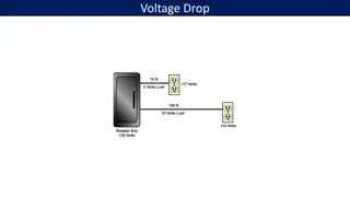
Problem with changing Vdd Package+die package wiring Motherboard VR die loading gnd gnd gnd DVFS is great. But there s an implementation issue. The die load changes fast and often; voltage drop across the package R changes with it. So how do you keep a steady V? Lots of dcap But now there s a problem: how do you change the V? EE 194/Adv. VLSI Joel Grodstein 29
Changing Vdd Package+die package wiring Motherboard VR die loading gnd gnd gnd Lots of Dcap lots of problems Driving lots of C through a big RLC is very slow To change Vdd quickly, you need lots of I - Lots of I lots of I2R loss - Remember: power loss charging a capacitor CV2 Reducing C would help both of these but would make Vdd noisy EE 194/Adv. VLSI Joel Grodstein 30
Low V waste power Package+die .5V package wiring 2V Motherboard VR die loading gnd gnd gnd Nvidia Pascal is 300 watts, so we must deliver 300 watts 600 amps at 0.5V 300 amps at 1V 150 amps at 2V Assume Rpackage=.001 . Then the IR drop is And the I2R power loss is IR=.6V IR=.3V IR=.15V I2R=360W I2R=90W I2R=22W Motto: delivering high power at low V is a quadratically bad idea EE 194/Adv. VLSI Joel Grodstein 31
Wiring your house Package+die .5V package wiring 2V Motherboard VR die loading gnd gnd gnd Consider a house (!) New homes are built for 200A service How thick are the wires into your house? Chip power wires don t travel across your house, but still need to be big; and big means expensive The power company knows this; that s why they run wire at 1000s of volts EE 194/Adv. VLSI Joel Grodstein 32
So many wires Voltage islands give us lots of flexibility Independently choose the most appropriate V for each island. But there is a cost High-power means high current Wire diameter is constrained by minimizing V drop at worst-case current, and by I2R power loss EE 194/Adv. VLSI Joel Grodstein 33
Assume 20 islands, with potentially 20 different Vdd values How many motherboard VR outputs? How many fat wires from VRs to the islands? Let s size them Each domain has a min & max current. You must meet V at max current, so you must size the package wires for max current. So every domain has its supply wires sized for max current. 20, plus ground(s) 20, plus ground(s) Package+die package wiring RLC Island (2-20A) VR RLC VR Island (2-20A) . . . . . . . . . RLC VR Island (2-20A) 34 EE 194/Adv. VLSI Joel Grodstein
Package+die package wiring RLC Island (2-20A) VR RLC All wires are sized for 20A 20 islands size wires for 400A total VR Island (2-20A) . . . . . . . . . RLC VR Island (2-20A) What if the chip were limited to 300A (not all islands can run at max power at once)? Wires are in some sense over-sized (need more package pins) System is thus over-priced EE 194/Adv. VLSI Joel Grodstein 35
Problem summary We want to keep Cload high so that Vdd is not noisy But this makes it hard for DVFS to change Vdd We want to change Vdd quickly, so that we can take advantage of short low-power moments But changing Vdd fast wastes lots of energy We want to keep Vdd low, because energy CV2 But energy lost in the package wires I2R We want to deliver power at high V, and use it at low V Delivering power over lots of wires means wasting bumps EE 194/Adv. VLSI Joel Grodstein 36
Package+die VR Island (2-20A) Motherboard VR . . . . . . gnd VR Island (2-20A) Only one VR on the motherboard; only one Vdd sent through the package to the internal VRs. Internal connections from the many internal VRs to the islands are numerous, but die-internal wiring is shorter This is called FIVR (Fully Integrated Voltage Regulator) EE 194/Adv. VLSI Joel Grodstein 37
Package+die VR Island (2-20A) Motherboard VR . . . . . . gnd VR Island (2-20A) Does FIVR solve our overdesigned-wire problem? The main power-supply wire is now sized for 300A Individual island supplies are sized for 20A each True, they cannot all use 20A at the same time; but on-die wire is cheaper than bumps EE 194/Adv. VLSI Joel Grodstein 38
Package+die VR Island (2-20A) Motherboard VR . . . . . . gnd VR Island (2-20A) Does FIVR affect the amount of package dcap we need? FIVR regulates very fast. It can filter out package-level 60Hz ripple quite well So we don t worry as much about keeping it small But FIVR usually cannot filter the 100 MHz di/dt noise. In fact, package dcap is still needed EE 194/Adv. VLSI Joel Grodstein 39
Package+die VR Island (2-20A) Motherboard VR . . . . . . gnd gnd VR Island (2-20A) Does FIVR affect the amount of on-die dcap we need? On-die dcap prevents Vdd from drooping when the die draws more current. But FIVR is close to the load. It can replenish the on-die dcap quickly Alternately put, very low R between FIVR VR and the loads The amount of dcap can be reduced, which reduces I2R losses when changing Vdd EE 194/Adv. VLSI Joel Grodstein 40
Which scheme has more power loss on the blue resistor (and on the motherboard)? Loss=I2R. Low current low power loss Just like the power company: run long distances on high-voltage lines, then regulate down locally. FIVR reduces I2R loss How about IR loss? ditto Package+die Island (2-20A) Motherboard VR .6V- 1V ... ... gnd Island (2-20A) Package+die VR Island (2-20A) Motherboard VR 1.8V ... ... .6V-1V gnd VR Island (2-20A) EE 194/Adv. VLSI Joel Grodstein 41
Another benefit of FIVR Nearly all components have a guardband Die may be tested as needing Vdd=1.1V at 2GHz, but specced as needing 1.15V. Why? Testing can never be exhaustive Chip performance will change with aging Power supply will also have a guardband Manufacturer may test it at 1V but call it 1V .1V Supply will also age A conventional system thus suffers from two GBs FIVR on-die VRs are guardbanded along with their loads Is this any more than sleight of hand? It is. The entire die (including VR) shares a process corner, & shares aging Fewer cross products to guard against FF corner makes loads bigger, but also makes FIVR more able to power them EE 194/Adv. VLSI Joel Grodstein 42
Build it and they will come OK, we ve argued that DVFS is useful In fact, most CPU chips have it It s no good adding hardware if the software cannot use it reasonably well! The O/S controls DVFS via P states (for Performance ) P0 = highest V/F P1 = next highest Pn = lowest V/F The O/S requests a given P state via the Advanced Configuration and Power Interface; the chip may or may not grant the request The chip will not let itself exceed max power or overheat But how does the O/S decide what to request? EE 194/Adv. VLSI Joel Grodstein 43
One-core DVFS algorithm One simple algorithm: If nobody is complaining, then drop V/F If the user is complaining, then raise V/F If the chip is overheating, then drop V/F How do you tell if the chip is overheating? Use a temperature sensor Could you just have a max V/F that will prevent the chip from overheating, and not need the sensor? No. Activity factor varies dramatically. Some programs are mostly stalled waiting for memory; others uses lots of FPUs Read various valid signals and use machine-learning How do you know if the user wants more computes? Again, the O/S must request P states How does the O/S decide? EE 194/Adv. VLSI Joel Grodstein 44
Reasonable strategies? Could the O/S switch to the low-power core state on stalls? You can stall/unstall at GHz resolution; way too fast to switch Vdd. Always run at fastest speed until you exceed power or temperature? Not the best way to preserve battery life Background tasks (e.g., prefetching a web page) run at lower power? Probably pretty safe as long as the O/S know what s background Read the frame rate for movies and games, and request more V/F when frame rate drops below 30fps? Probably OK. But what if I prefer to preserve battery life in return for jumpy video on a long plane flight? Bottom line: predicting future events & user desires is hard The O/S doesn t know when you ll get home and plug in EE 194/Adv. VLSI Joel Grodstein 45
Hooks from Windows: GUID_ACDC_POWER_SOURCE (tell you whether a device is plugged in vs. not) GUID_BATTERY_PERCENTAGE_REMAINING GUID_POWERSCHEME_PERSONALITY (High performance, max power savings or balanced) How might the O/S or an app use these? Don t raise V/F when you re almost out of battery. Or even just stay at lowest V/F On a laptop or phone when plugged in, pick V/F for maximum performance without exceeding power or temp When personality==high performance, pick V/F for maximum performance without exceeding power or temp When personality== max power savings, stay at lowest V/F Background tasks don t run at all when on battery power EE 194/Adv. VLSI Joel Grodstein 46
Multi-core CPUs are even harder What if the chip overheats? Which cores do you drop V/F on? Penalize everyone equally? Have some prioritization; again left to the O/S Some problems are parallelizable. Is it best to run 32 slow cores or 16 fast ones? The 16 fast cores get 2x more power each. But power V3, so the fast ones only get So 32 slow cores do more work for the same power. But what if you have lots of users, and giving 32 cores to one person will prevent other users from getting any at all? Again, O/S must decide. 32 1.26 more V/F EE 194/Adv. VLSI Joel Grodstein 47
Picking V/F for a multi-core CPU Low voltage is energy efficient. If all problems were parallel, we would use less energy running 32 cores at very low voltage and freq than 1 at very high voltage But some problems are not parallel. Now what? So we have one core running as high V/F as it can. If my video game can use 2 cores, then I may want to let all the other cores sit idle and feed as much voltage into those two cores as I can without melting the chip. O/S must combine V/F choices per core with assigning threads to cores and the O/S cannot know future computing demands on each thread O/S will make lots of mistakes For people who took parallel course, now you perhaps are less surprised by the O/S issues! EE 194/Adv. VLSI Joel Grodstein 48
Everything is multicore DVFS is simpler on a single-core system. Unfortunately, most everything is multicore nowadays. Your cell phone is single-user. Why would use too many cores and you must lower Vdd matter? an IPhone X has 6 cores! Two big ones and four small It s hard to buy a 1-core machine nowadays, even on a laptop Why would an IPhone have 6 cores? As we discussed, using many slow cores is efficient (for parallelizable tasks) We ll talk about the big vs. small cores when we get to dark silicon EE 194/Adv. VLSI Joel Grodstein 49
O/S ideas Various strategies proposed in the literature Assumption: multiple threads/cores are cooperating in a parallel program Which cores wait for which others? Wait for memory? Change V/F points so that nobody plays hurry up and wait . I.e., if core B will wait for core A, then slow down core A How easy is this to implement? Must try to predict future behavior E.g., measure past behavior, assume it holds into the future! EE 194/Adv. VLSI Joel Grodstein 50