Dose Efficiency in Computed Tomography Imaging


Physics Case of the Day - Thursday
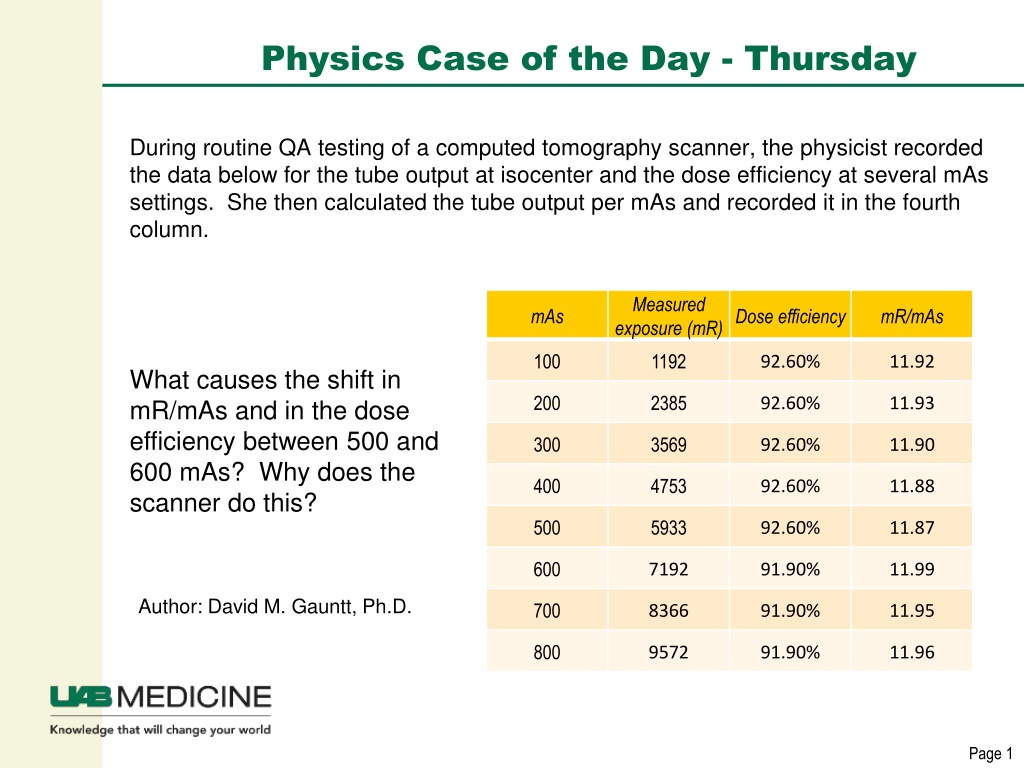
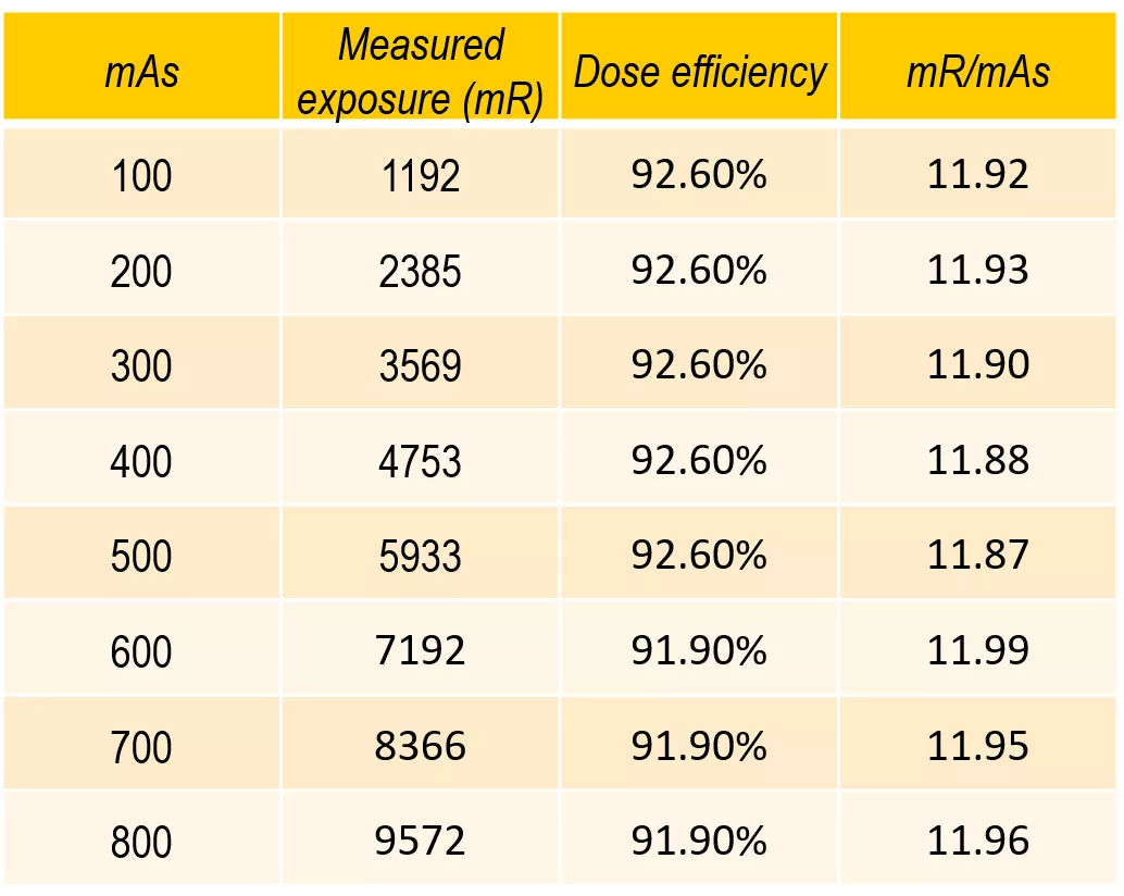
During routine QA testing of a computed tomography scanner, the physicist recorded
the data below for the tube output at isocenter and the dose efficiency at several mAs
settings. She then calculated the tube output per mAs and recorded it in the fourth
column.
What causes the shift in
mR/mAs and in the dose
efficiency between 500 and
600 mAs? Why does the
scanner do this?
Author: David M. Gauntt, Ph.D.

Physics Case of the Day - Thursday
During routine QA testing of a computed tomography scanner, the physicist measured
exposure at isocenter at 120kV for several mAs settings, and then recorded the data
below. She then calculated the tube output per mAs and recorded it in the fourth
column. Each measurement was fora single 1 second rotation of the gantry.
This model scanner uses the
small focal spot at 500 mA
and below, and the large focal
spot at 600 mA and above.
The collimator opens slightly
wider when using the large
focal spot than when using the
small focal spot; this is
reflected in the increased tube
output and decreased dose
efficiency.

Physics Case of the Day - Thursday
If the focal spot were infinitely
small, the collimator blades
could be set so only the active
rows of the detector array are
irradiated with primary x-rays.
In this case the system is
making the most efficient
possible use of the patient
dose, so the dose efficiency is
100%.
Physics Case of the Day - Thursday
In a real tube, the focal spot has a
non-zero size. As a result, part of the
detector array is irradiated by the
entire focal spot (the “umbra” of the
beam) and part is irradiated by only
part of the focal spot (the “penumbra”.
If the collimator width is set as if the
focal spot were infinitely small, part of
the active area of the detector would
be in the beam penumbra, and these
detector elements would have more
photon noise than those in the umbra.
Physics Case of the Day - Thursday
To ensure that the active area of the
detector is covered, the collimator
blades are moved apart slightly; this
increases the size of the umbra.
The dose efficiency is the fraction of
the primary x-rays that are travelling
toward the active area of the detector;
in this case, these are the x-rays in
the umbra.
Thus, the dose efficiency drops
slightly below 100%, and the
measured tube output increases
slightly.
Physics Case of the Day - Thursday
When the large focal spot is used, the
collimator is widened further to ensure that
the entire active area of the detector is
covered by the umbra.
The total tube output is increased, and the
dose efficiency is decreased, by the same
fractional amount as the increase in the
actual collimation width.
This effect is greater for narrower beam
widths; for 1.25mm widths often used in
high resolution chest, the dose efficiency
can drop below 50% because the
penumbra is wider than the active area of
the detector.
The physicist conducted testing on a computed tomography scanner to analyze the tube output and dose efficiency at various mAs settings. The shift in dose efficiency between 500 and 600 mAs is due to the use of different focal spots and collimator adjustments. When the collimator accommodates the larger focal spot, the dose efficiency decreases slightly. This adjustment aims to ensure optimal coverage of the detector's active area while balancing photon noise levels. By understanding these technical nuances, healthcare professionals can optimize imaging protocols for efficient and accurate diagnoses.

Uploaded on Oct 09, 2024 | 0 Views
Download Presentation

Please find below an Image/Link to download the presentation.
The content on the website is provided AS IS for your information and personal use only. It may not be sold, licensed, or shared on other websites without obtaining consent from the author.If you encounter any issues during the download, it is possible that the publisher has removed the file from their server.
You are allowed to download the files provided on this website for personal or commercial use, subject to the condition that they are used lawfully. All files are the property of their respective owners.
The content on the website is provided AS IS for your information and personal use only. It may not be sold, licensed, or shared on other websites without obtaining consent from the author.
E N D
Presentation Transcript
Physics Case of the Day - Thursday During routine QA testing of a computed tomography scanner, the physicist recorded the data below for the tube output at isocenter and the dose efficiency at several mAs settings. She then calculated the tube output per mAs and recorded it in the fourth column. Measured exposure (mR)Dose efficiency mAs mR/mAs 100 1192 92.60% 11.92 What causes the shift in mR/mAs and in the dose efficiency between 500 and 600 mAs? Why does the scanner do this? 200 2385 92.60% 11.93 300 3569 92.60% 11.90 400 4753 92.60% 11.88 500 5933 92.60% 11.87 600 7192 91.90% 11.99 Author: David M. Gauntt, Ph.D. 700 8366 91.90% 11.95 800 9572 91.90% 11.96 Page 1
Physics Case of the Day - Thursday During routine QA testing of a computed tomography scanner, the physicist measured exposure at isocenter at 120kV for several mAs settings, and then recorded the data below. She then calculated the tube output per mAs and recorded it in the fourth column. Each measurement was fora single 1 second rotation of the gantry. Measured exposure (mR)Dose efficiency This model scanner uses the small focal spot at 500 mA and below, and the large focal spot at 600 mA and above. mAs mR/mAs 100 1192 92.60% 11.92 200 2385 92.60% 11.93 300 3569 92.60% 11.90 The collimator opens slightly wider when using the large focal spot than when using the small focal spot; this is reflected in the increased tube output and decreased dose efficiency. 400 4753 92.60% 11.88 500 5933 92.60% 11.87 600 7192 91.90% 11.99 700 8366 91.90% 11.95 800 9572 91.90% 11.96 Page 2
Physics Case of the Day - Thursday If the focal spot were infinitely small, the collimator blades could be set so only the active rows of the detector array are irradiated with primary x-rays. In this case the system is making the most efficient possible use of the patient dose, so the dose efficiency is 100%. Page 3
Physics Case of the Day - Thursday In a real tube, the focal spot has a non-zero size. As a result, part of the detector array is irradiated by the entire focal spot (the umbra of the beam) and part is irradiated by only part of the focal spot (the penumbra . If the collimator width is set as if the focal spot were infinitely small, part of the active area of the detector would be in the beam penumbra, and these detector elements would have more photon noise than those in the umbra. Page 4
Physics Case of the Day - Thursday To ensure that the active area of the detector is covered, the collimator blades are moved apart slightly; this increases the size of the umbra. The dose efficiency is the fraction of the primary x-rays that are travelling toward the active area of the detector; in this case, these are the x-rays in the umbra. Thus, the dose efficiency drops slightly below 100%, and the measured tube output increases slightly. Page 5
Physics Case of the Day - Thursday When the large focal spot is used, the collimator is widened further to ensure that the entire active area of the detector is covered by the umbra. The total tube output is increased, and the dose efficiency is decreased, by the same fractional amount as the increase in the actual collimation width. This effect is greater for narrower beam widths; for 1.25mm widths often used in high resolution chest, the dose efficiency can drop below 50% because the penumbra is wider than the active area of the detector. Page 6