Data and Computer Communications
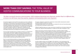
This content discusses wireless networks, WiMAX technology, and fixed broadband wireless access. It covers topics such as the advantages of fixed WBA, evaluating WBA against wired schemes and cellular technology, and the need for standards in BWA services. The content includes images illustrating fixed broadband wireless configurations and the implementation of wireless links, providing valuable insights into the world of wireless communication technologies.

Uploaded on Mar 06, 2025 | 0 Views
Download Presentation

Please find below an Image/Link to download the presentation.
The content on the website is provided AS IS for your information and personal use only. It may not be sold, licensed, or shared on other websites without obtaining consent from the author.If you encounter any issues during the download, it is possible that the publisher has removed the file from their server.
You are allowed to download the files provided on this website for personal or commercial use, subject to the condition that they are used lawfully. All files are the property of their respective owners.
The content on the website is provided AS IS for your information and personal use only. It may not be sold, licensed, or shared on other websites without obtaining consent from the author.
E N D
Presentation Transcript
Data and Computer Communications Tenth Edition by William Stallings Data and Computer Communications, Tenth Edition by William Stallings, (c) Pearson Education - 2013
CHAPTER 18 Wireless Networks
It was my old housekeeper who heard of it first by that strange wireless by which such people collect the news of the countryside. The Adventure of the Lion s Mane, by Sir Arthur Conan Doyle
Fixed Broadband Wireless Access Increasing interest is being shown in competing wireless technologies for subscriber access Approaches are referred to as wireless local loop (WLL) or fixed wireless access WiMAX Most prominent fixed broadband wireless access (fixed BWA) system Based on the IEEE 802.16 standard
Wireless links Base station antenna Residence Wire link Office building Switching center Government agency Figure 18.1 Fixed Broadband Wireless Configuration
Fixed WBA Advantages Cost Wireless systems are less expensive than wired systems Installation time Typically can be installed rapidly Key stumbling blocks: Obtaining permission to use a given frequency band Finding a suitable elevated site for the BS antennas Selective installation Radio units are installed only for those subscribers who want the service at a given time
Evaluating WBA WBA needs to be evaluated with respect to two alternatives: Wired scheme using existing installed cable Mobile cellular technology Lines not having a line of sufficient quality or are too far from the central office to effectively use xDSL 4G cellular systems provide broadband support Cable two-way data services not offered by cable provider Fixed WBA BS can cover a larger area WLL has become cost-competitive with wired schemes Higher data rates can be achieved
WiMAX/IEEE 802.16 Need within the industry to develop standards for BWA services 802.16 working group was set up in 1999 to develop broadband wireless standards WiMAX (Worldwide Interoperability for Microwave Access) Forum Formed to promote 802.16 standards and to develop interoperability specifications Charter for the group was to develop standards that: Use wireless links with microwave or millimeter wave radios Use licensed spectrum (typically) Are metropolitan in scale Provide public network service to fee- paying customers (typically) Use point-to-multipoint architecture with stationary rooftop or tower-mounted antennas Provide efficient transport of heterogeneous traffic supporting quality of service (QoS) Are capable of broadband transmissions (>2 Mbps)
Fixed WiMAX modem Laptop Tablet Cell Phone Access Service Network (ASN) Access Service Network (ASN) Network Access Provider (NAP) Base stations Base stations ASN Gateway ASN Gateway Network Service Provider (NSP) CSN server CSN server Connectivity Service Network (CSN) Connectivity Service Network (CSN) Internet Figure 18.2 Elements of the WiMAX Network Reference Model
IPv4 IPv6 IPv4 IPv6 Ethernet Ethernet ATM Service-Specific Convergence Sublayer IEEE 802.16 Layers MAC Common Part Sublayer Security Sublayer Physical Layer Figure 18.3 IEEE 802.16 Protocol Architecture
Protocol Architecture MAC layer is divided into three sublayers: Physical layer Encoding/decoding of signals Preamble generation/removal (for synchronization) Bit transmission/receptio n Frequency band and bandwidth allocation Service-specific convergence sublayer Security sublayer Common part sublayer On transmission, assemble data into a protocol data unit (PDU) with address and error detection fields Encapsulate PDU framing of upper layers into the native 802.16 MAC PDUs Includes authentication, secure key exchange, and encryption On reception, disassemble PDU, and perform address recognition and error detection Concerned with secure communication between the SS and the ASN base station Map an upper layer s addresses into 802.16 addresses Govern access to the wireless transmission medium Translate upper layer QoS parameters into native 802.16 format Adapt the time dependencies of the upper layer traffic into the equivalent MAC service Responsible for sharing access to the radio channel
IEEE 802.16 MAC Layer Connection oriented Each MAC PDU includes a connection ID which is used by the MAC protocol to deliver incoming data to the correct MAC user There is a one-to-one correspondence between a connection ID and service flow Service flow defines the QoS parameters for the PDUs that are exchanged on the connection Examples of service flow parameters are latency, jitter, and throughput
Scheduling Service and QoS Maximum sustained traffic rate The peak information rate, in bits per second of the service Rate pertains to the service data units at the input to the system Parameter is 6 bits in length and includes values in the range from 1200 bps to 1.921 Mbps Minimum reserved traffic rate The minimum rate, in bits per second, reserved for this service flow The BS shall be able to satisfy bandwidth requests for a connection up to its minimum reserved traffic rate Values range from 1200 bps to 1.921 Mbps The maximum interval between the reception of a packet at the convergence sublayer of the BS or the SS and the forwarding of the SDU to its air interface Values range from 1 ms to 10 s Maximum latency Tolerated jitter The maximum delay variation (jitter) for the connection Values range from 1 ms to 10 s The priority of the associated service flow The higher-priority service flow should be given lower delay and higher buffering preference For otherwise nonidentical service flows, the priority parameter should not take precedence over any conflicting service flow QoS parameter Eight priority levels are used Traffic priority
Table 18.1 IEEE 802.16 Service Classes and QoS Parameters Scheduling Service (uplink) Unsolicited grant service (UGS) Data Delivery Service (downlink) Unsolicited grant service (UGS) Applications QoS Parameters VoIP Minimum reserved traffic rate Maximum latency Tolerated jitter Minimum reserved traffic rate Maximum sustained traffic rate Maximum latency Traffic priority Minimum reserved traffic rate Maximum sustained traffic rate Traffic priority Maximum sustained traffic rate Traffic priority Minimum reserved traffic rate Maximum sustained traffic rate Maximum latency Tolerted jitter Traffic priority Real-time polling service (rtPS) Real-time variable-rate service (RT-VR) Streaming audio or video Non-real-time polling service (nrtPS) Non-real-time variable-rate service (NRT-VR) FTP Best effort service (BE) Best effort service (BE) Data transfer, Web browsing, etc. Extended rtPS Extended real-time variable-rate service (ERT-VR) VoIP (voice with activity detection)
Fixed packet size Fixed packet size Fixed packet size Fixed packet size (a) Unsolicited grant service time uniform periodic intervals unicast polls Data Data Data Data (b) Real-time polling service time uniform periodic intervals unicast polls (c) Non-real-time polling service Data Data Data Data time variable interval size (d) Best effort service Data Data Data Data time non-deterministic time intervals Figure 18.5 IEEE 802.16 Services
Table 18.2 IEEE 801.16 Physical Layer Modes WirelessMAN-SC WirelessMAN-OFDM WirelessMAN-OFDMA Frequency band 10 to 66 GHz 11 GHz 11 GHz LOS limitation LOS NLOS NLOS Duplexing technique TDD, FDD TDD, FDD TDD, FDD Uplink access TDMA, DAMA OFDM OFDMA Downlink access TDM, TDMA OFDM OFDMA Downlink modulation QPSK, 16-QAM, 64- QAM QPSK, 16-QAM, 64- QAM, BPSK QPSK, 16-QAM, 64- QAM, BPSK Uplink modulation QPSK, 16-QAM, 64- QAM QPSK, 16-QAM, 64- QAM, BPSK QPSK, 16-QAM, 64- QAM, BPSK Channel size 20 to 28 MHz 1.75 TO 20 MHZ 1.25 TO 20 MHZ Subcarrier spacing N/A 11.16 kHz 11.16 kHz Data rate 32 to 134 Mbps 70 Mbps 70 Mbps Downlink FEC Reed-Solomon Reed-Solomon Convolutional Uplink FEC Reed-Solomon Reed-Solomon Convolutional
Table 18.3 Data Rates Achieved at Various WirelessMAN-OFDM Bandwidths QPSK QPSK 16-QAM 16-QAM 64-QAM 64-QAM Modulation 1/2 3/4 1/2 3/4 2/3 3/4 Code Rate 1.75 MHz 1.04 2.18 2.91 4.36 5.94 6.55 3.5 MHz 2.08 4.37 5.82 8.73 11.88 13.09 7.0 MHz 4.15 8.73 11.64 17.45 23.75 26.18 10.0 MHz 8.31 12.47 16.63 24.94 33.25 37.40 20.0 MHz 16.62 24.94 33.25 49.87 66.49 74.81
Time gap Downlink subframe Uplink subframe Ranging subchannel FCH (carrying the UL MAP) UL burst #1 DL burst #3 DL burst #1 Frequency (subchanels) UL burst #2 Preamble DL burst #4 DL-MAP UL burst #3 DL burst #5 UL burst #4 DL burst #2 DL burst #6 UL burst #5 Time Figure 18.6 IEEE 802.16 OFDMA Frame Structure in TDD Mode
Time OFDMA frame duration DL subframe 1 DL subframe 2 next frame Preamble Preamble MAP1 MAP1 MAP1 DL1 DL2 Frequency TTG2 TTG1 RTG2 RTG1 UL2 UL1 UL subframe 2 UL subframe 1 TTG = transmitter-to-receiver gap RTG = receiver-to-transmitter gap Figure 18.7 IEEE 802.16 OFDMA Frame Structure in FDD Mode
Bluetooth Overview An always-on, short-range radio hookup that resides on a microchip Concept behind Bluetooth is to provide a universal short- range wireless capability Intended to support an open-ended list of applications Bluetooth capabilities: Make calls from a wireless headset connected remotely to a cell phone Eliminate cables linking computers to printers, keyboards, and the mouse Hook up MP3 players wirelessly to other machines to download music Set up home networks so that a couch potato can remotely monitor air-conditioning, the oven, and children s Internet surfing Call home from a remote location to turn appliances on and off, set the alarm, and monitor activity
vCard/vCal OBEX WAE WAP AT = Core protocols SDP TCS BIN commands = Cable replacement protocol = Telephony control protocols UDP/TCP IP PPP = Adopted protocols Audio RFCOMM Control Logical Link Control and Adaptation Protocol (L2CAP) Host-controller interface Link Manager Protocol (LMP) Baseband Bluetooth Radio AT IP OBEX PPP RFCOMM = radio frequency communications SDP = service discovery protocol TCP = transmission control protocol = attention sequence (modem prefix) = Internet Protocol = Object exchange protocol = Point-to-Point Protocol TCS BIN = telephony control specification - binary UDP = User Datagram Protocol vCal = virtual calendar vCard = virtual card WAE = wireless application environment WAP = wireless application protocol Figure 18.8 Bluetooth Protocol Stack
Adopted Protocols PPP The point-to-point protocol is an Internet standard protocol for transporting IP datagrams over a point-to- point link TCP/U DP/IP These are the foundation protocols of the TCP/IP OBEX The object exchange protocol is a session-level protocol developed by the Infrared Data Association WAE/W AP Bluetooth incorporates the wireless application environment and the wireless application
Piconets A small network in which up to eight devices can communicate Consists of a master and from one to seven active slave devices The radio designated as the master makes the determination of the channel and phase that shall be used by all devices on the piconet A slave may only communicate with the master and may only communicate when granted permission by the master Ten of these piconets can coexist in the same coverage of the Bluetooth radio To provide security each link is encoded and protected against eavesdropping and interference
M S S S M/S S S S S Figure 18.9 Master/Slave Relationships
(a) Cellular system (squares represent stationary base stations) (b) Conventional ad hoc systems (c) Scatternets Figure 18.10 Wireless Network Configurations
Table 18.4 Bluetooth Radio and Baseband Parameters Topology Up to 7 simultaneous links in a logical star Modulation GFSK Peak data rate 1 Mbps RF bandwidth 220 kHz ( 3 dB), 1 MHz ( 20 dB) RF band 2.4 GHz, ISM band RF carriers 23/79 Carrier spacing 1 MHz Transmit power 0.1 W Piconet access FH-TDD-TDMA Frequency hop rate 1600 hops/s Scatternet access FH-CDMA
Frequency Hopping (FH) In Bluetooth serves two purposes: It provides resistance to interference and multipath effects It provides a form of multiple access among co-located devices in different piconets
f(k) f(k + 1) f(k + 2) master t slave t 625 s Access code Header Payload Figure 18.11 Frequency-Hop Time-Division Duplex
Physical Links Two types of links can be established between a master and a slave: Synchronous connection oriented (SCO) Asynchronous connectionless (ACL) Allocates a fixed bandwidth between a point-to-point connection involving the master and a single slave The master maintains the SCO link by using reserved slots at regular intervals The master can support up to three simultaneous SCO links, while a slave can support two or three SCO links Are never retransmitted A point-to-multipoint link between the master and all the slaves in the piconet In slots not reserved for SCO links, the master can exchange packets with any slave on a per-slot basis SCO links are used primarily to exchange time-bounded data requiring guaranteed data rate but without guaranteed delivery ACL links provide a packet-switched style of connection
bits 72 54 0 to 2745 Access Code Header Payload (a) Packet format 3 4 1 1 1 8 AM_Addr Type Flow Header error control (HEC) ARQN SEQN (b) Header format (prior to coding) 2 1 5 L_CH Flow Length Single-slot packets 2 1 9 4 L_CH Flow Length Undefined Multislot packets (c) Data payload header format Figure 18.12 Bluetooth Baseband Formats
Error Correction At the baseband level Bluetooth makes use of three error correction schemes: 1/3 rate FEC (forward error correction) Used on the 18-bit packet header and also for the voice field in an HV1 packet Scheme involves sending three copies of each bit 2/3 rate FEC Used in all DM packets In the data field of the DV packet, in the FHS packet, and in the HV2 packet Code can correct all single errors and detects double errors in each codeword ARQ (automatic repeat request) Used with DM and DH packets, and the data field of DV packets Scheme similar to ARQ schemes used in data link control protocols
f(k+1) f(k+2) f(k+3) f(k+4) f(k+5) f(k+6) f(k+7) f(k+8) f(k+9) f(k+10) f(k+11) f(k+12) A B B X C Master t ACK ACK NAK Failure ACK NAK ACK ACK Failure F G H Slave 1 t ACK Z Z Slave 2 t 625 s Figure 18.13 An Example of Retransmission Operation
Logical Channels Bluetooth defines five types of logical data channels designated to carry different types of payload traffic: Used to manage the flow of packets over the link interface Carries low level link control information like ARQ, flow control, and payload characterization Carried in every packet except in the ID packet which has no packet header Link control (LC) Link manager (LM) Transports link management information between participating stations Supports LMP traffic and can be carried over either an SCO or an ACL link User asynchronous (UA) Carries asynchronous user data Carried over the ACL link but may be carried in a DV packet on the SCO link User isochronous (UI) Carries isochronous user data Carried over the ACL link but may be carried in a DV packet on the SCO link User synchronous (US) Carries synchronous user data Carried over the SCO link
0 0 0 1 1 1 1 1 1 0 1 0 0 0 0 0 1 0 1 1 1 1 0 0 1 1 1 1 0 1 0 1 0 1 0 0 0 0 0 0 1 1 0 1 1 1 1 0 0 Figure 18.14 Example of Continuously Variable Slope Delta Modulation
Table 18.5 CVSD Parameter Values Parameter Value 1-1 h 32= 0.96875 b 1 1- 1024 0.999 J 4 K dmin dmax 4 10 1280 ymin 215 or 215 +1 ymax 215 1
Bluetooth Logical Link Control and Adaptation Protocol L2CAP provides: A link-layer protocol between entities across a shared-medium network A number of services and relies on a lower layer for flow and error control Two alternative services to upper-layer protocols: Connectionless service This is a reliable datagram style of service Connection-mode service A logical connection is set up between two users exchanging data, and flow control and error control are provided
L2CAP Logical Channels Connectionless Supports the connectionless service Each channel is unidirectional Typically used for broadcast from the master to multiple slaves Connection oriented Supports the connection-oriented service Each channel is bidirectional (full duplex) A QOS flow specification is assigned in each direction Signaling Provides for the exchange of signaling messages between L2CAP entities Associated with each logical channel is a channel identifier (CID)
Flow Specification Set of parameters that indicate a performance level that the transmitter will attempt to achieve Consists of the following parameters: Service type Token rate (bytes/second) Token bucket size (bytes) Peak bandwidth (bytes/second) Latency (microseconds) Delay variation (microseconds)
Summary Bluetooth radio specification Bluetooth baseband specification Frequency hopping Physical links Packets Error correction Logical channels Bluetooth audio Bluetooth logical link control and adaption protocol Fixed broadband wireless access WiMAX/IEEE 802.16 802.16 architecture 802.16 MAC layer 802.16 physical layer Bluetooth overview Protocol architecture Piconets and scatternets


 Cellular system (squares represent")

")
")


")