Concrete Handling in Field: Essential Techniques and Equipment


Department of Civil Engineering
1
Concrete Handling in Field
By:
Nishant Singh Kushwaha


Concrete Handling in field
T
h
i
s
P
o
w
e
r
p
o
i
n
t
p
r
e
s
e
n
t
a
t
i
o
n
c
o
v
e
r
s
e
n
t
i
r
e
u
n
i
t
o
f
C
o
n
c
r
e
t
e
h
a
n
d
l
i
n
g
i
n
f
i
e
l
d
.
Most of the material covers in this ppt and
rest if left please refer to
M.S Shetty book.
Stages of producing
concrete.
3
(1)
Batching
(2)
Mixing
(3)
Transportation
(4)
Placing
(5)
Compacting
(6)
Curing
(7)
Finishing
(1)
Batching
4
(a)
Volume
batching
(b)
weight
Baching
Volume
batching
5
Volume batching
is
not good
method
Moist
sand in
loose condition weights
less
than the
same
volume
of
dry
sand.
Practiced for small
work.
For
quality
work
,weigh batching
is
practiced.
VOLUME
BATCH
Gauge
box
Various gauge boxes of
different
volumes are
used.
6
Weigh Batch
Machine
7
Weigh
batching
8
Weigh batching is correct
method
Facilitates accuracy,
flexibility
&
simplicity
Different batching machine are available
:
(a)
manual machines & (b) Automatic
machines
Manual machine
:
Has two
buckets
Buckets mounted on common spindle about which they
rotate.
One is loaded while
other
is discharged in
mixer.
Spring loaded dials indicate the
weight.
Automatic weigh
batch
9
For
large
works
Over
head hopper and
discharges
into
mixer.
Useful in
ready
mix concrete
plant
Recorders for
weight
Calibration
is
required
from
time
to
time.
(2)
MIXING
10
Mixing
of cement,sand aggregates
should
ensure
that:
The
mass
is
homogeneous
Uniform
in
color
consistent
MIXING METHODS
:
(1)
Hand
mixing
(2)
Machine
mixing
11
Hand
mixing
Practiced
for small
scale work
(small
house,
repairing
of
house
etc)
10 % extra cement is
added to
compensate inferior
concrete
produced
by
this method.
Spread
fine
& coarse
aggregate
in
alternate
layer
Spread cement over
it
Mix with shovel till
uniform color
is
achieved
Machine
mixing
13
Medium
&
large
scale work use
machine
mixing
Mixing
is
efficient, economical
&
produce
quality concrete.
Type of
mixer:
(a)
Batch mixer :
batch
by
batch
with
time
interval
(b)
Continuous mixer: continuously
mixed
&
discharged (in
dam
construction)
CONCRETE
MIXER
14
(1)
Pan
type
(2)
drum
Type:
(a)
tilting
(b)
Non
–tilting
(c)
Reversing
PAN
MIXER
15
PAN
MIXER
16
A
forced movement pan mixer has blades
that are
fixed to an assembly
that
agitates
the concrete
throughout
the
pan
as
the
vertical shaft
rotates.
DRUM
MIXER
17
As
per
IS:
1791-1985
mixers are
designated
by
number
which
shows
capacity
(liters)
of
batch:
a)
Tilting
:
85
T, 100T, 140
T,
200T
b)
Non
tilting
: 200 NT,280 NT,
375
NT,
500
NT,
1000
R
c)
Reversing :
200
R,
280
R,
375 R,500
R,
1000
R
T=
Tilting,
NT
=non tilting,
R=Reversing
TILTING
MIXER
18
TILTING
MIXER
19
Internal blades lift and tumble the
ingredients onto
itself.
Two
primary
types
exist:
horizontal (one end has and opening
for
charging and
a
different end for
discharging)
single drum (materials
are
charged
and
discharged
through
a
single
opening).
NON TILTING
MIXER
20
NON TILTING
MIXER
21
Single drum rotating about
a
horizontal
axis.
Fixed
blades work the
concrete towards
the
discharge end
of
the mixer, in
order
to
provide a
rapid
rate of
discharge.
REVERSING
MIXER
22
REVERSING
MIXER
23
The entire
drum rotates
around its
axis
as
materials are
loaded through
a
charge chute
at
one
end
of the drum and exit through a
discharge chute
at the
opposite
end
of
the
drum.
Mixing blades
are mounted
on the
inside surface
of the drum and
as
the drum rotates the blades
mix by lifting and
dropping
the materials
during
each
rotation.
Once the
materials
are
sufficiently
mixed the
rotation of
the drum is reversed
and
the blade
arrangement pushes the concrete through to the
discharge end
of the mixer.
Sequence of charging
drum
24
First
half quantity
of coarse
aggregate
is
placed
in
skip
Over it
half quantity of
sand
On
that full quantity
of
cement
Over it
balance quantity
of coarse &
fine
aggregates
is
place.
This prevents spillage
of
cement
in
air
while
discharging
in
drum
25
%
Water
is placed in drum
and
then
mix
from
skip is discharged in the
drum
This prevents
sticking of cement on
blades
75
water
is
immediately poured after
placing
mix
material (cement
sand etc)
in
drum.
25
25
Mixing
time
In
small machine,
mixing time
varies
between 1-2
minutes
In
Ready Mix Cement
mixer –
15-30
seconds
RPM
of
drum
:
15-20
Compressive
strength
of concrete
increases with
increase
in
mixing time
but
after
2
minutes increase
in compressive
stre
n
g
t
h
is n
o
t si
g
n
K
i
A
f
S
i
-
2
c
0
1
a
2
n
t.
26
If
concrete
is
not used after mixing
it
may
set
But when concrete is
agitated
on
time
to
time
in
drum setting time rule does not
follow.
27
Retempering of concrete
:
Some time
concrete from RMC
plant is
not
delivered
to site
due
to traffic
congestion
Concrete
becomes
stiff
and
becomes
unworkable
Site
engineers
can
reject
the concrete
if
delay
is
more
If it can be
of used
then
small
volume
of
water
is
added and again agitated
in
the
drum. This
is
called RETEMPERING
OF
CONCRETE.
MANUFACTURING
OF
29
CONCRETE
With same
material if
care is
not
taken,
resulting concrete will be
bad
concrete
What are good rules
to
make good
quality
concrete.
TRANSPORTATION OF
CONCRETE
30
Precaution
in concrete
transportation:
Homogeneity
of conc.
Mass
is
maintained
Movement
of
hand trolly
or truck on
rough
road
surface makes
vibrations
This results
in
deposition
of
heavy
aggregates
at bottom
of
truck
Water
&
cement
slurry comes
on
top.
METHODS OF
TRANSPORTATION
31
1.
Mortar
Pan
2.
Wheel
barrow
3.
Truck
Mixer
&
dumpers
4.
Crane, Bucket
&
rope
way
5.
Belt conveyors
6.
Chutes
7.
Skip
&
hoist
8.
Transit
Mixer
9.
Pump
&
pipeline
10.
Helicopter
MORTAR
PAN
32
Common method
in
India
More labour
required
Segregation
of concrete is
less
Greater
surface
area
of concrete
is
exposed to sun, concrete
dries.
WHEEL
BARROW
33
When transportation
of concrete is
at
ground
level.
Movement
of
wheel
on
rough
road
surface,
segregates
concrete.
Some wheel barrows have
pneumatic
wheel
to
reduce
vibration
CRANE
34
Used
for transporting
concrete
above
ground
level.
For
high rise
buildings.
Cranes
are
fast
Can
move horizontally
&
vertically
Concrete in skip discharge from
bottom
In bucket concrete is discharged by
tilting.
BUCKET &
ROPEWAY
35
Use
for
construction
in:
Valley
Bridge pier
in
river
Dam
Adva
n
ta
g
e:
Concrete is
not exposed
to sun or
air
&
no
loss of
water.
Truck Mixer &
dumpers
36
Used
for
large concrete
works.
Can travel
any part
of
site.
Dumpers
-
2-3
M
3
Capacity
Trucks – 4 M
3
Capacity
Bottom
surface of truck is kept
wet
Top of
truck
is covered to
prevent
evaporation
BELT
CONVEYORS
37
Limited use in
construction
Advantages:
Can transport large
volume
Very
quick
Can go where access is
limited
Disadvantages
:
On steep slope concrete
segregates.
Exposed to sun for long
time.
CHUTE
38
For transporting
from
ground
level
to
lower
level. (basement
etc).
Used where
labour
can
not reach due
to
less space in
trench
etc.
Made
of
metal
Slope should not
be < 1 vertical :
2.5
horizontal.
SKIP &
HOIST
39
Labour
can go
upto
3rd or
4th
floors.
So skip is used for transport vertically
up
(in
multistory
building).
Skip
travels
on vertical
rail.
Skip can
discharge manually
or
automatically.
TRANSIT
MIXER
40
TRANSIT
MIXER
41
Used for
long distance travel
in RMC
plant.
Concrete is
continuously
agitated in
truck
drum
(2 – 6
rpm).
Also
transported
mix
in dry condition and
water
is added on
reaching
the
destination.
Wet Mix in
truck
must
reach site
in
1-
1.5 hours.
Pumps are
also fitted
on
truck mixer
to
discharge
concrete.
PUMPS &
PIPELINE
42
Most popular
method
Reliable & good quality pumps are
used.
Mostly operated by
diesel.
Concrete is placed in
collecting
hopper.
Rotating
blades
in hopper pushes concrete
towards
pipe.
Vacume in
hose
pipe
(600
mm
Hg)
Rotating
rollers
in pump chambers squeeze the
concrete in pipe and
flow
of concrete is
started.
Concrete is discharged from other
end of
hose
pipe.
Concrete can be pumped upto 400 m height and
2000 m
distance.
SECTION
OF
PUMP
43
PIP
E
LINE
44
Pipeline
should
:
Have correct
diameter
as
per
pump
pressure.
(generally 125
mm)
Have sufficient
thickness
Good
couplings
Poor pipeline
can cause
blockage.
44
PIPELINE
Thumb
rule :
For
30
M
3
/hr concrete
and
200
m
length, dia
should be
100
mm.
Length
>
500
m
then dia
=
150
mm.
Dia = 3
to
4
times
the size of
aggregate
Leaky pipe &
coupling result
in escape
of
water /air
&
finally block the
concrete.
Vertical pipe
should
good
otherwise
difficult
to
change
at
height.
Pump
is
kept at
distance from
building
about 15
%
of vertical
length.
KAS-2012
PUMPABLE
CONCRETE
46
Concrete which
can be
pushed
through a
pipeline
is
called pumpable
concrete.
Friction
between pipe wall and concrete is
less.
Concrete flows in
the form of
plug
which is separated
from
pipe wall by a thin layer
of
lubricating
cement
paste.
Flow
resistant must
be
<
pump
pressure.
If the
concrete is
more
wet then water
comes out of
mix
which
makes more
resistance
to
flow.
Stiff
and also
very wet
concrete is
not
pumpable.
Design of pumpable
concrete
47
Concrete
Mix is so
designed
that
all
material
remain
together.
Mix
must
make redial
movement of
grout to maintain
lubricating
paste.
Mix should be deformed
at
bends
Cement & fine particles (0.25
mm
size) are
important for
good
flow.
350
to
400 Kg/
M
3
of fine
particles
are
necessary
for
flow.
Slump
of
pumpable concrete is above 75
mm.
PROBLEMS IN
PUMPING
48
Blockage in
pipe
Pipe should
be
cleaned after each
day
operation
Blockage
can be
cleaned
by
forward-
backward
pumping.
Tapping
pipe with
hammer
Clean pipe
with rod or
sponge ball
pushed
by compressed
air.
PLACING
CONCRETE
49
Must
be
placed
in systematic
manner.
Can be
placed
with
following
methods:
Within earth mould
:
Foundation
In
timber plank
formwork :
Road,
airport
slab.
Steel shuttering
:
Dam
Under
water
Concrete in
Foundation
50
In
foundation, ground
is made
wet.
Plastic sheet are laid between ground
&
slab
Concrete is dumped
not
poured.
No heap and
dragging
Placed in layers
of
35
–
40
cm
in
mass
concrete
Avoid cold joints between 2
layers
Surface
of
previous layer is cleaned with wire
brush
Sometime,
cement slurry
is
placed
on old
surface
Top of
previous layer
kept
rough
for
good
bond.
Concrete on Road, airport, floor
slabs
Placed in
alternate bays (allow
shrinkage)
with contraction
joints
:
contraction
joints
Bays
51
Concrete in Beams &
Column
52
Reinforcement
correctly
placed.
Correct cover
required
Joints
of
shuttering
to be
plugged.
Mould releasing agent inside
formwork
STRIPPING
TIME
53
Form work should
not
removed until good
strength
has
come.
UNDER WATER
CONCRETE
54
UNDER WATER
CONCRETE
55
Tremie (means hopper)
is
used.
Funnel
on
top
Pipe
of
200
mm
size
Pipe bottom
is
plugged
Fill pipe with
concrete
Lift
pipe
or jerk
to
release the
plug
Keep bottom
of
pipe inside
concrete
Underwater
Concrete
56
No
compaction required
as
hydrostatic
pr
of
water
compacts
concrete.
Concrete of 0.3 W/C
ratio
can be
placed
with
Tremie.
Used for Pile or well
foundation
SLIP FORM
TECHNIQUE
57
2
In
this method, concrete
is
continuously
placed,
compacted
& form
work
is
pulled up
for
next layer
of
concrete.
Vertical slip
form for
Tall
structure
like silo,
chimney
Horizontal slip
form
paver machine
(HSFP) for
road
construction.
Concrete is dumped in front of
HSFP
machine by
dumpers.
Compaction by vibrator installed inside HSFP
machines.
Finishing
of
surface by
HSF
paver.
Operation
of
road alignment, gradient, curve are controlled by
Computerized Laser Control
system.
Speed
of
construction is 1
mt
/min.
1 km of
concrete road of 3.75
mt
width
is
built
in
one
day (16
hrs
work).
Mumbai-Pune
Expressway
was
constructed by
this
machine.
VERTICAL SLIP
FORM
58
HORIZONTAL SLIP FORM ROAD
PAVER
59
COMPACTION OF
CONCRETE
60
Compaction is a process of expelling the entrapped air
inside
concrete
mass.
During mixing, transporting & placing the concrete, air gets
trapped
in concrete
mass.
If this air is not removed, concrete will not get
strength.
5 % of air voids reduces strength by 30
%
10 % of air voids reduces strength by 50
%
Durability of concrete is also reduces with air
voids.
Insufficient compaction increases permeability of
concrete.
Results in entry of aggressive chemicals in
solution.
Chemicals attack concrete & reinforcement and
life
of
concrete
is
reduced.
METHODS OF
COMPACTION
61
1.
Hand
compaction
2.
Compaction by
vibration
3.
Compaction by pressure
&
jolting
4.
Compaction by
spinning
(2)
COMPACTION BY
VIBRATION
62
a)
Internal
Vibrator
b)
Formwork
Vibrator
c)
Table
Vibrator
d)
Platform
Vibrator
e)
Surface
Vibrator
(1)
HAND
COMPACTION
63
Hand
Rodding
Poking inside concrete with
1-2
mt long
steel
rod
Ramming
Unreinforced
foundation & ground floor
work
Tamping
Wooden beam is
used
to
beat concrete
(low
thickness
slab,
road
slab)
COMPACTION BY
VIBRATION
64
In
hand compaction
w/c ratio is
more
so
we
get
less
strength
in
concrete.
In
mechanical
vibrator w/c can be kept
low
so we
get good
strength.
INTERNAL
VIBRATOR
65
(a) INTERNAL
VIBRATOR
66
Most common in
use
Called, Needle Vibrator
or Immersion vibrator or
Poker
vibrator.
Consists : electrical/diesel
power
supply,
Needle
and
shaft.
Frequency of
vibrations
can be
12000
cycles
vibration per minute.
Needle diameter 20 to 75
mm
Length 25 to 90
cm.
Portable.
FORMWORK
VIBRATOR
67
Used
for columns, walls,
precast
slab
Vibrator
is
clamped
to
formwork
Vibration
is
given
to
formwork
Vibration
is
transferred
from formwork
to
concrete
Useful in
thin
wall where
reinforcement
obstruct the
needle
type
vibrator.
Efficiency is
lower then needle
vibrator
TABLE
VIBRATOR
68
Vibrator
is
clamped
to
table
Used for concrete test
cubes
Cubes are
kept on
table
to
get
vibrations
Also
used
for small
prefabricated
slab
TABLE
VIBRATOR
69
PLATFORM
VIBRATOR
70
Similar
to
table vibrator but of
large
size
Used for
long concrete electrical
pole,
railway
sleeper,prefabricated roofing
element
PLATEFORM
VIBRATOR
71
SURFACE
VIBRATOR
72
Known
as
Screed
Board
Vibrator
Used for
thin roof
slab where
needle
vibrator can
not
be
used
Not
effective
if
slab
thickness is
more
then
15
cm.
SURFACE
VIBRATOR
73
COMPACTION BY PRESSURE &
JOLTING
Used
for hollow
blocks, solid
concrete
blocks
Stiff
concrete is
vibrated,
pressed &
given
jolts
Stiff
concrete is compacted to
get
dense
form &
good strength
is
achived.
74
VIBRATION BY
SPINNING
75
New
method
Used for concrete
pipes
Concrete when spun at
high
speed
gets
compaction
by
centrifugal
force
VIBRATORY
ROLLER
76
Road rollers has vibrating
system
Roller while moving
on
raod
slab
gives
vibrations
Used for
Lean
concrete
(M10)
for
road
base
ROLLER
VIBRATOR
77
PRECAUTIONS
IN VIBRATING
CONCRETE
Vibrator gets damaged
if
comes
in
contact
with
hard object (Formwork, hard
concrete)
Switch on
when needle
is inside
fresh
concrete
mass
Should
conform to IS
2505-1963
Degree of compaction can be
recognized
from rising
air bubbles
&
formation
of
thin
film on
top
78
HYDRATION OF
CEMENT
79
Cement
is made by
Cao, SiO
2
, Al2O
3
, Fe
2
O
3
,
MgO,
K
2
O,
SO
3
After
burning in Kiln following products are
made:
- Tri
calcium
silicate
–
Di cacium
silicate
3Cao. SiO
2
(C
3
S)
2Cao.
SiO
2
(C
2
S)
3Cao. Al
2
O
3
(C
3
A)
– Tri
cacium
aluminate
4Cao. Al
2
O
3
. Fe
2
O
3
(C
3
AF) -Tricalcium alumino
ferrite.
On
addition
of
water
in
cement
reaction
of
C
3
S, C
2
S, C
3
A
&
C
3
AF liberate heat. Heat is suside by addition
of
water.
CURING OF
CONCRETE
80
Curing
is
defined
as
“
making
satisfactory
moisture
content &
favourable
temperature”
in concrete
after
placing
the concrete.
So
that
hydration
may
continue
until
the
strength
is
developed.
Curing
is
required immediately
after
placing
concrete.
During hydration, heat
of
hydration is
released.
CURING OF
CONCRETE
81
Concrete delivers
its strength by the
hydration
of
cement
particles.
Hydration is continuous
&
long
time
process.
Rate
of
hydration is
fast
immediately
after
making
the
concrete
Theoretically 0.23
w/c ratio
required
for
hydration
0.15
w/c
ratio required
for
filling
the
voids in
gel.
Total
0.38
w/c
ratio is optimum
In
field condition, water evaporates
&
available water
quantity reduced
for
hydration
Extra water is given by
curing
METHODS OF
CURING
82
a)
Water curing
b)
Membrane
curing
c)
Application of
heat
d)
Other
methods
WATER
CURING
83
a)
Immersion
:
Slab is
kept
in water
tank
b)
Ponding:
Roof slab is
filled
with
water
c)
Spraying
:
water
spary
on
concrete
wall
is
d)
Wet covering :
Wet gunny bags on
wall
MEMBRANE
CURING
84
Concrete surface is covered by
plastic
membrane
It
is
used where
water availability
is
less.
Plastic
sheet
reduces
evaporation
in
concrete
Membrane
is
applied after
2
days
of
water
curing
APPLICATION OF
HEAT
85
Spraying
of steam on concrete
provides heat
&
moisture.
Higher temperature accelerates hydration
rate &
strength
of
concrete is
attended
Early
strength of structure
is
obtained
Steam
application possible
at precast factory
only.
Precast
prestressed concrete girders
of
bridge are cured
with
steam
Fast
construction of
bridge
HIGH PRESSURE STEAM
CURING
86
Superheated
steam at
high pressure
(8.5
kg/cm2)
&
high
temperature(175 deg C) is applied on
concrete.
This process is called
“Autoclaving”
28 days strength of concrete is achieved in one
day
Concrete becomes sulphate
resistant
Low shrinkage in
concrete
Used in production
of
Cellular
concrete
products(
Siporex,
Celcrete)
FINISHING OF
CONCRETE
87
Finishing
is
last operation
of
concrete
making.
Finishing
of top
surface is required in roads, airport
strip, home
floor
Methods
of
Finishing:
a)
Form
work
Finish
b)
Surface
Treatment
c)
Applied
Finishes
FORMWORK
FINISH
Concrete obeys
the shape
of
formwork
Grooves &
lining
on formwork
plate
gives
makes grooves &
lining
on
concrete
Prefabricated tiles
can be
made
of
any
design
SURFACE
TREATMENT
88
Domestic floor should
be smooth,
wear
resistant,
crack
free.
Mix
should have good proportion without excess
“Matrix”
Exposed aggregate finish
:
Colored pebbles on
top
layer
of
wall
Bush Hammering
:
Electrically operated Brush with
teeth
when applied on concrete
removes top cement
layer,
exposes aggregates and
makes
shining
aggregates.
APPLIED
FINISH
Rough cast
finish
:
mixture
of
cement, sand,
round
gravel is applied on
wall
Non slip
finish:
Railway platform
&
walkway
around
pool are given non slippery finish by
mixing
large size
sand particles
in
floor
concrete.
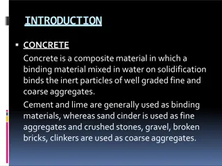
This presentation by Nishant Singh Kushwaha covers the concrete handling process in the field, including batching, mixing, transportation, placing, compacting, curing, and finishing. It emphasizes the stages of producing concrete and highlights the importance of using the correct methods such as volume batching and weigh batching. The presentation also discusses different types of batching machines and provides insights into achieving homogeneous and consistent concrete mixes during the mixing process.

Download Presentation

Please find below an Image/Link to download the presentation.
The content on the website is provided AS IS for your information and personal use only. It may not be sold, licensed, or shared on other websites without obtaining consent from the author. Download presentation by click this link. If you encounter any issues during the download, it is possible that the publisher has removed the file from their server.
E N D
Presentation Transcript
Department of Civil Engineering Concrete Handling in Field By: Nishant Singh Kushwaha Subject Code: 4CE4-08 1
Concrete Handling in field This Powerpoint presentation covers entire unit of Concrete handling in field. Most of the material covers in this ppt and rest if left please refer to M.S Shetty book.
Stages of producing concrete. (1) Batching (2) Mixing (3) Transportation (4) Placing (5) Compacting (6) Curing (7) Finishing 3
(1) Batching (a) Volume batching (b) weight Baching 4
Volume batching Volume batching is not good method Moist sand in loose condition weights less than the same volume of dry sand. Practiced for small work. For quality work ,weigh batching is practiced. 5
VOLUME BATCH Gauge box Various gauge boxes of different volumes are used. Length 33.3 cm 33.3 cm Width 30 cm 30 cm Depth 20 cm 25 cm Volume 20 liters 25 liters Grade Cement- kg Sand -lts Coarse Aggregate lts 70 1:11/2:3 (M 200) 1:2:4 (M 150) 1:3:6 (M100) 50 35 50 70 140 50 105 210 6
Weigh batching Weigh batching is correctmethod Facilitates accuracy, flexibility & simplicity Different batching machine are available : (a) manual machines & (b) Automatic machines Manual machine : Has two buckets Buckets mounted on common spindle about which theyrotate. One is loaded while other is discharged in mixer. Spring loaded dials indicate the weight. 8
Automatic weigh batch For large works Over head hopper and discharges into mixer. Useful in ready mix concrete plant Recorders for weight Calibration is required from time to time. 9
(2) MIXING Mixing of cement,sand aggregates should ensure that: The mass is homogeneous Uniform in color consistent 10
MIXING METHODS : (1) Hand mixing (2) Machine mixing 11
Hand mixing Practiced for small scale work (small house, repairing of house etc) 10 % extra cement is added to compensate inferior concrete produced by this method. Spread fine & coarse aggregate in alternate layer Spread cement over it Mix with shovel till uniform color is achieved
Machine mixing Medium & large scale work use machine mixing Mixing is efficient, economical & produce quality concrete. Type of mixer: (a) Batch mixer : batch by batch with time interval (b) Continuous mixer: continuously mixed & discharged (in dam construction) 13
CONCRETE MIXER (1) Pan type (2) drum Type: (a) tilting (b) Non tilting (c) Reversing 14
PAN MIXER 15
PAN MIXER A forced movement pan mixer has blades that are fixed to an assembly that agitates the concrete throughout the pan as the vertical shaft rotates. 16
DRUM MIXER As per IS: 1791-1985 mixers are designated by number which shows capacity (liters) of batch: a) Tilting : 85 T, 100T, 140 T, 200T b) Non tilting : 200 NT,280 NT, 375 NT, 500 NT, 1000 R c) Reversing : 200 R, 280 R, 375 R,500 R, 1000 R T= Tilting, NT =non tilting, R=Reversing 17
TILTING MIXER Internal blades lift and tumble the ingredients onto itself. Two primary types exist: horizontal (one end has and opening for charging and a different end for discharging) single drum (materials are charged and discharged through a single opening). 19
NON TILTING MIXER Single drum rotating about a horizontal axis. Fixed blades work the concrete towards the discharge end of the mixer, in order to provide a rapid rate of discharge. 21
REVERSING MIXER The entire drum rotates around its axis as materials are loaded through a charge chute at one end of the drum and exit through a discharge chute at the opposite end of the drum. Mixing blades are mounted on the inside surface of the drum and as the drum rotates the blades mix by lifting and dropping the materials during each rotation. Once the materials are sufficiently mixed the rotation of the drum is reversed and the blade arrangement pushes the concrete through to the discharge end of the mixer. 23
Sequence of charging drum First half quantity of coarse aggregate is placed in skip Over it half quantity of sand On that full quantity of cement Over it balance quantity of coarse & fine aggregates is place. This prevents spillage of cement in air while discharging in drum 24
25 % Water is placed in drum and then mix from skip is discharged in the drum This prevents sticking of cement on blades 75 water is immediately poured after placing mix material (cement sand etc) in drum. 25
Mixing time In small machine, mixing time varies between 1-2 minutes In Ready Mix Cement mixer 15-30 seconds RPM of drum : 15-20 Compressive strength of concrete increases with increase in mixing time but after 2 minutes increase in compressive strength is not sign Ki Af Si -2c 01a 2 nt. 25
If concrete is not used after mixing it may set But when concrete is agitated on time to time in drum setting time rule does not follow. 26
Retempering of concrete : Some time concrete from RMC plant is not delivered to site due to traffic congestion Concrete becomes stiff and becomes unworkable Site engineers can reject the concrete if delay is more If it can be of used then small volume of water is added and again agitated in the drum. This is called RETEMPERING OF CONCRETE. 27
MANUFACTURING OF CONCRETE With same material if care is not taken, resulting concrete will be bad concrete What are good rules to make good quality concrete. 29
TRANSPORTATION OF CONCRETE Precaution in concrete transportation: Homogeneity of conc. Mass is maintained Movement of hand trolly or truck on rough road surface makes vibrations This results in deposition of heavy aggregates at bottom of truck Water & cement slurry comes on top. 30
METHODS OF TRANSPORTATION Mortar Pan Wheel barrow Truck Mixer & dumpers Crane, Bucket & rope way Belt conveyors Chutes Skip & hoist Transit Mixer Pump & pipeline Helicopter 1. 2. 3. 4. 5. 6. 7. 8. 9. 10. 31
MORTAR PAN Common method in India More labour required Segregation of concrete is less Greater surface area of concrete is exposed to sun, concrete dries. 32
WHEEL BARROW When transportation of concrete is at ground level. Movement of wheel on rough road surface, segregates concrete. Some wheel barrows have pneumatic wheel to reduce vibration 33
CRANE Used for transporting concrete above ground level. For high rise buildings. Cranes are fast Can move horizontally & vertically Concrete in skip discharge from bottom In bucket concrete is discharged by tilting. 34
BUCKET & ROPEWAY Use for construction in: Valley Bridge pier in river Dam Advantage: Concrete is not exposed to sun or air & no loss of water. 35
Truck Mixer & dumpers Used for large concrete works. Can travel any part of site. Dumpers - 2-3 M3Capacity Trucks 4 M3Capacity Bottom surface of truck is kept wet Top of truck is covered to prevent evaporation 36
BELT CONVEYORS Limited use in construction Advantages: Can transport large volume Very quick Can go where access is limited Disadvantages : On steep slope concretesegregates. Exposed to sun for long time. 37
CHUTE For transporting from ground level to lower level. (basement etc). Used where labour can not reach due to less space in trench etc. Made of metal Slope should not be < 1 vertical : 2.5 horizontal. 38
SKIP & HOIST Labour can go upto 3rd or 4th floors. So skip is used for transport vertically up (in multistory building). Skip travels on vertical rail. Skip can discharge manually or automatically. 39
TRANSIT MIXER Used for long distance travel in RMC plant. Concrete is continuously agitated in truck drum (2 6 rpm). Also transported mix in dry condition and water is added on reaching the destination. Wet Mix in truck must reach site in 1- 1.5 hours. Pumps are also fitted on truck mixer to discharge concrete. 41
PUMPS & PIPELINE Most popular method Reliable & good quality pumps are used. Mostly operated by diesel. Concrete is placed in collecting hopper. Rotating blades in hopper pushes concrete towards pipe. Vacume in hose pipe (600 mm Hg) Rotating rollers in pump chambers squeeze the concrete in pipe and flow of concrete is started. Concrete is discharged from other end of hose pipe. Concrete can be pumped upto 400 m height and 2000 m distance. 42
PIPELINE Pipeline should : Have correct diameter as per pump pressure. (generally 125 mm) Have sufficient thickness Good couplings Poor pipeline can cause blockage. 44
PIPELINE Thumb rule : For 30 M3 /hr concrete and 200 m length, dia should be 100 mm. Length > 500 m then dia = 150 mm. Dia = 3 to 4 times the size of aggregate Leaky pipe & coupling result in escape of water /air & finally block the concrete. Vertical pipe should good otherwise difficult to change at height. Pump is kept at distance from building about 15 % of vertical length. KAS-2012 44
PUMPABLE CONCRETE Concrete which can be pushed through a pipeline is called pumpable concrete. Friction between pipe wall and concrete is less. Concrete flows in the form of plug which is separated from pipe wall by a thin layer of lubricating cement paste. Flow resistant must be < pump pressure. If the concrete is more wet then water comes out of mix which makes more resistance to flow. Stiff and also very wet concrete is not pumpable. 46
Design of pumpable concrete Concrete Mix is so designed that all material remain together. Mix must make redial movement of grout to maintain lubricating paste. Mix should be deformed at bends Cement & fine particles (0.25 mm size) are important for good flow. 350 to 400 Kg/ M3 of fine particles are necessaryfor flow. Slump of pumpable concrete is above 75 mm. 47
PROBLEMS IN PUMPING Blockage in pipe Pipe should be cleaned after each day operation Blockage can be cleaned by forward- backward pumping. Tapping pipe with hammer Clean pipe with rod or sponge ball pushed by compressed air. 48
PLACING CONCRETE Must be placed in systematic manner. Can be placed with following methods: Within earth mould : Foundation In timber plank formwork : Road, airport slab. Steel shuttering : Dam Under water 49
Concrete in Foundation In foundation, ground is made wet. Plastic sheet are laid between ground & slab Concrete is dumped not poured. No heap and dragging Placed in layers of 35 40 cm in mass concrete Avoid cold joints between 2 layers Surface of previous layer is cleaned with wire brush Sometime, cement slurry is placed on old surface Top of previous layer kept rough for good bond. 50


 Batching")


 MIXING")