Caterpillar Cat TH63 Telehandler (Prefix 5WM) Service Repair Manual Instant Download (5WM00001-06020)
Please open the website below to get the complete manualnn// n
Download Presentation

Please find below an Image/Link to download the presentation.
The content on the website is provided AS IS for your information and personal use only. It may not be sold, licensed, or shared on other websites without obtaining consent from the author. Download presentation by click this link. If you encounter any issues during the download, it is possible that the publisher has removed the file from their server.
E N D
Presentation Transcript
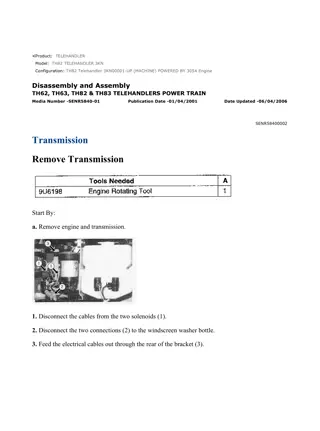
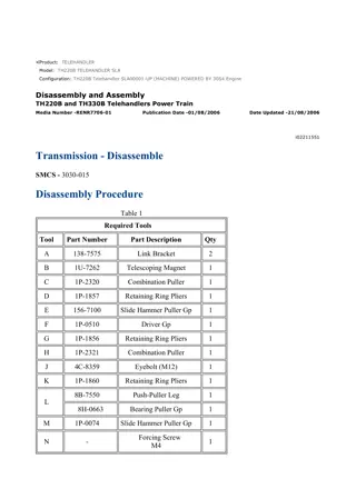
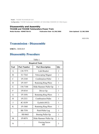
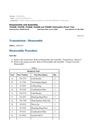
w 1/51(W) Product: TELEHANDLER Model: TH63 TELEHANDLER 5WM Configuration: TH63 Telehandler 5WM00001-06020 (MACHINE) POWERED BY 3054 Engine Disassembly and Assembly TH62, TH63, TH82, TH83 and TH103 Telehandlers Power Train Media Number -RENR3436-06 Publication Date -01/07/2004 Date Updated -23/02/2017 i02163125 Transmission - Disassemble SMCS - 3030-015 S/N - 3JN791-UP S/N - 3RN2387-UP S/N - 4TM2303-UP S/N - 5WM3797-UP Disassembly Procedure Table 1 Required Tools Tool Part Number Part Description Qty A 2P-8250 Strap Wrench As 1 B 126-0413 Wrench 1 C 1P-0510 Driver Gp 1 D 156-7100 Slide Hammer Puller Gp 1 E 1P-1853 Retaining Ring Pliers 1 F 1P-2321 Combination Puller 1 G FT-2508 Spring Compressor 1 H 1P-1860 Retaining Ring Pliers 1 I 1P-1859 Retaining Ring Pliers 1 J 5F-7366 Forcing Screw 1 https://127.0.0.1/sisweb/sisweb/techdoc/techdoc_print_page.jsp?returnurl=/sisweb/sisw... 2023/2/16
w 2/51(W) 8B-7550 Push-Puller Leg 2 1B-4207 Full Nut 2 3H-0465 Push-Puller Plate 4 8H-0663 Bearing Puller 1 5F-7353 Washer 1 5B-0637 High Idle Nut 1 1U-9895 Crossblock 1 K 1P-7600 Puller 1 L 136-1452 Internal Tip Pliers 1 M 1P-0074 Slide Hammer Puller Gp 1 Illustration 1 g00718305 1. Remove bolts (2) and washers (3) in order to remove bracket (1). Remove bolts (5) and washers (6) in order to remove bracket (4). Remove fitting (7) . https://127.0.0.1/sisweb/sisweb/techdoc/techdoc_print_page.jsp?returnurl=/sisweb/sisw... 2023/2/16
w 3/51(W) Illustration 2 g00718310 2. Remove test fitting (8) and test fitting (9) . Illustration 3 g00718315 3. Remove bolts (11) and allen head screw (12) from gear pump (10) . Illustration 4 g00718323 4. Remove gear pump (10) and gasket (13) . https://127.0.0.1/sisweb/sisweb/techdoc/techdoc_print_page.jsp?returnurl=/sisweb/sisw... 2023/2/16
https://www.ebooklibonline.com Hello dear friend! Thank you very much for reading. Enter the link into your browser. The full manual is available for immediate download. https://www.ebooklibonline.com
w 4/51(W) Illustration 5 g00718328 5. Use Tooling (A) in order to remove filter (14) . Illustration 6 g00718639 6. Use Tooling (B) in order to remove valve sleeve (15). Illustration 7 g00718638 https://127.0.0.1/sisweb/sisweb/techdoc/techdoc_print_page.jsp?returnurl=/sisweb/sisw... 2023/2/16
w 5/51(W) 7. Use a hammer and a punch in order to push pin (16) out of valve sleeve (15). Remove piston (18) and spring (17) . Illustration 8 g00718674 8. Remove bolts (19) and washers (20) from housing (21) . Illustration 9 g00718683 9. Remove allen head screw (22) from housing (21) . https://127.0.0.1/sisweb/sisweb/techdoc/techdoc_print_page.jsp?returnurl=/sisweb/sisw... 2023/2/16
w 6/51(W) Illustration 10 g00718962 10. Carefully remove housing (21) and gasket (23) . Illustration 11 g00718964 11. Remove bearing (24) from housing (21) . Illustration 12 g01096866 12. Remove oil distributor (25) from housing (21) . https://127.0.0.1/sisweb/sisweb/techdoc/techdoc_print_page.jsp?returnurl=/sisweb/sisw... 2023/2/16
w 7/51(W) Illustration 13 g00718966 13. Use Tooling (C) in order to remove seal (27) from housing (21) . Illustration 14 g00718967 14. Remove plug (28) from housing (21) . https://127.0.0.1/sisweb/sisweb/techdoc/techdoc_print_page.jsp?returnurl=/sisweb/sisw... 2023/2/16
w 8/51(W) Illustration 15 g00718969 15. Remove set screw (29) . Illustration 16 g00718970 16. Use Tooling (D) in order to remove sleeve (30) from housing (21) . Illustration 17 g00718979 17. Remove plug (31) from housing (21) . https://127.0.0.1/sisweb/sisweb/techdoc/techdoc_print_page.jsp?returnurl=/sisweb/sisw... 2023/2/16
w 9/51(W) Illustration 18 g00718983 18. Remove set screw (32) . Illustration 19 g00718986 19. Use Tooling (D) in order to remove sleeve (33) from housing (21) . Illustration 20 g00719061 20. Remove hub gear (34) for the torque converter impeller. https://127.0.0.1/sisweb/sisweb/techdoc/techdoc_print_page.jsp?returnurl=/sisweb/sisw... 2023/2/16
w 10/51(W) Illustration 21 g00719067 21. Remove thrust washer (35), roller bearing (36), and drive gear (37) from idler shaft (38) . Illustration 22 g00719073 22. Remove idler shaft (38) and thrust washer (39) from spacer plate (40) . https://127.0.0.1/sisweb/sisweb/techdoc/techdoc_print_page.jsp?returnurl=/sisweb/sisw... 2023/2/16
w 11/51(W) Illustration 23 g00719079 23. Remove bolts (42) and remove cover (43) which protects the solenoid valves. Illustration 24 g00719082 24. Remove retaining nut (44) for the solenoid cartridge. Remove O-ring seal (45) . Illustration 25 g00719087 25. Remove solenoid coil (46) and O-ring seal (47) . 26. Repeat steps 24 through 25 in order to remove the remaining four solenoid coils. https://127.0.0.1/sisweb/sisweb/techdoc/techdoc_print_page.jsp?returnurl=/sisweb/sisw... 2023/2/16
w 12/51(W) Illustration 26 g00719091 27. Remove solenoid valve cartridge (48). Remove four O-ring seals (49) from solenoid valve (48) . 28. Repeat step 27 in order to remove the remaining four solenoid valves. Illustration 27 g00719306 29. Place transmission case (50) on a suitable work bench. Remove bolts (51) and washers (52) from spacer plate (40). https://127.0.0.1/sisweb/sisweb/techdoc/techdoc_print_page.jsp?returnurl=/sisweb/sisw... 2023/2/16
w 13/51(W) Illustration 28 g00719307 30. Carefully pry spacer plate (40) away from transmission case (50). At the same time strike shaft (53) and shaft (54) with a rubber mallet. This will remove two internal bearings from spacer plate (40). Carefully remove spacer plate (40) from transmission case (50). Illustration 29 g00719308 31. Support spacer plate (40) with suitable cribbing on a work bench. Remove bolt (55), washer (56), and thrust washer (57) . Illustration 30 g00719309 32. Remove gear (58), roller bearing (59), and thrust washer (60) from shaft (61) . https://127.0.0.1/sisweb/sisweb/techdoc/techdoc_print_page.jsp?returnurl=/sisweb/sisw... 2023/2/16
w 14/51(W) Illustration 31 g00719311 33. Remove oil ring (62) and the expander ring. Remove snap ring (63) and thrust washer (64). Push stator support (65) into spacer plate (40). Turn spacer plate (40) onto the opposite side. Illustration 32 g00719315 34. Remove snap ring (66) from stator support (65) . Illustration 33 g00719317 https://127.0.0.1/sisweb/sisweb/techdoc/techdoc_print_page.jsp?returnurl=/sisweb/sisw... 2023/2/16
w 15/51(W) 35. Vertically position spacer plate (40) and support with suitable cribbing. Remove stator support (65) from spacer plate (40) . Illustration 34 g00719375 36. Remove needle bearing (67) from stator support (65) . Illustration 35 g00719381 37. Remove bushing (68) from stator support (65) . https://127.0.0.1/sisweb/sisweb/techdoc/techdoc_print_page.jsp?returnurl=/sisweb/sisw... 2023/2/16
w 16/51(W) Illustration 36 g00719399 Personal injury can result from being struck by parts propelled by a released spring force. Make sure to wear all necessary protective equipment. Follow the recommended procedure and use all recommended tooling to release the spring force. 38. Compress spring (70) for the safety valve and remove retaining cap (69). Remove poppet valve (71) from the opposite side of spacer plate (40) . Illustration 37 g00719417 39. Turn spacer plate (40) onto the opposite side. Use Tooling (E) in order to remove snap ring (72). Use Tooling (C) in order to remove valve seat (73) . https://127.0.0.1/sisweb/sisweb/techdoc/techdoc_print_page.jsp?returnurl=/sisweb/sisw... 2023/2/16
w 17/51(W) Illustration 38 g00719470 40. Remove gasket (74) from transmission case (50) . 41. Use steps 42 through 67 in order to disassemble the first speed and second speed clutches. Illustration 39 g00719473 42. Remove the first speed and second speed clutches (75) from transmission case (50) . Illustration 40 g00719479 https://127.0.0.1/sisweb/sisweb/techdoc/techdoc_print_page.jsp?returnurl=/sisweb/sisw... 2023/2/16
w 18/51(W) 43. Support the first speed and the second speed clutch on suitable cribbing. Remove two oil rings (76) from shaft (77) . Illustration 41 g00719483 44. Use Tooling (F) in order to remove roller bearing (78) from shaft (77) . Illustration 42 g00719489 45. Remove two washers (79) and bearing (80) from shaft (77) . https://127.0.0.1/sisweb/sisweb/techdoc/techdoc_print_page.jsp?returnurl=/sisweb/sisw... 2023/2/16
w 19/51(W) Illustration 43 g00719490 46. Remove gear (81) from shaft (77) . Illustration 44 g00719491 47. Support gear (81) on suitable cribbing. Use Tooling (C) in order to remove two needle bearings (82) . Illustration 45 g00719494 https://127.0.0.1/sisweb/sisweb/techdoc/techdoc_print_page.jsp?returnurl=/sisweb/sisw... 2023/2/16
w 20/51(W) 48. Remove washers (83) and bearing (84) from shaft (77) . Illustration 46 g00719496 49. Use a screwdriver to remove snap ring (85) . Illustration 47 g00719498 50. Remove end plate (86) from shaft (77) . https://127.0.0.1/sisweb/sisweb/techdoc/techdoc_print_page.jsp?returnurl=/sisweb/sisw... 2023/2/16
w 21/51(W) Illustration 48 g00719503 51. Remove clutch plates (87) and friction discs (88) from shaft (77) . Illustration 49 g00723283 Personal injury can result from being struck by parts propelled by a released spring force. Make sure to wear all necessary protective equipment. Follow the recommended procedure and use all recommended tooling to release the spring force. 52. Use Tooling (G) with a suitable press to compress springs (89). Use Tooling (I) and release snap ring (90) from shaft (77). Carefully release the spring tension and remove Tooling (G) . https://127.0.0.1/sisweb/sisweb/techdoc/techdoc_print_page.jsp?returnurl=/sisweb/sisw... 2023/2/16
w 22/51(W) Illustration 50 g00720055 53. Place shaft (77) on suitable cribbing and remove snap ring (90) . Illustration 51 g00720057 54. Remove ring retainer (91) from shaft (77) . Illustration 52 g00720059 55. Remove springs (89) from shaft (77) . https://127.0.0.1/sisweb/sisweb/techdoc/techdoc_print_page.jsp?returnurl=/sisweb/sisw... 2023/2/16
Suggest: For more complete manuals. Please go to the home page. https://www.ebooklibonline.com If the above button click is invalid. Please download this document first, and then click the above link to download the complete manual. Thank you so much for reading
w 23/51(W) Illustration 53 g00720242 56. Remove wear plate (92) from shaft (77) . Illustration 54 g00721508 57. Remove piston (93) from shaft (77). Remove outer sealing ring (94) and inner sealing ring (95) from piston (93) . Illustration 55 g00719967 https://127.0.0.1/sisweb/sisweb/techdoc/techdoc_print_page.jsp?returnurl=/sisweb/sisw... 2023/2/16
w 24/51(W) 58. Turn shaft (77) onto the opposite side and support with suitable cribbing. Use Tooling (F) in order to remove gear (97) and bearing (96) from shaft (77) . Illustration 56 g00719975 59. Use Tooling (H) in order to remove two snap rings (98) from shaft (77) . Illustration 57 g00719988 60. Remove washers (99) and bearing (100) from shaft (77) . https://127.0.0.1/sisweb/sisweb/techdoc/techdoc_print_page.jsp?returnurl=/sisweb/sisw... 2023/2/16
https://www.ebooklibonline.com Hello dear friend! Thank you very much for reading. Enter the link into your browser. The full manual is available for immediate download. https://www.ebooklibonline.com

