Caterpillar Cat D5M TRACK-TYPE TRACTOR (Prefix 7LR) Service Repair Manual Instant Download (7LR00001 and up)
Please open the website below to get the complete manualnn// n
Download Presentation

Please find below an Image/Link to download the presentation.
The content on the website is provided AS IS for your information and personal use only. It may not be sold, licensed, or shared on other websites without obtaining consent from the author. Download presentation by click this link. If you encounter any issues during the download, it is possible that the publisher has removed the file from their server.
E N D
Presentation Transcript
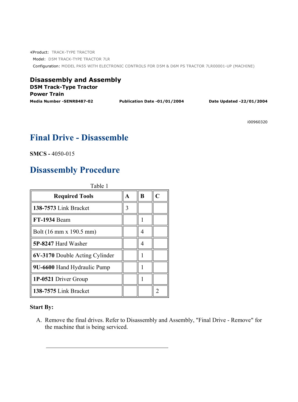
MODEL PA55 WITH ELECTRONIC CONTROLS FOR D5M & D6M PS TRACTO... 1/6 Product: TRACK-TYPE TRACTOR Model: D5M TRACK-TYPE TRACTOR 7LR Configuration: MODEL PA55 WITH ELECTRONIC CONTROLS FOR D5M & D6M PS TRACTOR 7LR00001-UP (MACHINE) Disassembly and Assembly D5M Track-Type Tractor Power Train Media Number -SENR8487-02 Publication Date -01/01/2004 Date Updated -22/01/2004 i00960320 Final Drive - Disassemble SMCS - 4050-015 Disassembly Procedure Table 1 Required Tools A B C 138-7573 Link Bracket 3 FT-1934 Beam 1 Bolt (16 mm x 190.5 mm) 4 5P-8247 Hard Washer 4 6V-3170 Double Acting Cylinder 1 9U-6600 Hand Hydraulic Pump 1 1P-0521 Driver Group 1 138-7575 Link Bracket 2 Start By: A. Remove the final drives. Refer to Disassembly and Assembly, "Final Drive - Remove" for the machine that is being serviced. https://127.0.0.1/sisweb/sisweb/techdoc/techdoc_print_page.jsp?returnurl=/sis... 2022/3/27
MODEL PA55 WITH ELECTRONIC CONTROLS FOR D5M & D6M PS TRACTO... 2/6 Illustration 1 g00558491 1. Fasten a hoist and Tooling (A) to carrier (1). Remove bolts (2) and remove the carrier. The weight of the carrier is 41 kg (90.0 lb). Illustration 2 g00558493 2. Remove bolts (3) and plates (4) from carrier (1) . Illustration 3 g00558494 https://127.0.0.1/sisweb/sisweb/techdoc/techdoc_print_page.jsp?returnurl=/sis... 2022/3/27
MODEL PA55 WITH ELECTRONIC CONTROLS FOR D5M & D6M PS TRACTO... 3/6 Illustration 4 g00558495 3. Use a press and push shaft (5) out of carrier (1) . 4. Remove gear (8). Remove bearing cones (6) and (9) from the carrier. 5. If necessary, remove bearing cups (7) from gear (8) . Illustration 5 g00558496 6. Remove bolts (10) and retainer (11) from the spindle. https://127.0.0.1/sisweb/sisweb/techdoc/techdoc_print_page.jsp?returnurl=/sis... 2022/3/27
https://www.ebooklibonline.com Hello dear friend! Thank you very much for reading. Enter the link into your browser. The full manual is available for immediate download. https://www.ebooklibonline.com
MODEL PA55 WITH ELECTRONIC CONTROLS FOR D5M & D6M PS TRACTO... 4/6 Illustration 6 g00558498 7. Remove hub (13) and gear (14) from the final drive as an assembly. Illustration 7 g00558499 8. Remove ring (15) and hub (13) from gear (14) . Illustration 8 g00558501 https://127.0.0.1/sisweb/sisweb/techdoc/techdoc_print_page.jsp?returnurl=/sis... 2022/3/27
MODEL PA55 WITH ELECTRONIC CONTROLS FOR D5M & D6M PS TRACTO... 5/6 Note: Do not lift the hub so that the hub makes contact with the fittings that are on the hydraulic cylinder. Damage to the fittings could occur. 9. Heat bearing cone (16) to a maximum temperature of 120 C (248.0 F). Use Tooling (B) in order to remove bearing cone (16) from the spindle. 10. Remove Tooling (B) and bearing cone (16) . Illustration 9 g00558502 11. Fasten a hoist and Tooling (C) to hub (17). Remove the hub from the spindle. Illustration 10 g00558506 12. Remove Duo-cone seal kit (18) from the hub. 13. If necessary, remove bearing cups (19) and (20) from the hub. https://127.0.0.1/sisweb/sisweb/techdoc/techdoc_print_page.jsp?returnurl=/sis... 2022/3/27
MODEL PA55 WITH ELECTRONIC CONTROLS FOR D5M & D6M PS TRACTO... 6/6 Illustration 11 g00558507 14. Remove Duo-cone seal kit (23) from spindle (21) . 15. Remove seal (22) from the spindle. 16. If necessary, remove bearing cone (24) from spindle (21) . https://127.0.0.1/sisweb/sisweb/techdoc/techdoc_print_page.jsp?returnurl=/sis... 2022/3/27
MODEL PA55 WITH ELECTRONIC CONTROLS FOR D5M & D6M PS TRACTO... 1/6 Product: TRACK-TYPE TRACTOR Model: D5M TRACK-TYPE TRACTOR 7LR Configuration: MODEL PA55 WITH ELECTRONIC CONTROLS FOR D5M & D6M PS TRACTOR 7LR00001-UP (MACHINE) Disassembly and Assembly D5M Track-Type Tractor Power Train Media Number -SENR8487-02 Publication Date -01/01/2004 Date Updated -22/01/2004 i00960318 Final Drive - Assemble SMCS - 4050-016 Assembly Procedure Table 1 Required Tools A B C D E 1P-0520 Driver Group 1 8M-9395 Seal Installer 1 138-7575 Link Bracket 2 8T-3225 Spacer 1 138-7573 Link Bracket 3 Illustration 1 g00558510 https://127.0.0.1/sisweb/sisweb/techdoc/techdoc_print_page.jsp?returnurl=/sis... 2022/3/27
MODEL PA55 WITH ELECTRONIC CONTROLS FOR D5M & D6M PS TRACTO... 2/6 1. Use Tooling (A) in order to install seal (1) in the hub. Install the seal with the lip downward, as shown. 2. If bearing (3) was removed, heat the bearing cone to a maximum temperature of 120 C (248 F). Install the bearing cone on the spindle. Note: Before installing any of the Duo-Cone seal kits, see Disassembly and Assembly, "Duo-Cone Conventional Seals - Install". 3. Use Tooling (B) in order to install Duo-Cone seal kit (2) on the spindle. Illustration 2 g00558523 4. If bearing cups (5) and (6) were removed from the hub, lower the temperature of the bearing cups and install the cups in the hub. 5. Use Tooling (B) in order to install Duo-Cone seal kit (4) in the hub. Illustration 3 g00558544 6. Fasten a hoist and Tooling (C) to hub (7). Lower the hub into position on spindle (8) . https://127.0.0.1/sisweb/sisweb/techdoc/techdoc_print_page.jsp?returnurl=/sis... 2022/3/27
MODEL PA55 WITH ELECTRONIC CONTROLS FOR D5M & D6M PS TRACTO... 3/6 Illustration 4 g00558546 Illustration 5 g00558548 7. Heat bearing cone (9) to a maximum temperature of 120 C (248 F) and install the bearing cone on the spindle. 8. While bearing cone (9) is still hot, put Tooling (D) into position. Install retainer (10) and bolts (11). Tighten the bolts to a torque of 135 15 N m (100.0 11 lb ft). 9. After the bearing has cooled, remove the retainer and Tooling (D) . https://127.0.0.1/sisweb/sisweb/techdoc/techdoc_print_page.jsp?returnurl=/sis... 2022/3/27
MODEL PA55 WITH ELECTRONIC CONTROLS FOR D5M & D6M PS TRACTO... 4/6 Illustration 6 g00558550 10. Put hub (14) into position in gear (12) and install ring (13) . Illustration 7 g00558554 11. Put hub (14) and gear (12) into position on the spindle as an assembly. 12. Install retainer (10) and bolt (11). Tighten the bolts to a torque of 135 15 N m (100 11 lb ft). 13. Use a feeler gauge in order to verify that there is metal to metal contact between retainer (10) and the spindle. Illustration 8 g00558557 https://127.0.0.1/sisweb/sisweb/techdoc/techdoc_print_page.jsp?returnurl=/sis... 2022/3/27
MODEL PA55 WITH ELECTRONIC CONTROLS FOR D5M & D6M PS TRACTO... 5/6 Illustration 9 g00558559 14. If bearing cups (17) were removed from gear (18), lower the temperature of the bearing cups and install the cups in gear (18) . 15. Put bearing cones (16) and (19) into position in gear (18) . 16. Put the bearing cones and gear (18) into position in carrier (20). Lower the temperature of shaft (21). Use a press and install shaft (21) in the carrier. Install the shaft until the end of the shaft is even with the outer surface of the carrier. Illustration 10 g00558560 17. Install plates (23) and bolts (22). Verify that there is metal to metal contact between plates (23) and the shafts. https://127.0.0.1/sisweb/sisweb/techdoc/techdoc_print_page.jsp?returnurl=/sis... 2022/3/27
MODEL PA55 WITH ELECTRONIC CONTROLS FOR D5M & D6M PS TRACTO... 6/6 Illustration 11 g00558563 18. Fasten a hoist and Tooling (E) to carrier (20). Put the carrier into position in hub (7) and install bolts (24) . End By: Install the final drives. Refer to Disassembly and Assembly, "Final Drive - Install" for the machine that is being serviced. https://127.0.0.1/sisweb/sisweb/techdoc/techdoc_print_page.jsp?returnurl=/sis... 2022/3/27
MODEL PA55 WITH ELECTRONIC CONTROLS FOR D5M & D6M PS TRACTO... 1/3 Product: TRACK-TYPE TRACTOR Model: D5M TRACK-TYPE TRACTOR 7LR Configuration: MODEL PA55 WITH ELECTRONIC CONTROLS FOR D5M & D6M PS TRACTOR 7LR00001-UP (MACHINE) Disassembly and Assembly D5M Track-Type Tractor Power Train Media Number -SENR8487-02 Publication Date -01/01/2004 Date Updated -22/01/2004 i00960322 Final Drive - Install SMCS - 4050-012 Installation Procedure Table 1 Required Tools A B 8T-3207 Lifting Bracket 1 5P-8622 Shackle 1 Bolt (20 mm x 133 mm Long) 2 9S-9076 Spacer 2 1P-3533 Carrier Bar 1 1. Install the O-ring seal on the steering clutch and the brake housing. Put clean oil on the O- ring seal. https://127.0.0.1/sisweb/sisweb/techdoc/techdoc_print_page.jsp?returnurl=/sis... 2022/3/27
MODEL PA55 WITH ELECTRONIC CONTROLS FOR D5M & D6M PS TRACTO... 2/3 Illustration 1 g00558490 Illustration 2 g00558488 2. Fasten a hoist and Tooling (A) to final drive (3). Use Tooling (B) in order to balance the final drive. Put the final drive (3) in position on the steering clutch and the brake housing. Install bolts (5) and (6) . Illustration 3 g00558484 3. Remove Tooling (A) from the final drive. https://127.0.0.1/sisweb/sisweb/techdoc/techdoc_print_page.jsp?returnurl=/sis... 2022/3/27
MODEL PA55 WITH ELECTRONIC CONTROLS FOR D5M & D6M PS TRACTO... 3/3 Illustration 4 g00558352 4. Remove the three bolts and cover (1) . End By: a. Install the axles. Refer to Disassembly and Assembly, "Axle - Remove and Install" for the machine that is being serviced. b. Connect the tracks. Refer to Disassembly and Assembly, "Track - Connect" for the machine that is being serviced. https://127.0.0.1/sisweb/sisweb/techdoc/techdoc_print_page.jsp?returnurl=/sis... 2022/3/27
MODEL PA55 WITH ELECTRONIC CONTROLS FOR D5M & D6M PS TRACTO... 1/8 Product: TRACK-TYPE TRACTOR Model: D5M TRACK-TYPE TRACTOR 7LR Configuration: MODEL PA55 WITH ELECTRONIC CONTROLS FOR D5M & D6M PS TRACTOR 7LR00001-UP (MACHINE) Disassembly and Assembly D5M Track-Type Tractor Power Train Media Number -SENR8487-02 Publication Date -01/01/2004 Date Updated -22/01/2004 i00960735 Steering Clutch and Brake - Disassemble SMCS - 4100-015 Disassembly Procedure Table 1 Required Tools A 138-7575 Link Bracket 3 Start By: A. Separate the final drive, steering clutches and brakes. Refer to Disassembly and Assembly, "Final Drive, Steering Clutch and Brake - Separate" for the machine that is being serviced. Illustration 1 g00558564 1. Remove bolts (1) and (2) . https://127.0.0.1/sisweb/sisweb/techdoc/techdoc_print_page.jsp?returnurl=/sis... 2022/3/27
MODEL PA55 WITH ELECTRONIC CONTROLS FOR D5M & D6M PS TRACTO... 2/8 Illustration 2 g00558708 2. Remove sleeve bearings (3) from plate (2) . Illustration 3 g00558709 3. Remove input hub (4) . https://127.0.0.1/sisweb/sisweb/techdoc/techdoc_print_page.jsp?returnurl=/sis... 2022/3/27
MODEL PA55 WITH ELECTRONIC CONTROLS FOR D5M & D6M PS TRACTO... 3/8 Illustration 4 g00558711 4. Remove clutch plates (5) and friction discs (6) from hub assembly (7) . Illustration 5 g00558712 Illustration 6 g00558716 5. Remove piston (8) from hub assembly (7) . 6. Remove sleeve bearing (9) . 7. Remove seals (10) and (11) from piston (8) . https://127.0.0.1/sisweb/sisweb/techdoc/techdoc_print_page.jsp?returnurl=/sis... 2022/3/27
MODEL PA55 WITH ELECTRONIC CONTROLS FOR D5M & D6M PS TRACTO... 4/8 Illustration 7 g00558717 8. Turn over the brake assembly. 9. Remove ring (12) from hub assembly (7) . Illustration 8 g00558719 10. Fasten a hoist and Tooling (A) to housing (13). Remove the brake assembly from hub assembly (7). The weight of the brake assembly is 86 kg (190 lb). https://127.0.0.1/sisweb/sisweb/techdoc/techdoc_print_page.jsp?returnurl=/sis... 2022/3/27
MODEL PA55 WITH ELECTRONIC CONTROLS FOR D5M & D6M PS TRACTO... 5/8 Illustration 9 g00558720 11. Remove bearing (14) from housing (13) . Illustration 10 g00558721 12. Remove three rings (15) from hub assembly (7) . 13. Remove bearing (16) from the hub assembly. Personal injury can result from parts under high spring pressure. Spring force can cause parts to come off suddenly. Contact your Caterpillar dealer for disassembly instructions before removing any parts. Illustration 11 g00558722 https://127.0.0.1/sisweb/sisweb/techdoc/techdoc_print_page.jsp?returnurl=/sis... 2022/3/27
MODEL PA55 WITH ELECTRONIC CONTROLS FOR D5M & D6M PS TRACTO... 6/8 Note: Make sure that you remove bolts (17) before you remove bolts (19). Bolts (19) hold a spring that is under compression. 14. Remove bolts (17) and plate (18) from housing (13) . Illustration 12 g00558724 15. Remove brake plates (20) and friction discs (21) from the housing. Personal injury can result from parts under high spring pressure. Spring force can cause parts to come off suddenly. Contact your Caterpillar dealer for disassembly instructions before removing any parts. Illustration 13 g00558725 Note: Make sure that you slowly loosen and evenly loosen bolts (19) . https://127.0.0.1/sisweb/sisweb/techdoc/techdoc_print_page.jsp?returnurl=/sis... 2022/3/27
MODEL PA55 WITH ELECTRONIC CONTROLS FOR D5M & D6M PS TRACTO... 7/8 16. Remove bolts (19) and manifold assembly (22) from housing (13) . Illustration 14 g00558726 17. Remove seals (23) and (24) from manifold assembly (22) . Illustration 15 g00558727 18. Remove piston (25) from housing (13) . https://127.0.0.1/sisweb/sisweb/techdoc/techdoc_print_page.jsp?returnurl=/sis... 2022/3/27
MODEL PA55 WITH ELECTRONIC CONTROLS FOR D5M & D6M PS TRACTO... 8/8 Illustration 16 g00558728 19. Remove springs (26) from housing (13) . Note: Note the direction of spring (26) before removing. 20. Remove O-ring seals (27) and (28) . https://127.0.0.1/sisweb/sisweb/techdoc/techdoc_print_page.jsp?returnurl=/sis... 2022/3/27
MODEL PA55 WITH ELECTRONIC CONTROLS FOR D5M & D6M PS TRACTO... 1/9 Product: TRACK-TYPE TRACTOR Model: D5M TRACK-TYPE TRACTOR 7LR Configuration: MODEL PA55 WITH ELECTRONIC CONTROLS FOR D5M & D6M PS TRACTOR 7LR00001-UP (MACHINE) Disassembly and Assembly D5M Track-Type Tractor Power Train Media Number -SENR8487-02 Publication Date -01/01/2004 Date Updated -22/01/2004 i00960734 Steering Clutch and Brake - Assemble SMCS - 4100-016 Assembly Procedure Table 1 Required Tools A B 138-7575 Link Bracket 3 1P-0510 Driver Group 1 1. Clean all parts. Inspect all parts for wear or damage. Replace all parts that are damaged or worn. Illustration 1 g00558728 2. Install springs (26) in housing (13) . https://127.0.0.1/sisweb/sisweb/techdoc/techdoc_print_page.jsp?returnurl=/sis... 2022/3/27
Suggest: For more complete manuals. Please go to the home page. https://www.ebooklibonline.com If the above button click is invalid. Please download this document first, and then click the above link to download the complete manual. Thank you so much for reading
MODEL PA55 WITH ELECTRONIC CONTROLS FOR D5M & D6M PS TRACTO... 2/9 3. Install O-ring seals (27) and (28) . Illustration 2 g00558727 4. Put piston (25) into position in housing (13) . Illustration 3 g00558726 5. Install seals (23) and (24) on manifold assembly (22). Install the seals on the manifold assembly, as shown. Put clean oil on the lip of the seals. https://127.0.0.1/sisweb/sisweb/techdoc/techdoc_print_page.jsp?returnurl=/sis... 2022/3/27
MODEL PA55 WITH ELECTRONIC CONTROLS FOR D5M & D6M PS TRACTO... 3/9 Illustration 4 g00558725 6. Align the oil holes in manifold assembly (22) with the holes in housing (13). Install the manifold assembly and bolts (19) . Illustration 5 g00675073 Prepare New Seal Rings for Installation by Using This Method. Illustration 6 g00675075 https://127.0.0.1/sisweb/sisweb/techdoc/techdoc_print_page.jsp?returnurl=/sis... 2022/3/27
https://www.ebooklibonline.com Hello dear friend! Thank you very much for reading. Enter the link into your browser. The full manual is available for immediate download. https://www.ebooklibonline.com

