Caterpillar Cat 983 TRACK LOADER (Prefix 38K) Service Repair Manual Instant Download (38K00765 and up)
Please open the website below to get the complete manualnn//
Download Presentation

Please find below an Image/Link to download the presentation.
The content on the website is provided AS IS for your information and personal use only. It may not be sold, licensed, or shared on other websites without obtaining consent from the author. Download presentation by click this link. If you encounter any issues during the download, it is possible that the publisher has removed the file from their server.
E N D
Presentation Transcript
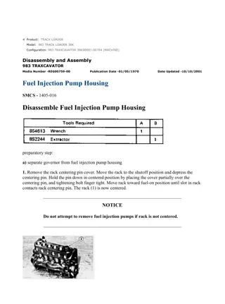
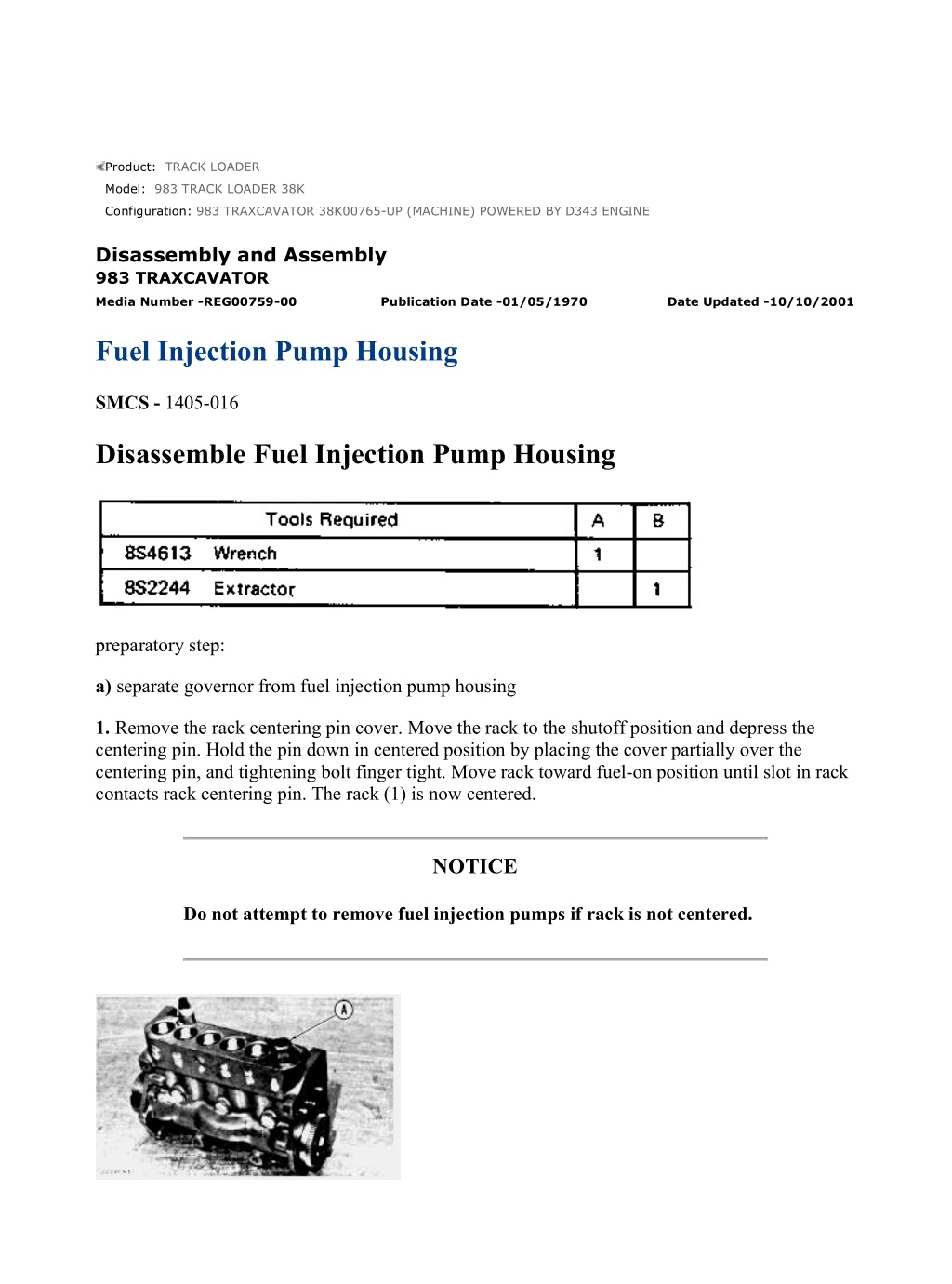
983 TRAXCAVATOR 38K00765-UP (MACHINE) POWERED BY D343 ENGINE(... 1/5 Product: TRACK LOADER Model: 983 TRACK LOADER 38K Configuration: 983 TRAXCAVATOR 38K00765-UP (MACHINE) POWERED BY D343 ENGINE Disassembly and Assembly 983 TRAXCAVATOR Media Number -REG00759-00 Publication Date -01/05/1970 Date Updated -10/10/2001 Fuel Injection Pump Housing SMCS - 1405-016 Disassemble Fuel Injection Pump Housing preparatory step: a) separate governor from fuel injection pump housing 1. Remove the rack centering pin cover. Move the rack to the shutoff position and depress the centering pin. Hold the pin down in centered position by placing the cover partially over the centering pin, and tightening bolt finger tight. Move rack toward fuel-on position until slot in rack contacts rack centering pin. The rack (1) is now centered. NOTICE Do not attempt to remove fuel injection pumps if rack is not centered. https://127.0.0.1/sisweb/sisweb/techdoc/techdoc_print_page.jsp?returnurl=/sis... 2021/10/21
983 TRAXCAVATOR 38K00765-UP (MACHINE) POWERED BY D343 ENGINE(... 2/5 2. Remove the fuel injection pumps as follows: Remove the protective caps and felt washers. Install wrench (A) and loosen retaining bushing. Install extractor (B). Remove retainer and wrench (A). Remove seal and lift the fuel injection pump out of housing. Remove the spacer. Keep the spacers and pumps together and identified as to location. 3. Disassemble the fuel injection pumps as follows: Remove bonnet, ring, spring and check valve. Remove the plunger, washer and spring from the barrel. NOTICE While disassembling fuel injection pumps, exercise considerable care to prevent damage to plunger surfaces. The barrel and plunger assemblies are matched and the individual parts are not interchangeable with other barrels or plunger assemblies. 4. Remove the rack centering pin, spring and cover from the fuel injection pump housing. Remove the rack and lifters. Keep the lifters identified and together with their respective pumps. 5. Remove the camshaft retaining plate, bolt and lock. Remove the spring and gear assembly. Remove the camshaft. https://127.0.0.1/sisweb/sisweb/techdoc/techdoc_print_page.jsp?returnurl=/sis... 2021/10/21
983 TRAXCAVATOR 38K00765-UP (MACHINE) POWERED BY D343 ENGINE(... 3/5 6. Remove the camshaft bearings and rack bearings from the housing. Assemble Fuel Injection Pump Housing 1. Install the rack bearings and camshaft bearings in the housing. Install the two end camshaft bearings with oil hole in bearings aligned with oil hole in housing. https://127.0.0.1/sisweb/sisweb/techdoc/techdoc_print_page.jsp?returnurl=/sis... 2021/10/21
https://www.ebooklibonline.com Hello dear friend! Thank you very much for reading. Enter the link into your browser. The full manual is available for immediate download. https://www.ebooklibonline.com
983 TRAXCAVATOR 38K00765-UP (MACHINE) POWERED BY D343 ENGINE(... 4/5 2. Lubricate the camshaft with clean engine oil and install in housing. Install the gear assembly and spring. Install retaining plate, lock and bolt. 3. Install the lifters in their respective positions. Lubricate the rack generously with clean fuel oil and install in housing. Install rack centering spring and pin. Depress pin and center the rack. Hold pin in position with cover and bolt. 4. Install the spacers in their respective positions in housing. If new lifters and pumps are to be installed, it will be necessary to set the fuel pump timing dimension. See FUEL PUMP TIMING DIMENSION SETTING - OFF ENGINE in TESTING AND ADJUSTING. 5. Assemble the fuel injection pumps as follows: Lubricate all parts generously with clean fuel oil. Install the spring, plunger and washer in the barrel. Install spring, check valve, bonnet and ring on the barrel. NOTICE Do not attempt to install fuel injection pumps if rack is not centered. 6. Install the fuel injection pumps as follows: Rotate the camshaft until lobe of camshaft is down for pump to be installed. Install the extractor (B) on pump. Sight down the pump and align the notches in bonnet and barrel with the slot in pump gear segment. The slot should be in line with the center of these notches. Position the pump so the notches align with guide pins in houisng bore. Install the pump. NOTICE Do not force the pump into position. If the notches and slot are not aligned correctly during pump installation, damage to the pin in lifter may result. If the pump is properly installed, the distance from bonnet to top of housing should be approximately .5 in. (12 mm) (pump spring not compressed) as shown. https://127.0.0.1/sisweb/sisweb/techdoc/techdoc_print_page.jsp?returnurl=/sis... 2021/10/21
983 TRAXCAVATOR 38K00765-UP (MACHINE) POWERED BY D343 ENGINE(... 5/5 Install seal, bushing and wrench (A) on pump. Apply downward force to extractor (B) and tighten the bushing by hand (finger tight only) until bushing is flush with top of housing. If the bushing can not be assembled this far by hand, remove it. Remove pump, realign components, and install again. NOTE: If fuel injection pump gear segments are not aligned properly with respect to the rack, full rack travel will not be obtained. Tighten the pump retaining bushing (1) to 150 10 lb. ft. (20,7 1,4 mkg). Install the felt washer. 7. Remove the rack centering pin cover. Install cover and tighten bolt. concluding step: a) connect governor to fuel injection pump housing https://127.0.0.1/sisweb/sisweb/techdoc/techdoc_print_page.jsp?returnurl=/sis... 2021/10/21
983 TRAXCAVATOR 38K00765-UP (MACHINE) POWERED BY D343 ENGINE(... 1/3 Product: TRACK LOADER Model: 983 TRACK LOADER 38K Configuration: 983 TRAXCAVATOR 38K00765-UP (MACHINE) POWERED BY D343 ENGINE Disassembly and Assembly 983 TRAXCAVATOR Media Number -REG00759-00 Publication Date -01/05/1970 Date Updated -10/10/2001 Injection Pump, Governor, & Accessory Drive SMCS - 1405-016 Remove Fuel Injection Pump Housing, Governor And Accessory Drive 1. Remove engine right side shields. 2. Rotate the crankshaft to top dead center compression stroke No. 1 piston. See LOCATING TOP DEAD CENTER COMPRESSION POSITION FOR NO. 1 PISTON in TESTING AND ADJUSTING. NOTE: It is not necessary to remove the valve cover to determine camshaft lobe position. Remove the oil filler pipe. Use a flashlight and a small mirror to observe position of camshaft lobes for the No. 1 piston. 3. Shut off the fuel supply line at the tank. 4. Remove the oil filter cases and elements. Remove the oil filter base and the turbocharger oil supply line. 5. Disconnect the fuel ratio control sensing line and the governor linkage. 6. Disconnect the fuel injection lines at the fuel injection pump housing. Disconnect fuel filter bleed line and fuel transfer pump bleed line. Remove the fuel filters and filter base. https://127.0.0.1/sisweb/sisweb/techdoc/techdoc_print_page.jsp?returnurl=/sis... 2021/10/21
983 TRAXCAVATOR 38K00765-UP (MACHINE) POWERED BY D343 ENGINE(... 2/3 7. Disconnect service meter drive cable at the Service Meter. 8. Remove the cover over the accessory drive housing. Loosen the coupling bolts. 9. Attach a hoist and remove the accessory drive housing mounting bolts and nuts. Remove the fuel injection pump housing, governor and accessory drive - weight 150 lbs. (68 kg). Install Fuel Injection Pump Housing, Governor And Accessory Drive 1. Attach a hoist and position the fuel injection pump housing, governor and accessory drive on the engine. Install accessory drive housing mounting bolts and nuts. 2. Time the fuel injection pump camshaft. See FUEL INJECTION PUMP CAMSHAFT TIMING in TESTING AND ADJUSTING. 3. Tighten the coupling bolts (1) to 70 4 lb. ft. (9,7 0,6 mkg) and bend the lock. Install accessory drive cover. 4. Connect the service meter drive cable. 5. Install the fuel filter base and fuel filters. Connect the filter bleed line and transfer pump bleed line. Connect the fuel injection lines to fuel injection pump housing. Tighten the retaining nuts to 30 5 lb. ft. (4,1 0,7 mkg). https://127.0.0.1/sisweb/sisweb/techdoc/techdoc_print_page.jsp?returnurl=/sis... 2021/10/21
983 TRAXCAVATOR 38K00765-UP (MACHINE) POWERED BY D343 ENGINE(... 3/3 6. Connect the fuel ratio control sensing line and the governor linkage. 7. Install oil filter base and the turbocharger oil supply line. Install oil filter elements and cases. 8. Turn on fuel supply line at the tank. 9. Install the oil filler pipe. 10. If the governor or fuel injection pump housing was disassembled, set the rack and adjust the governor. See FUEL RACK SETTING and GOVERNOR ADJUSTMENTS in TESTING AND ADJUSTING. 11. Install the engine right side shields. https://127.0.0.1/sisweb/sisweb/techdoc/techdoc_print_page.jsp?returnurl=/sis... 2021/10/21
983 TRAXCAVATOR 38K00765-UP (MACHINE) POWERED BY D343 ENGINE(... 1/4 Product: TRACK LOADER Model: 983 TRACK LOADER 38K Configuration: 983 TRAXCAVATOR 38K00765-UP (MACHINE) POWERED BY D343 ENGINE Disassembly and Assembly 983 TRAXCAVATOR Media Number -REG00759-00 Publication Date -01/05/1970 Date Updated -10/10/2001 Accessory Drive SMCS - 1405-016 Disassemble Accessory Drive preparatory step: a) remove fuel injection pump housing, governor and accessory drive 1. Remove the six mounting bolts securing the fuel injection pump housing to accessory drive housing. Separate accessory drive housing from fuel injection pump housing and governor. 2. Remove the fuel priming pump, fuel transfer pump and tachometer drive. 3. Remove the timing pin and the two coupling bolts and lock (1). 4. Pry the variable timing drive assembly out of the coupling. Remove drive assembly from the housing. https://127.0.0.1/sisweb/sisweb/techdoc/techdoc_print_page.jsp?returnurl=/sis... 2021/10/21
983 TRAXCAVATOR 38K00765-UP (MACHINE) POWERED BY D343 ENGINE(... 2/4 5. Remove the accessory drive gear. Remove the shaft retaining plate and pry the shaft off coupling. Remove shaft and coupling. 6. Remove the bearing cage and bearing. 7. Disassemble the variable timing drive assembly as follows: Apply pressure to retainer and remove the retaining pin. Remove the retainer and spring. Drive out the weight retaining dowels and remove the weights. Remove the piston and rod assembly. Remove retaining pins, rod and nut. Remove the valve and spring from the piston assembly. Assemble Accessory Drive 1. Assemble the variable timing drive assembly as follows: a. Install the valve, spring and nut on the piston assembly. Tighten nut until the distance (X) between bottom face of nut and piston is 1.708 in. (43,38 mm). Drill a .095 .002 in. (2,41 0,05 mm) diameter hole through the nut and threaded portion of piston assembly. Install the retaining pin. https://127.0.0.1/sisweb/sisweb/techdoc/techdoc_print_page.jsp?returnurl=/sis... 2021/10/21
983 TRAXCAVATOR 38K00765-UP (MACHINE) POWERED BY D343 ENGINE(... 3/4 b. Install the rod tight against the retaining nut. Measure .156 in. (3,96 mm) from the top face of nut and mark this location on rod. Drill a .095 .002 in. (2,41 0,05 mm) diameter hole (1) through the rod and threaded portion of piston assembly at this location. Install the retaining pin. c. Install the piston and rod assembly into the shaft assembly. Install spring, retainer and pin in shaft assembly. d. Install weights and retaining dowels. Stake the dowels in place at both ends. NOTE: Each weight must pivot freely on its pin. 2. Install the bearing into the bearing cage with oil hole in bearing aligned with oil hole in cage. Install the bearing cage. 3. Install the shaft and coupling. Install shaft retaining plate, bolts and lock. 4. Install the accessory drive gear. 5. Install the variable timing drive assembly. Install coupling retaining bolts and lock. Do not tighten bolts. 6. Install fuel transfer pump, tachometer drive and priming pump. 7. Install the timing pin. https://127.0.0.1/sisweb/sisweb/techdoc/techdoc_print_page.jsp?returnurl=/sis... 2021/10/21
983 TRAXCAVATOR 38K00765-UP (MACHINE) POWERED BY D343 ENGINE(... 4/4 8. Connect the fuel injection pump housing and governor to the accessory drive housing. Install the mounting bolts. concluding steps: a) install fuel injection pump housing, governor and accessory drive https://127.0.0.1/sisweb/sisweb/techdoc/techdoc_print_page.jsp?returnurl=/sis... 2021/10/21
983 TRAXCAVATOR 38K00765-UP (MACHINE) POWERED BY D343 ENGINE(... 1/2 Product: TRACK LOADER Model: 983 TRACK LOADER 38K Configuration: 983 TRAXCAVATOR 38K00765-UP (MACHINE) POWERED BY D343 ENGINE Disassembly and Assembly 983 TRAXCAVATOR Media Number -REG00759-00 Publication Date -01/05/1970 Date Updated -10/10/2001 Torque Converter Oil Cooler SMCS - 1405-016 Remove Torque Converter Oil Cooler 1. Lower the front crankcase guard. 2. Drain cooling system - capacity 20 U.S. gal. (76 liter). 3. Remove engine right side shields. Remove bonnet-to-adapter retaining bolts (1). Loosen bonnet hose retaining clamp (2). 4. Disconnect inlet and outlet oil lines at the oil cooler. 5. Remove line (3) from water pump to oil cooler. 6. Install floor jack under cooler. 7. Loosen left bonnet hose clamp. Remove two oil cooler mounting bolts on left side of cooler. https://127.0.0.1/sisweb/sisweb/techdoc/techdoc_print_page.jsp?returnurl=/sis... 2021/10/21
983 TRAXCAVATOR 38K00765-UP (MACHINE) POWERED BY D343 ENGINE(... 2/2 8. Remove torque converter oil cooler - weight 90 lbs. (41 kg). Install Torque Converter Oil Cooler 1. Place oil cooler on floor jack and raise oil cooler into position. 2. Install oil cooler mounting bolts on left side of cooler. 3. Install the bonnet-to-adapter retaining bolts on right side. Tighten hose clamps on both sides of cooler. 4. Install line from water pump to oil cooler. 5. Connect the oil inlet and outlet lines. 6. Fill the cooling system. 7. Install the front crankcase guard and the engine right side shields. https://127.0.0.1/sisweb/sisweb/techdoc/techdoc_print_page.jsp?returnurl=/sis... 2021/10/21
983 TRAXCAVATOR 38K00765-UP (MACHINE) POWERED BY D343 ENGINE(... 1/2 Product: TRACK LOADER Model: 983 TRACK LOADER 38K Configuration: 983 TRAXCAVATOR 38K00765-UP (MACHINE) POWERED BY D343 ENGINE Disassembly and Assembly 983 TRAXCAVATOR Media Number -REG00759-00 Publication Date -01/05/1970 Date Updated -10/10/2001 Oil Pan SMCS - 1405-016 Remove Oil Pan 1. Remove two crankcase guards. 2. Drain oil in crankcase - capacity 10.75 U.S. gal. (41 liter). 3. Remove engine left side shield. Disconnect oil level guide at oil pan. 4. Remove two crankcase breather tube retaining bolts (1) at bottom of breather. 5. Install floor jack under oil pan. Remove retaining bolts and oil pan - weight 100 lbs. (45 kg). Install Oil Pan 1. Place oil pan on floor jack and raise oil pan into position. https://127.0.0.1/sisweb/sisweb/techdoc/techdoc_print_page.jsp?returnurl=/sis... 2021/10/21
983 TRAXCAVATOR 38K00765-UP (MACHINE) POWERED BY D343 ENGINE(... 2/2 2. Install oil pan retaining bolts. 3. Install crankcase breather tube retaining bolts at bottom of breather. 4. Connect oil level guide. 5. Fill crankcase with oil 6. Install the crankcase guards and the engine left side shield. https://127.0.0.1/sisweb/sisweb/techdoc/techdoc_print_page.jsp?returnurl=/sis... 2021/10/21
Suggest: For more complete manuals. Please go to the home page. https://www.ebooklibonline.com If the above button click is invalid. Please download this document first, and then click the above link to download the complete manual. Thank you so much for reading
983 TRAXCAVATOR 38K00765-UP (MACHINE) POWERED BY D343 ENGINE(... 1/2 Product: TRACK LOADER Model: 983 TRACK LOADER 38K Configuration: 983 TRAXCAVATOR 38K00765-UP (MACHINE) POWERED BY D343 ENGINE Disassembly and Assembly 983 TRAXCAVATOR Media Number -REG00759-00 Publication Date -01/05/1970 Date Updated -10/10/2001 Oil Pump SMCS - 1405-016 Remove Oil Pump preparatory step: a) remove oil pan 1. Install floor jack under oil pump. 2. Remove oil pump retaining bolts and locks. 3. Remove oil pump - weight 55 lbs. (25 kg). Install Oil Pump 1. Place oil pump on floor jack and raise oil pump into position. https://127.0.0.1/sisweb/sisweb/techdoc/techdoc_print_page.jsp?returnurl=/sis... 2021/10/21
983 TRAXCAVATOR 38K00765-UP (MACHINE) POWERED BY D343 ENGINE(... 2/2 2. Install oil pump retaining locks and bolts. concluding step: a) install oil pan https://127.0.0.1/sisweb/sisweb/techdoc/techdoc_print_page.jsp?returnurl=/sis... 2021/10/21
https://www.ebooklibonline.com Hello dear friend! Thank you very much for reading. Enter the link into your browser. The full manual is available for immediate download. https://www.ebooklibonline.com


