Caterpillar Cat 980C WHEEL LOADER (Prefix 13B) Service Repair Manual Instant Download (13B00733 and up)
Please open the website below to get the complete manualnn//
Download Presentation

Please find below an Image/Link to download the presentation.
The content on the website is provided AS IS for your information and personal use only. It may not be sold, licensed, or shared on other websites without obtaining consent from the author. Download presentation by click this link. If you encounter any issues during the download, it is possible that the publisher has removed the file from their server.
E N D
Presentation Transcript
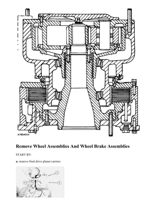
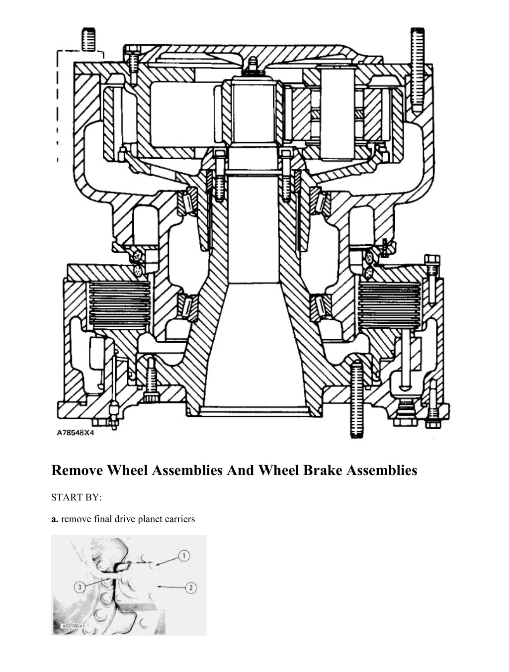
980C WHEEL LOADER 13B00733-UP (MACHINE) POWERED BY 3406 ENGINE... 2/16 Remove Wheel Assemblies And Wheel Brake Assemblies START BY: a. remove final drive planet carriers https://127.0.0.1/sisweb/sisweb/techdoc/techdoc_print_page.jsp?returnurl=/sisw... 2022/1/9
980C WHEEL LOADER 13B00733-UP (MACHINE) POWERED BY 3406 ENGINE... 3/16 1. Disconnect tube assembly (3) from the elbow. 2. Remove bolts (1), and remove housing (2), the spring and piston from the anchor plate. 3. Fasten a hoist to the wheel assembly and wheel brake assembly as shown. 4. Remove 20 nuts (5) the and washers. Remove wheel assembly and wheel brake assembly (4). The weight of the wheel assembly and wheel brake assembly is 401 kg (880 lb.). Install Wheel Assemblies And Wheel Brake Assemblies 1. Fasten a hoist to the wheel assembly and wheel brake assembly. Put wheel assembly and wheel brake assembly (1) in position on the axle housing. 2. Install the washers and nuts that hold the unit to the axle housing. Tighten the nuts to a torque of 470 40 N m (347 30 lb.ft.). https://127.0.0.1/sisweb/sisweb/techdoc/techdoc_print_page.jsp?returnurl=/sisw... 2022/1/9
980C WHEEL LOADER 13B00733-UP (MACHINE) POWERED BY 3406 ENGINE... 4/16 3. Install spring and piston (3) in housing (2). Install the housing assembly on the anchor plate. 4. Connect the tube assembly to the elbow on the housing. 5. Remove (bleed) the air from the brake system. See 980C Wheel Loader Air System And Brakes, Form No. SENR7762. END BY: a. install final drive planet carriers Disassemble Wheel Assemblies And Wheel Brake Assemblies START BY: a. remove wheel assemblies and wheel brake assemblies 1. Put the wheel assembly and wheel brake assembly in a vertical position on the floor with the wheel assembly on the top. 2. Remove retainer ring (1) from the hub assembly. https://127.0.0.1/sisweb/sisweb/techdoc/techdoc_print_page.jsp?returnurl=/sisw... 2022/1/9
https://www.ebooklibonline.com Hello dear friend! Thank you very much for reading. Enter the link into your browser. The full manual is available for immediate download. https://www.ebooklibonline.com
980C WHEEL LOADER 13B00733-UP (MACHINE) POWERED BY 3406 ENGINE... 5/16 3. Remove bolts (2). Remove plate (3) and the shims from the spindle assembly. 4. Remove hub assembly (4) from the wheel assembly. 5. Remove bushing (5) and bearing cone (6) from the hub. 6. Install three 3/8"-16 NC forged eyebolts (7) in the wheel assembly as shown. Fasten a hoist to the wheel assembly. Remove wheel assembly (8). The weight of the wheel assembly is 127 kg (280 lb.). https://127.0.0.1/sisweb/sisweb/techdoc/techdoc_print_page.jsp?returnurl=/sisw... 2022/1/9
980C WHEEL LOADER 13B00733-UP (MACHINE) POWERED BY 3406 ENGINE... 6/16 7. Turn the wheel assembly over. Remove bolts (9). Remove retainer (10) from the wheel assembly. 8. Remove Duo-Cone seal (11) from the retainer. Put an identification mark on the seal for the correct installation. 9. Remove O-ring seal (12) from the retainer. 10. Remove bearing cups (13) from the wheel assembly. https://127.0.0.1/sisweb/sisweb/techdoc/techdoc_print_page.jsp?returnurl=/sisw... 2022/1/9
980C WHEEL LOADER 13B00733-UP (MACHINE) POWERED BY 3406 ENGINE... 7/16 11. Remove Duo-Cone seal (15) from the plate. Put an identification mark on the seal for the correct installation. 12. Remove bolts (14). Remove plate (16) from the wheel brake assembly. 13. Remove O-ring seal (17) from the plate. 14. Remove nine plates (18) and eight discs (19) from the hub. 15. Remove bearing cone (20) from the spindle assembly. 16. Turn brake assembly over and put into position on wood blocks as shown. https://127.0.0.1/sisweb/sisweb/techdoc/techdoc_print_page.jsp?returnurl=/sisw... 2022/1/9
980C WHEEL LOADER 13B00733-UP (MACHINE) POWERED BY 3406 ENGINE... 8/16 17. Remove bolts (21) that hold the anchor plate to the hub. 18. Remove two studs (22) which are 180 apart from the anchor. 19. Install two 3/4"-10 NC forged eyebolts (24) in place of the studs. Fasten a hoist to the anchor plate. 20. Remove anchor plate (23), the spindle and piston from hub (25). The weight of the anchor plate, spindle and piston is 133 kg (293 lb.). 21. Remove six plugs (26) and seals from the anchor plate. Remove the O-ring seal from the spindle. https://127.0.0.1/sisweb/sisweb/techdoc/techdoc_print_page.jsp?returnurl=/sisw... 2022/1/9
980C WHEEL LOADER 13B00733-UP (MACHINE) POWERED BY 3406 ENGINE... 9/16 22. Use a bar to push the guide up, and put the spring under compression until pin (29) can be removed from the guide. Release the pressure on the guide, and remove spring (31) and guide (30) from the anchor plate. Remove the remainder of the guides and springs the same way. NOTE: On later machines use tooling (A) to compress springs (31). 23. Remove piston (28). 24. Remove seals (32) from the piston. 25. Remove four bolts (27) that hold the spindle to the anchor plate. See illustration A82587X1. 26. Install two 1/2"-13 NC forged eyebolts (33) in the spindle. Fasten a hoist to the spindle. Remove spindle (34). The weight of the spindle is 56 kg (123 lb.). 27. Remove O-ring seals (35) from the anchor plate. https://127.0.0.1/sisweb/sisweb/techdoc/techdoc_print_page.jsp?returnurl=/sisw... 2022/1/9
980C WHEEL LOADER 13B00733-UP (MACHINE) POWERED BY 3406 ENGI... 10/16 Assemble Wheel Assemblies And Wheel Brake Assemblies 1. Install O-ring seals (1) in anchor plate (2). Put a small amount of clean SAE 90 oil on the O-ring seals. 2. Install two 1/2"-13 NC forged eyebolts in the spindle as shown. Fasten a hoist to the spindle. Put spindle (3) in position in the anchor plate. 3. Install the bolts that hold the spindle to the anchor plate. Tighten the bolts to a torque of 135 15 N m (100 11 lb.ft.). 4. Install O-ring seals (4) on the piston. Put a small amount of clean SAE 90 oil on the O-ring seals. https://127.0.0.1/sisweb/sisweb/techdoc/techdoc_print_page.jsp?returnurl=/sisw... 2022/1/9
980C WHEEL LOADER 13B00733-UP (MACHINE) POWERED BY 3406 ENGI... 11/16 5. Put piston (5) in position in the anchor plate. Make sure the holes in the piston are in alignment with the holes in the anchor plate. 6. Put springs (8) and guides (7) in position in the anchor plate. Use a bar to push the guides up, and put the springs under compression until pins (6) can be installed in the guides. NOTE: On later machines use tooling (A) to compress spring (8). 7. Install O-ring seals in the plugs. Put a small amount of clean SAE 90 oil on the O-ring seals, and install plugs (11) in the anchor plate. 8. Remove two studs from the spindle 180 apart, and install two 3/4"-10 NC forged eyebolts (10) in their place. 9. Install O-ring seal (9) on the spindle. Put a small amount of clean SAE 90 oil on the O-ring seal. https://127.0.0.1/sisweb/sisweb/techdoc/techdoc_print_page.jsp?returnurl=/sisw... 2022/1/9
980C WHEEL LOADER 13B00733-UP (MACHINE) POWERED BY 3406 ENGI... 12/16 10. Fasten a hoist to the anchor plate assembly. Put anchor plate assembly (12) in position in hub (13). Install the bolts that hold the anchor plate to the hub. Tighten the bolts to a torque of 135 15 N m (100 11 lb.ft.). 11. Install bearing cone (14) on the spindle. 12. Install nine plates (15) and eight discs (16) in the hub. Start with a plate and put a disc between each plate. 13. Install O-ring seal (17) on the plate. Put a small amount of clean SAE 90 oil on the O-ring seal. https://127.0.0.1/sisweb/sisweb/techdoc/techdoc_print_page.jsp?returnurl=/sisw... 2022/1/9
980C WHEEL LOADER 13B00733-UP (MACHINE) POWERED BY 3406 ENGI... 13/16 14. Put plate (18) in position on the brake group. Install the bolts that hold it. Tighten the bolts to a torque of 135 15 N m (100 11 lb.ft.). 15. Lower the temperature of the bearing cups. Install bearing cups (19) in the wheel assembly. 16. Make sure the Duo-Cone seals are clean and dry. Make sure all metal surfaces that make contact with the seal are clean and dry. Install Duo-Cone seal (20) in the retainer with tool (C). See Remove And Install Duo-Cone Floating Seals. 17. Install the Duo-Cone seal in the brake group plate with tool (A). 18. Put retainer (21) in position on the wheel assembly. Install the bolts that hold it. Tighten the bolts to a torque of 55 7 N m (40 5 lb.ft.). https://127.0.0.1/sisweb/sisweb/techdoc/techdoc_print_page.jsp?returnurl=/sisw... 2022/1/9
980C WHEEL LOADER 13B00733-UP (MACHINE) POWERED BY 3406 ENGI... 14/16 NOTICE Do not cause damage to the Duo-Cone Seals when the wheel assembly is installed. 19. Turn the wheel assembly over, and install three 3/8"-16 NC forged eyebolts (22) as shown. Fasten a hoist to the wheel assembly. Put a small amount of clean SAE 30EP oil on the surfaces of the Duo-Cone seals that make contact with each other. Install wheel assembly (23) in the brake assembly. 20. Heat the bearing to a maximum temperature of 135 C (275 F). Install bearing cone (24) on the hub. 21. Lower the temperature of the bushing. Install bushing (25) in the hub. https://127.0.0.1/sisweb/sisweb/techdoc/techdoc_print_page.jsp?returnurl=/sisw... 2022/1/9
980C WHEEL LOADER 13B00733-UP (MACHINE) POWERED BY 3406 ENGI... 15/16 22. Install hub assembly (26) in the wheel assembly. 23. Use an outside micrometer (27), and measure the thickness of the retainer at the three small holes (28). Find the average thickness. 24. Install retainer (29) without shims on the spindle. Install three of the bolts that hold it so there are even spaces between the bolts. Turn wheel assembly slowly by hand, and tighten the bolts to a torque of 100 14 N m (74 10 lb.ft.). Loosen the bolts until the retainer is free. Tighten the bolts again to a torque of 25 7 N m (18 5 lb.ft.). 25. Use a depth micrometer (30), and measure through the three small holes in the retainer. Find the average depth. 26. Find the difference between the two average measurements in Steps 23 and 25. The difference is the gap between the end of the spindle and the retainer. https://127.0.0.1/sisweb/sisweb/techdoc/techdoc_print_page.jsp?returnurl=/sisw... 2022/1/9
980C WHEEL LOADER 13B00733-UP (MACHINE) POWERED BY 3406 ENGI... 16/16 27. Remove the retainer from the spindle. Install an amount of shims (31), the same thickness as the average gap found in Step 26 plus 0.15 mm (.006 in.). 28. Install retainer and all of the bolts. Tighten the bolts evenly to a torque of 135 14 N m (100 10 lb.ft.). NOTE: The adjustment of the wheel bearings can be done with the wheel assembly and wheel brake assembly on the machine. See the article "New Wheel Bearing Adjustment Procedure" in the May 30, 2005, Service Magazine, Form No. SEPD0786. 29. Install retainer ring (32) on the hub assembly. END BY: a. install wheel assemblies and wheel brake assemblies https://127.0.0.1/sisweb/sisweb/techdoc/techdoc_print_page.jsp?returnurl=/sisw... 2022/1/9
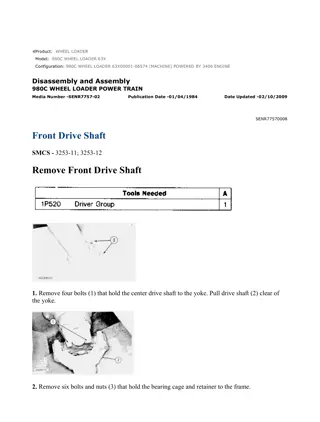
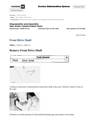
980C WHEEL LOADER 13B00733-UP (MACHINE) POWERED BY 3406 ENGINE... 1/6 Product: WHEEL LOADER Model: 980C WHEEL LOADER 13B Configuration: 980C WHEEL LOADER 13B00733-UP (MACHINE) POWERED BY 3406 ENGINE Disassembly and Assembly 980C WHEEL LOADER POWER TRAIN Media Number -SENR7757-02 Publication Date -01/04/1984 Date Updated -02/10/2009 SENR77570008 Front Drive Shaft SMCS - 3253-11; 3253-12 Remove Front Drive Shaft 1. Remove four bolts (1) that hold the center drive shaft to the yoke. Pull drive shaft (2) clear of the yoke. 2. Remove six bolts and nuts (3) that hold the bearing cage and retainer to the frame. https://127.0.0.1/sisweb/sisweb/techdoc/techdoc_print_page.jsp?returnurl=/sisw... 2022/1/9
980C WHEEL LOADER 13B00733-UP (MACHINE) POWERED BY 3406 ENGINE... 2/6 3. Remove bolt (7) and retainer (6). Remove yoke (4) from the drive shaft. 4. Remove two bolts (8), and remove retainer (5) from the bearing cage. 5. Remove lip seal (9) from the retainer. 6. Install two 3/8"-16 NC forcing screws (11) in the bearing cage. Remove bearing cage (10) and bearing from the machine. 7. Remove O-ring seal (12) from the bearing cage. https://127.0.0.1/sisweb/sisweb/techdoc/techdoc_print_page.jsp?returnurl=/sisw... 2022/1/9
980C WHEEL LOADER 13B00733-UP (MACHINE) POWERED BY 3406 ENGINE... 3/6 8. Use tooling (A) and a press to remove the bearing from the cage. 9. Remove four bolts and nuts (13) that hold the universal joint to the yoke. 10. Remove front drive shaft (15) from the machine. The weight of the front drive shaft is 29 kg (64 lb.). 11. Remove universal joint (14) from the drive shaft. Install Front Drive Shaft 1. Install universal joint (1) on the front drive shaft. Tighten the bolts to a torque of 135 15 N m (100 11 lb.ft.). 2. Put front drive shaft (2) in position on the yoke of the front differential. 3. Install the bolts that hold the universal joint to the yoke. Tighten the bolts to a torque of 135 15 N m (100 11 lb.ft.). https://127.0.0.1/sisweb/sisweb/techdoc/techdoc_print_page.jsp?returnurl=/sisw... 2022/1/9
980C WHEEL LOADER 13B00733-UP (MACHINE) POWERED BY 3406 ENGINE... 4/6 4. Use tooling (A) and a press to install the bearing in the cage. 5. Install O-ring seal (3) on the bearing cage. Put a small amount of 1P808 General Purpose Lubricant on the O-ring seal. 6. Put bearing cage (4) in position in the frame. Make sure the opening (slot) (5) in the bearing cage is toward the top as shown. 7. Install the lip seal in the retainer with tooling (A). Install the seal with the lip toward the front of the retainer. Put a small amount of 1P808 General Purpose Lubricant on the lip of the seal. https://127.0.0.1/sisweb/sisweb/techdoc/techdoc_print_page.jsp?returnurl=/sisw... 2022/1/9
Suggest: For more complete manuals. Please go to the home page. https://www.ebooklibonline.com If the above button click is invalid. Please download this document first, and then click the above link to download the complete manual. Thank you so much for reading
980C WHEEL LOADER 13B00733-UP (MACHINE) POWERED BY 3406 ENGINE... 5/6 8. Install retainer (7) on the bearing cage. Make sure grease fitting (6) is in alignment with the opening (slot) in the bearing cage. 9. Put yoke (9) in position on the drive shaft. 10. Put a small amount of 1P808 General Purpose Lubricant on the O-ring seal. Install seal (8), retainer (10) and the bolt. Tighten the bolt to a torque of 470 50 N m (347 37 lb.ft.). 11. Install the center drive shaft on the yoke. Tighten the bolts to a torque of 135 15 N m (100 11 lb.ft.). Remove Center Drive Shaft 1. Remove four bolts (3). Disconnect center drive shaft (2) and universal joint (1) from the yoke. https://127.0.0.1/sisweb/sisweb/techdoc/techdoc_print_page.jsp?returnurl=/sisw... 2022/1/9
980C WHEEL LOADER 13B00733-UP (MACHINE) POWERED BY 3406 ENGINE... 6/6 2. Remove four bolts (4). Remove center drive shaft group (2) from the machine. The weight of the center drive shaft group is 32 kg (71 lb.). 3. Remove universal joints (1) and (5) from the center drive shaft group. Install Center Drive Shaft Group 1. Install universal joints (1) on the center drive shaft group. Tighten the bolts to a torque of 135 15 N m (100 11 lb.ft.). 2. Put center drive shaft group (2) in position on the transfer gear yoke. Install the bolts that hold it. Tighten the bolts to a torque of 135 15 N m (100 11 lb.ft.). 3. Connect center drive shaft group (2) to the yoke of the front drive shaft. Install the bolts that hold it. Tighten the bolts to a torque of 135 15 N m (100 11 lb.ft.). https://127.0.0.1/sisweb/sisweb/techdoc/techdoc_print_page.jsp?returnurl=/sisw... 2022/1/9
https://www.ebooklibonline.com Hello dear friend! Thank you very much for reading. Enter the link into your browser. The full manual is available for immediate download. https://www.ebooklibonline.com

