Caterpillar Cat 963 TRACK LOADER (Prefix 18Z) Service Repair Manual Instant Download (18Z00001 and up)
Please open the website below to get the complete manualnn// n
Download Presentation

Please find below an Image/Link to download the presentation.
The content on the website is provided AS IS for your information and personal use only. It may not be sold, licensed, or shared on other websites without obtaining consent from the author. Download presentation by click this link. If you encounter any issues during the download, it is possible that the publisher has removed the file from their server.
E N D
Presentation Transcript
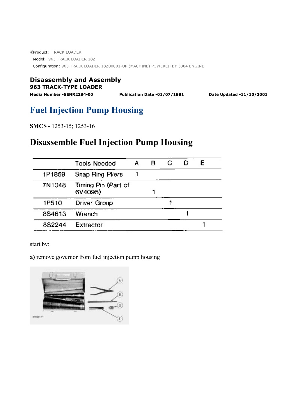
963 TRACK LOADER 18Z00001-UP (MACHINE) POWERED BY 3304 ENGINE(S... 1/9 Product: TRACK LOADER Model: 963 TRACK LOADER 18Z Configuration: 963 TRACK LOADER 18Z00001-UP (MACHINE) POWERED BY 3304 ENGINE Disassembly and Assembly 963 TRACK-TYPE LOADER Media Number -SENR2284-00 Publication Date -01/07/1981 Date Updated -11/10/2001 Fuel Injection Pump Housing SMCS - 1253-15; 1253-16 Disassemble Fuel Injection Pump Housing start by: a) remove governor from fuel injection pump housing https://127.0.0.1/sisweb/sisweb/techdoc/techdoc_print_page.jsp?returnurl=/sis... 2021/12/4
963 TRACK LOADER 18Z00001-UP (MACHINE) POWERED BY 3304 ENGINE(S... 2/9 1. Remove cover (1). 2. Install tooling (B). Engage the timing pin in the center groove of the fuel rack. Move the fuel rack in the direction of the arrow to find the center groove. 3. Install tooling (D) and remove bushing (2). 4. Install tooling (E) and remove the fuel injection pump. 5. Remove spacer (3). 6. Remove the remainder of the fuel injection pumps and spacers with Steps 2-5 done again for each fuel injection pump. NOTE: Do not mix components from fuel injection pump assemblies. https://127.0.0.1/sisweb/sisweb/techdoc/techdoc_print_page.jsp?returnurl=/sis... 2021/12/4
963 TRACK LOADER 18Z00001-UP (MACHINE) POWERED BY 3304 ENGINE(S... 3/9 7. Remove cover (4). 8. Remove fuel rack (5). 9. Use a bar magnet to remove lifter assembly (6). 10. Use tooling (A) to remove snap ring (7). https://127.0.0.1/sisweb/sisweb/techdoc/techdoc_print_page.jsp?returnurl=/sis... 2021/12/4
https://www.ebooklibonline.com Hello dear friend! Thank you very much for reading. Enter the link into your browser. The full manual is available for immediate download. https://www.ebooklibonline.com
963 TRACK LOADER 18Z00001-UP (MACHINE) POWERED BY 3304 ENGINE(S... 4/9 11. Use a plastic hammer to make camshaft (8) move out of washer (9). NOTE: Do not let the camshaft fall because the machined surfaces will be scratched. 12. Remove camshaft (8). 13. Remove rack rear bearing (10) and camshaft rear bearing (11). 14. Install location plate from tooling (B). Align the bore in the plate with the O-ring seal counterbore in the fuel injection pump housing. Make a mark for alignment. 15. Remove tooling (B). 16. Remove the rack bearing (12) and camshaft bearing (13). https://127.0.0.1/sisweb/sisweb/techdoc/techdoc_print_page.jsp?returnurl=/sis... 2021/12/4
963 TRACK LOADER 18Z00001-UP (MACHINE) POWERED BY 3304 ENGINE(S... 5/9 Assemble Fuel Injection Pump Housing NOTE: Be sure all oil passages are clear and put clean oil on all parts before assembly. https://127.0.0.1/sisweb/sisweb/techdoc/techdoc_print_page.jsp?returnurl=/sis... 2021/12/4
963 TRACK LOADER 18Z00001-UP (MACHINE) POWERED BY 3304 ENGINE(S... 6/9 1. Use tool (A) to install the camshaft rear (governor end) bearing. Install the bearing with the junction (joint) toward the top of the fuel injection pump housing. Install the bearing so it is 1.00 0.25 mm (.039 .010 in.) below the surface of the housing. 2. Use tooling (A) to install the fuel rack rear (governor end) bearing. Install the bearing so it is 7.16 0.13 mm (.282 .005 in.) below the surface of the housing. 3. Install the locator plate from tooling (B) on the drive end of the fuel injection pump housing to install the bearing for the fuel rack. Use clean grease to hold the new fuel rack bearing on the driver from tooling (C). Install the driver and bearing in the plate with the groove in the driver in alignment with the pin in the plate and use a hammer to push the bearing into position. The bearing will be installed to the correct depth when the shoulder of the driver is against the plate. 4. Remove tooling (B) from the fuel injection pump housing. The rack bearing must be installed so it is 0.25 0.25 mm (0.010 0.010 in.) below the surface of the housing. 5. Install the fuel injection pump camshaft (1) in the fuel injection pump housing. 6. Put the fuel injection pump housing on end and put a block under the camshaft. https://127.0.0.1/sisweb/sisweb/techdoc/techdoc_print_page.jsp?returnurl=/sis... 2021/12/4
963 TRACK LOADER 18Z00001-UP (MACHINE) POWERED BY 3304 ENGINE(S... 7/9 7. Put washer (2) over the end of the camshaft and use tooling (A) and (C) to push washer (2) against its seat on the camshaft. The camshaft must have 0.285 0.235 mm (0.0112 0.0093 in.) end play when the washer is pushed against cam shoulder. 8. Use tool (D) to install snap ring (3) in the groove in the camshaft. 9. Install four lifter assemblies (4) in the fuel injection pump housing with the groove in the lifter in alignment with the pin in the housing. NOTE: The four lifters are all the same and can be mixed. 10. Install fuel rack (5) in the fuel injection pump housing with the groove in the end of fuel rack in alignment with the ear (tab) of the rack bearing at the drive end of the fuel injection pump housing. https://127.0.0.1/sisweb/sisweb/techdoc/techdoc_print_page.jsp?returnurl=/sis... 2021/12/4
963 TRACK LOADER 18Z00001-UP (MACHINE) POWERED BY 3304 ENGINE(S... 8/9 11. Install timing pin from tooling (B). Engage the timing pin in the center groove of the fuel rack. Move the fuel rack in the direction of the arrow to locate the center groove. 12. Install spacer (6). 13. Put the (slot) groove (8) in the gear segment 180 away from the groove (7) in the barrel. When the fuel injection pump is installed, groove (7) must engage the dowel (9). 14. Use tool (E) to install the fuel injection pump. Installation is made easier by rotation of the cam lobe away from the lifter assembly. 15. Install O-ring seal (10). https://127.0.0.1/sisweb/sisweb/techdoc/techdoc_print_page.jsp?returnurl=/sis... 2021/12/4
963 TRACK LOADER 18Z00001-UP (MACHINE) POWERED BY 3304 ENGINE(S... 9/9 16. Install bushing (11). Tighten bushing (11) by hand until the bushing is even with the top of the housing. If installation of the bushing can not be made this far by hand, remove it. Remove the pump, put the parts in alignment again and install the bushing again. 17. Use tool (F) and a torque wrench to tighten the bushing to a torque of 190 14 N m (140 10 lb.ft.). 18. Remove tooling (B). 19. Install tooling (G) and (H) to measure total rack travel. Correct rack travel is 15.7 mm (.618 in.). A smaller measurement is an indication of wrong fuel injection pump installation. 20. Complete the installation of the remainder of fuel injection pumps as given in Steps 11-19. 21. Install cover and gasket (12). end by: a) install governor on fuel injection pump housing https://127.0.0.1/sisweb/sisweb/techdoc/techdoc_print_page.jsp?returnurl=/sis... 2021/12/4
963 TRACK LOADER 18Z00001-UP (MACHINE) POWERED BY 3304 ENGINE(S... 1/20 Product: TRACK LOADER Model: 963 TRACK LOADER 18Z Configuration: 963 TRACK LOADER 18Z00001-UP (MACHINE) POWERED BY 3304 ENGINE Disassembly and Assembly 963 TRACK-TYPE LOADER Media Number -SENR2284-00 Publication Date -01/07/1981 Date Updated -11/10/2001 Governor SMCS - 1264-15; 1264-16 Disassemble Governor start by: a) remove fuel injection pump housing and governor b) remove fuel transfer pump NOTE: If it is desired to remove only the governor so the fuel injection pump housing can be disassembled, do only Steps 1, 2, 15, 21, 25, 26, 27, 28, 31, 33, 34 and 37. https://127.0.0.1/sisweb/sisweb/techdoc/techdoc_print_page.jsp?returnurl=/sis... 2021/12/4
963 TRACK LOADER 18Z00001-UP (MACHINE) POWERED BY 3304 ENGINE(S... 2/20 1. Remove bolts (1) and remove fuel ratio control (2). 2. Remove six bolts (3), two top bolts (4), housing (5) and the gasket. 3. Remove governor spring (6), the two wave washers, one flatwasher and seat from the guide in the housing. 4. Make a mark of the position of lever (7) on shaft (8). Loosen bolt (10). Use a chisel or screwdriver to cause expansion of lever (7) so it can be removed from shaft (8). https://127.0.0.1/sisweb/sisweb/techdoc/techdoc_print_page.jsp?returnurl=/sis... 2021/12/4
963 TRACK LOADER 18Z00001-UP (MACHINE) POWERED BY 3304 ENGINE(S... 3/20 5. Remove cover assembly (9). 6. Use tooling (A) to remove seal (10) from cover (9). 7. Remove low idle adjustment screw (12) and spring (11) from the housing. 8. Remove shaft assembly (14), lever (13) and lever (15) from the housing. 9. Remove two snap rings from pins (17) and remove pins (17). Remove plates (16) and stop (18) from the shaft assembly. https://127.0.0.1/sisweb/sisweb/techdoc/techdoc_print_page.jsp?returnurl=/sis... 2021/12/4
963 TRACK LOADER 18Z00001-UP (MACHINE) POWERED BY 3304 ENGINE(S... 4/20 10. Remove pin (20), pin (19) and spring (21) from the shaft assembly. 11. Remove shaft (22) and lever (23) from the housing. 12. Remove check valve (24) if a replacement is necessary. NOTICE Remove check valve (24) only if a replacement is necessary because the check valve will be damaged during removal. 13. Remove contact (25) and body (26) for the governor dashpot adjustment screw from the housing. Remove bolts (27), cover (28) and the gasket from the housing. https://127.0.0.1/sisweb/sisweb/techdoc/techdoc_print_page.jsp?returnurl=/sis... 2021/12/4
963 TRACK LOADER 18Z00001-UP (MACHINE) POWERED BY 3304 ENGINE(S... 5/20 14. Remove seal (29) and adjustment screw (30) for high idle. 15. Remove two bolts (31), housing (32) and the gasket from the fuel injection pump housing. 16. Remove bolts (33) and torque control group (34). 17. Disassemble the torque control group and inspect the spacer, spring and insulator for damage or wear. 18. Remove bolts (36) and block (35) for the full load step from the housing. 19. Remove the bolt that holds collar (37) to bolt (39). Remove collar (37) and spring (38) from bolt (39). Remove bolt (39) from the block. 20. Remove the stop screw from collar (37) if a replacement is necessary. https://127.0.0.1/sisweb/sisweb/techdoc/techdoc_print_page.jsp?returnurl=/sis... 2021/12/4
963 TRACK LOADER 18Z00001-UP (MACHINE) POWERED BY 3304 ENGINE(S... 6/20 21. Remove bolts (41) and governor servo (40) from the fuel injection pump. 22. Remove lockring (46), seat (45), spring (broken link spring) (44) and sleeve (43) from valve (42). Remove the other lockring (46) from the groove in the center of valve (42). NOTE: The groove in the bottom of valve (42) must be in alignment with the servo body to permit removal from the fuel rack. 23. Remove valve (42), sleeve (47) and piston (49) from the governor servo. Remove the O-ring seal from sleeve (47). 24. Remove pin (48) and lever (50) from the governor servo. 25. Use tool (C) to hold spring (52) in compression so ring (51) can be removed. Spring (52) is used to put a preload on the thrust bearing for the camshaft in the fuel injection pump housing. 26. Remove ring (51) then remove tool (C). https://127.0.0.1/sisweb/sisweb/techdoc/techdoc_print_page.jsp?returnurl=/sis... 2021/12/4
963 TRACK LOADER 18Z00001-UP (MACHINE) POWERED BY 3304 ENGINE(S... 7/20 27. Remove bearing (53), sleeves (54) and spring (52) from the governor shaft. 28. Remove ring (55) and dashpot assembly (56) from the governor shaft. 29. Use tool (B) to remove snap ring (62) from seat (59). Remove ring (61) and spool (60) from seat (59). 30. Remove seat (59) from spring (58) and remove spring (58) from seat (57). 31. Remove spring (overfueling spring) (63) and riser (64) from the governor shaft. https://127.0.0.1/sisweb/sisweb/techdoc/techdoc_print_page.jsp?returnurl=/sis... 2021/12/4
963 TRACK LOADER 18Z00001-UP (MACHINE) POWERED BY 3304 ENGINE(S... 8/20 32. Remove ring (65), races (66) and bearing (67) from the riser. 33. Use a screwdriver to remove shield (68) as shown. NOTE: Make a replacement of shield (68) any time it is removed. 34. Remove bolts (69) and carrier (70) for the governor flyweights. 35. Remove dowels (71) and flyweights (73) from the carrier. 36. Remove shaft (72) from the carrier. Remove the dowel from shaft (72). https://127.0.0.1/sisweb/sisweb/techdoc/techdoc_print_page.jsp?returnurl=/sis... 2021/12/4
963 TRACK LOADER 18Z00001-UP (MACHINE) POWERED BY 3304 ENGINE(S... 9/20 37. Remove races (74) and bearing (75) from the camshaft in the fuel injection pump housing. Assemble Governor https://127.0.0.1/sisweb/sisweb/techdoc/techdoc_print_page.jsp?returnurl=/sis... 2021/12/4
Our support email: ebooklibonline@outlook.com
https://www.ebooklibonline.com Hello dear friend! Thank you very much for reading. Enter the link into your browser. The full manual is available for immediate download. https://www.ebooklibonline.com

