Caterpillar Cat 315B FM L EXCAVATOR (Prefix 7RZ) Service Repair Manual Instant Download
Please open the website below to get the complete manualnn//
Download Presentation

Please find below an Image/Link to download the presentation.
The content on the website is provided AS IS for your information and personal use only. It may not be sold, licensed, or shared on other websites without obtaining consent from the author. Download presentation by click this link. If you encounter any issues during the download, it is possible that the publisher has removed the file from their server.
E N D
Presentation Transcript
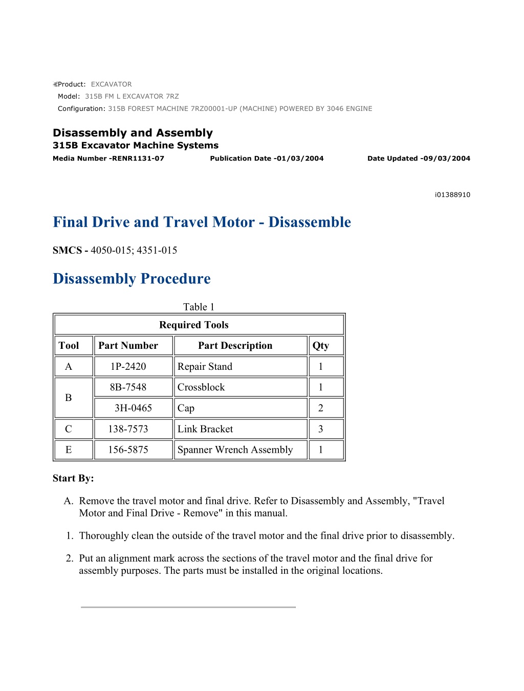
315B FOREST MACHINE 7RZ00001-UP (MACHINE) POWERED BY 3046 ENGI... 1/17 Product: EXCAVATOR Model: 315B FM L EXCAVATOR 7RZ Configuration: 315B FOREST MACHINE 7RZ00001-UP (MACHINE) POWERED BY 3046 ENGINE Disassembly and Assembly 315B Excavator Machine Systems Media Number -RENR1131-07 Publication Date -01/03/2004 Date Updated -09/03/2004 i01388910 Final Drive and Travel Motor - Disassemble SMCS - 4050-015; 4351-015 Disassembly Procedure Table 1 Required Tools Tool Part Number Part Description Qty A 1P-2420 Repair Stand 1 8B-7548 Crossblock 1 B 3H-0465 Cap 2 C 138-7573 Link Bracket 3 E 156-5875 Spanner Wrench Assembly 1 Start By: A. Remove the travel motor and final drive. Refer to Disassembly and Assembly, "Travel Motor and Final Drive - Remove" in this manual. 1. Thoroughly clean the outside of the travel motor and the final drive prior to disassembly. 2. Put an alignment mark across the sections of the travel motor and the final drive for assembly purposes. The parts must be installed in the original locations. https://127.0.0.1/sisweb/sisweb/techdoc/techdoc_print_page.jsp?returnurl=/sis... 2020/12/18
315B FOREST MACHINE 7RZ00001-UP (MACHINE) POWERED BY 3046 ENGI... 2/17 Illustration 1 g00374032 Note: A hydraulic oil sample should be obtained before any maintenance is performed in order to establish the system contaminant level. Refer to Fluid Analysis Laboratory Guide, SEBF3116, "Obtaining an Oil Sample for S O S Analysis". Refer to Operation and Maintenance Manual, "Sampling Interval and Location of Sampling Valve" for the correct location. 3. Fasten the travel motor and final drive to Tooling (A), as shown. Remove the drain plug in order to drain the oil. The capacity of the 315B final drive is 2.5 L (0.66 US gal). Drain the oil into a suitable container for storage or disposal. Illustration 2 g00374052 4. Remove nine bolts (1) and travel brake valve (2) . Personal injury can result from being struck by parts propelled by a released spring force. Make sure to wear all necessary protective equipment. https://127.0.0.1/sisweb/sisweb/techdoc/techdoc_print_page.jsp?returnurl=/sis... 2020/12/18
315B FOREST MACHINE 7RZ00001-UP (MACHINE) POWERED BY 3046 ENGI... 3/17 Follow the recommended procedure and use all recommended tooling to release the spring force. Illustration 3 g00731872 5. Remove two plugs (3) . Illustration 4 g00374056 Note: Spool assembly (6) should not be disassembled. That component is serviced as an assembly. 6. Remove spring (5) and spool assembly (6) from the travel brake valve. Remove two O-ring seals (4) and (7) from the two plugs (3) . 7. Remove four screws (8) and cap (9) . https://127.0.0.1/sisweb/sisweb/techdoc/techdoc_print_page.jsp?returnurl=/sis... 2020/12/18
https://www.ebooklibonline.com Hello dear friend! Thank you very much for reading. Enter the link into your browser. The full manual is available for immediate download. https://www.ebooklibonline.com
315B FOREST MACHINE 7RZ00001-UP (MACHINE) POWERED BY 3046 ENGI... 4/17 Illustration 5 g00374057 8. Remove O-ring seal (10), spring (11), retainer (12), and spool (13) from the travel brake valve. Illustration 6 g00374058 9. Remove two screws (14) and cap (15) . Illustration 7 g00374059 https://127.0.0.1/sisweb/sisweb/techdoc/techdoc_print_page.jsp?returnurl=/sis... 2020/12/18
315B FOREST MACHINE 7RZ00001-UP (MACHINE) POWERED BY 3046 ENGI... 5/17 10. Remove O-ring seal (18) from the cap. Remove spring (17) and retainer (16) from the travel brake valve. Illustration 8 g00731225 11. Remove eight springs (34) from brake piston (20) . 12. Remove port plate (20a) . Illustration 9 g00374061 13. Install Tooling (B), as shown. a. Apply shop air pressure of approximately 525 kPa (76 psi) to brake release port (Y) . b. Brake piston (20) will move out of the travel motor body. c. Remove brake piston (20) from the travel motor body. https://127.0.0.1/sisweb/sisweb/techdoc/techdoc_print_page.jsp?returnurl=/sis... 2020/12/18
315B FOREST MACHINE 7RZ00001-UP (MACHINE) POWERED BY 3046 ENGI... 6/17 Illustration 10 g00731881 Illustration 11 g00730242 14. Remove O-ring seals (21) and (23) and backup rings (22) and (24) from brake piston (20) . https://127.0.0.1/sisweb/sisweb/techdoc/techdoc_print_page.jsp?returnurl=/sis... 2020/12/18
315B FOREST MACHINE 7RZ00001-UP (MACHINE) POWERED BY 3046 ENGI... 7/17 Illustration 12 g00731877 15. Remove friction plate (25), four O-rings (26) and seal (27) from the travel motor body. Illustration 13 g00731901 Note: Do not permit the components of barrel assembly (28) to come apart during the removal from the travel motor body. All of the components in the barrel assembly must be reinstalled in the original locations. 16. Fasten Tooling (C) to the travel motor. Position the travel motor and final drive, as shown. Remove barrel assembly (28) from the travel motor body. Illustration 14 g00374112 17. Shoe retainer (29) and piston shoe assemblies (30) are not serviced separately. Prior to removal of the shoe retainer and the piston shoe assemblies from barrel (31), put identification marks on piston shoe assemblies (30) in order to identify the location in shoe retainer (29) and barrel (31). The piston shoe assemblies must be reinstalled in the original bores in the shoe retainer and the barrel. 18. Remove shoe retainer (29) and piston shoe assemblies (30) from barrel (31). Separate the piston shoe assemblies from the shoe retainer. https://127.0.0.1/sisweb/sisweb/techdoc/techdoc_print_page.jsp?returnurl=/sis... 2020/12/18
315B FOREST MACHINE 7RZ00001-UP (MACHINE) POWERED BY 3046 ENGI... 8/17 Illustration 15 g00374113 19. Remove bushing (33) from the barrel. Illustration 16 g00730230 Illustration 17 g00731903 https://127.0.0.1/sisweb/sisweb/techdoc/techdoc_print_page.jsp?returnurl=/sis... 2020/12/18
315B FOREST MACHINE 7RZ00001-UP (MACHINE) POWERED BY 3046 ENGI... 9/17 20. Put barrel (31) in a press. Install a suitable size drive plate on washer (36). Put a slight amount of compression on washer (38) with the press. Remove snap ring (35) and slowly release the spring compression. Remove washer (36), spring (37) and washer (38) from the barrel (31) . Illustration 18 g00374213 21. Remove swashplate (39) from the travel motor body. Illustration 19 g00374252 22. Put identification marks on two balls (40) and two pistons (41) in order to identify the location in the travel motor body. Remove two balls (40) and two pistons (41) from the travel motor body. Remove the spring that is located behind the pistons. https://127.0.0.1/sisweb/sisweb/techdoc/techdoc_print_page.jsp?returnurl=/sis... 2020/12/18
315B FOREST MACHINE 7RZ00001-UP (MACHINE) POWERED BY 3046 EN... 10/17 Illustration 20 g00731905 23. Fasten Tooling (A) to the final drive, as shown. Remove sixteen bolts (42) and the washers that hold cover (43) in place. 24. Use a soft faced hammer to break the seal between cover (43) and ring gear (44). Remove the cover. Illustration 21 g00374332 25. Remove plate (45) . https://127.0.0.1/sisweb/sisweb/techdoc/techdoc_print_page.jsp?returnurl=/sis... 2020/12/18
315B FOREST MACHINE 7RZ00001-UP (MACHINE) POWERED BY 3046 EN... 11/17 Illustration 22 g00374336 26. Remove sun gear (46) from the carrier assembly. Illustration 23 g00374358 27. Remove carrier assembly (47) by lifting straight up. Illustration 24 g00374394 28. Remove planetary gear (48) and bearing (49) from the carrier assembly. If necessary, remove race (50) and washer (51) from the carrier assembly. 29. Remove the other two planetary gears from the carrier assembly. https://127.0.0.1/sisweb/sisweb/techdoc/techdoc_print_page.jsp?returnurl=/sis... 2020/12/18
315B FOREST MACHINE 7RZ00001-UP (MACHINE) POWERED BY 3046 EN... 12/17 Illustration 25 g00374398 30. Remove sun gear (52) . Illustration 26 g00731907 31. Remove retaining ring (53) from sun gear (52) . Illustration 27 g00374401 32. Remove four bolts (54) and four plates (55) . https://127.0.0.1/sisweb/sisweb/techdoc/techdoc_print_page.jsp?returnurl=/sis... 2020/12/18
315B FOREST MACHINE 7RZ00001-UP (MACHINE) POWERED BY 3046 EN... 13/17 Illustration 28 g00374402 Illustration 29 g00374405 33. Remove planetary gear (56), bearing (57) and washer (58) from the carrier assembly. 34. Remove the other three planetary gears from the carrier assembly. Illustration 30 g00374410 https://127.0.0.1/sisweb/sisweb/techdoc/techdoc_print_page.jsp?returnurl=/sis... 2020/12/18
315B FOREST MACHINE 7RZ00001-UP (MACHINE) POWERED BY 3046 EN... 14/17 35. Remove four bolts (59) from the planetary carrier. Illustration 31 g00374411 Illustration 32 g00374854 36. Use Tooling (E) to remove nut (60) from the final drive housing. Illustration 33 g00374856 https://127.0.0.1/sisweb/sisweb/techdoc/techdoc_print_page.jsp?returnurl=/sis... 2020/12/18
315B FOREST MACHINE 7RZ00001-UP (MACHINE) POWERED BY 3046 EN... 15/17 37. Fasten Tooling (C) and a hoist to ring gear (44), as shown. Remove the ring gear from the main housing. Illustration 34 g00374853 38. Remove bearing (61) from the ring gear. Illustration 35 g00374859 39. Reposition the ring gear, as shown. Remove bearing (62) and Duo-Cone seal (63) . https://127.0.0.1/sisweb/sisweb/techdoc/techdoc_print_page.jsp?returnurl=/sis... 2020/12/18
315B FOREST MACHINE 7RZ00001-UP (MACHINE) POWERED BY 3046 EN... 16/17 Illustration 36 g00374860 40. Remove Duo-Cone seal (65) from main housing (64) . Illustration 37 g00731220 https://127.0.0.1/sisweb/sisweb/techdoc/techdoc_print_page.jsp?returnurl=/sis... 2020/12/18
315B FOREST MACHINE 7RZ00001-UP (MACHINE) POWERED BY 3046 EN... 17/17 Illustration 38 g00374861 41. Remove shaft (66) from the main housing. Remove bearing (67) from the shaft and seal (68) from the housing. https://127.0.0.1/sisweb/sisweb/techdoc/techdoc_print_page.jsp?returnurl=/sis... 2020/12/18
315B FOREST MACHINE 7RZ00001-UP (MACHINE) POWERED BY 3046 ENGI... 1/19 Product: EXCAVATOR Model: 315B FM L EXCAVATOR 7RZ Configuration: 315B FOREST MACHINE 7RZ00001-UP (MACHINE) POWERED BY 3046 ENGINE Disassembly and Assembly 315B Excavator Machine Systems Media Number -RENR1131-07 Publication Date -01/03/2004 Date Updated -09/03/2004 i01592811 Final Drive and Travel Motor - Assemble SMCS - 4050-016; 4351-016 Assembly Procedure Table 1 Required Tools Tool Part Number Part Description Qty A 1P-2420 Repair Stand 1 C 138-7573 Link Bracket 3 D 1U-6434 Duo-Cone Seal Installer 1 E 156-5875 Spanner Wrench Assembly 1 Note: Inspect all parts. If any parts are worn or damaged use new parts for replacement. The installation of used parts during reconditioning is acceptable. Reuse and salvage information is available on piston pumps. Refer to Guideline For Reusable Parts and Salvage Operations, SEBF8032, "Piston Pumps and Motors". During reconditioning, correct any conditions that might have caused the original failure. Note: O-rings, gaskets, and seals should always be replaced. A used O-ring may not have the same sealing properties as a new O-ring. Use 1U-6396 O-Ring Assembly Compound during the assembly procedure. 1. Make sure that all of the parts of the travel motor and the final drive are thoroughly clean and free of dirt and debris prior to assembly. Check the condition of all O-ring seals that are used in the travel motor and final drive. If any of the seals are worn or damaged, use new parts for replacement. Reassemble the travel motor and the final drive on Tooling (A) . https://127.0.0.1/sisweb/sisweb/techdoc/techdoc_print_page.jsp?returnurl=/sis... 2020/12/18
315B FOREST MACHINE 7RZ00001-UP (MACHINE) POWERED BY 3046 ENGI... 2/19 Illustration 1 g00731220 Illustration 2 g00374861 2. Install seal (68) in the housing. Install Bearing (67) on shaft (66). Install shaft (66) in the main housing. Note: Refer to Disassembly and Assembly, "Duo-Cone Conventional Seals - Install" in this manual. Note: The rubber seals and all of the surfaces that make contact with the seals must be clean and dry. After the installation of the seals, put clean SAE 30 oil on the contact surfaces of the metal seals. https://127.0.0.1/sisweb/sisweb/techdoc/techdoc_print_page.jsp?returnurl=/sis... 2020/12/18
315B FOREST MACHINE 7RZ00001-UP (MACHINE) POWERED BY 3046 ENGI... 3/19 Illustration 3 g00374860 Illustration 4 g00375013 3. Use Tooling (D) to install Dou-Cone seal (65) on main housing (64) . Illustration 5 g00374859 Typical example 4. Install bearing (62) on the ring gear. https://127.0.0.1/sisweb/sisweb/techdoc/techdoc_print_page.jsp?returnurl=/sis... 2020/12/18
315B FOREST MACHINE 7RZ00001-UP (MACHINE) POWERED BY 3046 ENGI... 4/19 Illustration 6 g00375015 5. Use Tooling (D) to install Dou-Cone seal (63) on the ring gear. Illustration 7 g00374853 6. Install bearing (61) in the ring gear. https://127.0.0.1/sisweb/sisweb/techdoc/techdoc_print_page.jsp?returnurl=/sis... 2020/12/18
315B FOREST MACHINE 7RZ00001-UP (MACHINE) POWERED BY 3046 ENGI... 5/19 Illustration 8 g00374856 Note: Do not damage Duo-Cone seals (63) during the assembly of the components. Do not scratch Duo-Cone seals (63) during the assembly of the components. After the installation of the ring gear on the main housing, there will be a small gap between the components. The gap is caused by the Duo-Cone seals. The gap will be eliminated during the installation of nut (60) . 7. Attach Tooling (C) to ring gear (44). Install ring gear (44) on the main housing. 8. Use the following procedure to make a preload adjustment of bearing (61) : Illustration 9 g00374411 a. Use Tooling (E) to tighten a new nut (60) to 1245 137 N m (918 101 lb ft). Rotate the hub while nut (60) is being tightened. Illustration 10 g00730220 Note: The required rolling torque for the roller bearing is 21 3 N m (15.5 2 lb ft). b. Measure the rotating torque of ring gear (44) . Note: The torque wrench must be perpendicular to the ring gear. https://127.0.0.1/sisweb/sisweb/techdoc/techdoc_print_page.jsp?returnurl=/sis... 2020/12/18
315B FOREST MACHINE 7RZ00001-UP (MACHINE) POWERED BY 3046 ENGI... 6/19 Note: The required rolling torque for the roller bearing must be measured from the center of the hub. The torque wrench is not attached to the center of the hub. The torque wrench is attached to the ring gear at the radius of the bolt hole. c. The required torque value must be recalculated in order to compensate for any change in the length of the torque wrench. The length of the torque wrench and the remaining length to the center of the hub will determine the value of rolling torque. Calculate the torque by using the following formula: (21 3 N m) X (L / (L+R)). L = the length of the arm of the torque wrench. R = the distance between the center of the hub and the wheel stud. d. Use the torque wrench in order to slowly rotate the hub. Record the amount of torque that is required to rotate the hub. If the proper torque is not achieved, nut (60) must be readjusted until the proper torque of ring gear (44) is achieved. Illustration 11 g00374410 9. Install four set screws (59) . Illustration 12 g00374405 https://127.0.0.1/sisweb/sisweb/techdoc/techdoc_print_page.jsp?returnurl=/sis... 2020/12/18
315B FOREST MACHINE 7RZ00001-UP (MACHINE) POWERED BY 3046 ENGI... 7/19 Illustration 13 g00374402 10. Install spacer (58), bearing (57), and gear (56) . 11. Repeat Step 10 for the other three gear assemblies. Illustration 14 g00374401 12. Install four plates (55) . 13. Apply 9S-3263 Thread Lock Compound to four bolts (54). Tighten the four bolts to a torque of 59 5 N m (44 4 lb ft). https://127.0.0.1/sisweb/sisweb/techdoc/techdoc_print_page.jsp?returnurl=/sis... 2020/12/18
315B FOREST MACHINE 7RZ00001-UP (MACHINE) POWERED BY 3046 ENGI... 8/19 Illustration 15 g00376820 14. Install retaining ring (53) on sun gear (52) . Illustration 16 g00374398 15. Install sun gear (52) . Illustration 17 g00730222 16. Install washer (51), race (50), bearing (49) and gear (48) on carrier assembly (47) . https://127.0.0.1/sisweb/sisweb/techdoc/techdoc_print_page.jsp?returnurl=/sis... 2020/12/18
315B FOREST MACHINE 7RZ00001-UP (MACHINE) POWERED BY 3046 ENGI... 9/19 17. Install the other two planetary gears on carrier assembly (47) . Illustration 18 g00374358 18. Install carrier assembly (47) . Illustration 19 g00374336 19. Install sun gear (46) . https://127.0.0.1/sisweb/sisweb/techdoc/techdoc_print_page.jsp?returnurl=/sis... 2020/12/18
315B FOREST MACHINE 7RZ00001-UP (MACHINE) POWERED BY 3046 EN... 10/19 Illustration 20 g00730037 20. Measure the distance from the surface of the housing to the surface of planetary gear (48) in carrier assembly (47). Record this dimension as dimension (X) . 21. If dimension (X) is between 6.22 mm (0.245 inch) and 6.91 mm (0.272 inch), then use 136- 2843 Plate (45) . 22. If dimension (X) is between 5.49 mm (0.216 inch) and 6.20 mm (0.244 inch), then use 136- 2842 Plate (45) . 23. If dimension (X) is between 4.79 mm (0.189 inch) and 5.47 mm (0.215 inch), then use 136- 2841 Plate (45) . https://127.0.0.1/sisweb/sisweb/techdoc/techdoc_print_page.jsp?returnurl=/sis... 2020/12/18
315B FOREST MACHINE 7RZ00001-UP (MACHINE) POWERED BY 3046 EN... 11/19 Illustration 21 g00374332 24. Install the appropriate plate (45) . Illustration 22 g00376813 25. Apply a bead of 1U-8846 Sealant around the machined surface of ring gear (44). Install cover (43) . 26. Install the washers and bolts (42) that hold the cover to ring gear (44). Tighten the bolts to a torque of 29 2 N m (21 1 lb ft). Illustration 23 g00374252 27. Install two balls (40) and two pistons (41) according to the marked locations in the travel motor body. https://127.0.0.1/sisweb/sisweb/techdoc/techdoc_print_page.jsp?returnurl=/sis... 2020/12/18
Suggest: If the above button click is invalid. Please download this document first, and then click the above link to download the complete manual. Thank you so much for reading
315B FOREST MACHINE 7RZ00001-UP (MACHINE) POWERED BY 3046 EN... 12/19 Illustration 24 g00374213 28. Install swashplate (39) in the travel motor body. Make sure that the machined notches in the swashplate engage the balls and the pistons. Illustration 25 g00374192 29. Install washer (38), spring (37) and washer (36) in barrel (31) . Illustration 26 g00730230 https://127.0.0.1/sisweb/sisweb/techdoc/techdoc_print_page.jsp?returnurl=/sis... 2020/12/18
https://www.ebooklibonline.com Hello dear friend! Thank you very much for reading. Enter the link into your browser. The full manual is available for immediate download. https://www.ebooklibonline.com

