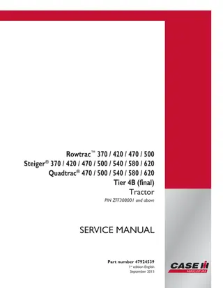
CASE IH Quadtrac 470 500 540 580 620 Tier 4B (final) Tractor Service Repair Manual Instant Download (PIN ZFF308001 and above)
Please open the website below to get the complete manualnn// n
Download Presentation

Please find below an Image/Link to download the presentation.
The content on the website is provided AS IS for your information and personal use only. It may not be sold, licensed, or shared on other websites without obtaining consent from the author. Download presentation by click this link. If you encounter any issues during the download, it is possible that the publisher has removed the file from their server.
E N D
Presentation Transcript
Rowtrac 370 / 420 / 470 / 500 Steiger 370 / 420 / 470 / 500 / 540 / 580 / 620 Quadtrac 470 / 500 / 540 / 580 / 620 Tier 4B (final) Tractor PIN ZFF308001 and above SERVICE MANUAL Printed in U.S.A. Part number 47924539 1st edition English September 2015 2015 CNH Industrial America LLC. All Rights Reserved. Case IH is a trademark registered in the United States and many other countries, owned by or licensed to CNH Industrial N.V., its subsidiaries or affiliates.
Link Product / Engine Product Market Product North America Engine QuadTrac 470 Quadtrac [ZFF308001 - ] QuadTrac 540 Quadtrac [ZFF308001 - ] QuadTrac 540 Quadtrac scraper [ZFF308001 - ] QuadTrac 580 Quadtrac [ZFF308001 - ] QuadTrac 580 Quadtrac scraper [ZFF308001 - ] QuadTrac 620 Quadtrac [ZFF308001 - ] RowTrac 370 Rowtrac [ZFF308001 - ] RowTrac 420 Rowtrac [ZFF308001 - ] RowTrac 470 Rowtrac [ZFF308001 - ] RowTrac 500 Rowtrac [ZFF308001 - ] Steiger 370 Standard wheeled [ZFF308001 - ] Steiger 370 Heavy duty wheeled [ZFF308001 - ] Steiger 420 Heavy duty wheeled [ZFF308001 - ] Steiger 470 Heavy duty wheeled [ZFF308001 - ] Steiger 470 Wheeled scraper [ZFF308001 - ] Steiger 500 Heavy duty wheeled [ZFF308001 - ] Steiger 500 Wheeled scraper [ZFF308001 - ] Steiger 500 QT Quadtrac [ZFF308001 - ] Steiger 500 QT Quadtrac scraper [ZFF308001 - ] Steiger 540 Heavy duty wheeled [ZFF308001 - ] Steiger 540 Wheeled scraper [ZFF308001 - ] Steiger 580 Heavy duty wheeled [ZFF308001 - ] Steiger 580 Wheeled scraper [ZFF308001 - ] F3HFE613D*B001 North America F3DFE613J*B001 North America F3DFE613J*B001 North America F3DFE613G*B001 North America F3DFE613G*B001 North America F3DFE613F*B001 North America F2CFE614A*B North America F3HFE613G*B001 North America F3HFE613D*B001 North America F3HFE613B*B001 North America F2CFE614A*B North America F2CFE614A*B North America F3HFE613G*B001 North America F3HFE613D*B001 North America F3HFE613D*B001 North America F3HFE613B*B001 North America F3HFE613B*B001 North America F3HFE613B*B001 North America F3HFE613B*B001 North America F3DFE613J*B001 North America F3DFE613J*B001 North America F3DFE613G*B001 North America F3DFE613G*B001 47924539 28/09/2015
Product Market Product North America Engine Steiger 620 Heavy duty wheeled [ZFF308001 - ] Steiger 620 Wheeled scraper [ZFF308001 - ] F3DFE613F*B001 North America F3DFE613F*B001 47924539 28/09/2015
https://www.ebooklibonline.com Hello dear friend! Thank you very much for reading. Enter the link into your browser. The full manual is available for immediate download. https://www.ebooklibonline.com
Contents INTRODUCTION Engine....................................................................................... 10 [10.001] Engine and crankcase ............................................................. 10.1 [10.216] Fuel tanks .......................................................................... 10.2 [10.202] Air cleaners and lines .............................................................. 10.3 [10.310] Aftercooler.......................................................................... 10.4 [10.400] Engine cooling system ............................................................. 10.5 [10.414] Fan and drive ...................................................................... 10.6 [10.500] Selective Catalytic Reduction (SCR) exhaust treatment........................... 10.7 Power coupling........................................................................... 19 [19.110] Flywheel damper ................................................................... 19.1 Transmission.............................................................................. 21 [21.113] Powershift transmission ............................................................ 21.1 [21.135] Powershift transmission external controls.......................................... 21.2 [21.155] Powershift transmission internal components...................................... 21.3 Front axle system ....................................................................... 25 [25.100] Powered front axle ................................................................. 25.1 [25.102] Front bevel gear set and differential ............................................... 25.2 [25.310] Final drives......................................................................... 25.3 [25.500] Front axle track yoke assembly .................................................... 25.4 Rear axle system........................................................................ 27 [27.100] Powered rear axle.................................................................. 27.1 [27.106] Rear bevel gear set and differential................................................ 27.2 [27.120] Planetary and final drives .......................................................... 27.3 [27.610] Rear axle track yoke assembly .................................................... 27.4 Power Take-Off (PTO)................................................................. 31 47924539 28/09/2015
[31.104] Rear electro-hydraulic control...................................................... 31.1 [31.110] One-speed rear Power Take-Off (PTO) ............................................ 31.2 [31.220] Gearbox............................................................................ 31.3 Brakes and controls .................................................................... 33 [33.110] Parking brake or parking lock ...................................................... 33.1 [33.202] Hydraulic service brakes ........................................................... 33.2 Hydraulic systems....................................................................... 35 [35.000] Hydraulic systems.................................................................. 35.1 [35.102] Pump control valves................................................................ 35.2 [35.105] Charge pump....................................................................... 35.3 [35.106] Variable displacement pump ....................................................... 35.4 [35.204] Remote control valves ............................................................. 35.5 [35.220] Auxiliary hydraulic pump and lines................................................. 35.6 [35.300] Reservoir, cooler, and filters........................................................ 35.7 [35.304] Combination pump units ........................................................... 35.8 [35.600] High flow hydraulics................................................................ 35.9 Hitches, drawbars, and implement couplings.................................. 37 [37.100] Drawbars and towing hitches ...................................................... 37.1 Frames and ballasting................................................................. 39 [39.100] Frame .............................................................................. 39.1 [39.110] Drawbar and hitch assembly ....................................................... 39.2 Steering..................................................................................... 41 [41.101] Steering control .................................................................... 41.1 [41.200] Hydraulic control components...................................................... 41.2 [41.206] Pump............................................................................... 41.3 Wheels...................................................................................... 44 [44.511] Front wheels........................................................................ 44.1 47924539 28/09/2015
[44.520] Rear wheels........................................................................ 44.2 Tracks and track suspension........................................................ 48 [48.100] Tracks .............................................................................. 48.1 [48.130] Track frame and driving wheels.................................................... 48.2 [48.134] Track tension units ................................................................. 48.3 [48.138] Track rollers ........................................................................ 48.4 Cab climate control..................................................................... 50 [50.104] Ventilation .......................................................................... 50.1 [50.200] Air conditioning..................................................................... 50.2 [50.300] Cab pressurizing system........................................................... 50.3 Electrical systems....................................................................... 55 [55.000] Electrical system ................................................................... 55.1 [55.100] Harnesses and connectors......................................................... 55.2 [55.301] Alternator........................................................................... 55.3 [55.302] Battery.............................................................................. 55.4 [55.010] Fuel injection system............................................................... 55.5 [55.014] Engine intake and exhaust system................................................. 55.6 [55.024] Transmission control system....................................................... 55.7 [55.045] Front axle control system .......................................................... 55.8 [55.046] Rear axle control system........................................................... 55.9 [55.048] Rear Power Take-Off (PTO) control system ..................................... 55.10 [55.050] Heating, Ventilation, and Air-Conditioning (HVAC) control system............... 55.11 [55.051] Cab Heating, Ventilation, and Air-Conditioning (HVAC) controls................. 55.12 [55.404] External lighting .................................................................. 55.13 [55.522] Cab Power Take-Off (PTO) controls ............................................. 55.14 [55.640] Electronic modules............................................................... 55.15 [55.035] Remote control valve electric control ............................................ 55.16 [55.130] Rear three-point hitch electronic control system ................................. 55.17 47924539 28/09/2015
[55.988] Selective Catalytic Reduction (SCR) electrical system .......................... 55.18 [55.DTC] FAULT CODES.................................................................. 55.19 Platform, cab, bodywork, and decals............................................. 90 [90.100] Engine hood and panels ........................................................... 90.1 [90.102] Engine shields, hood latches, and trims ........................................... 90.2 [90.124] Pneumatically-adjusted operator seat.............................................. 90.3 [90.150] Cab................................................................................. 90.4 [90.151] Cab interior......................................................................... 90.5 47924539 28/09/2015
INTRODUCTION 47924539 28/09/2015 1
INTRODUCTION Foreword - Important notice regarding equipment servicing STEIGER All repair and maintenance work listed in this manual must be carried out only by qualified dealership personnel, strictly complying with the instructions given, and using, whenever possible, the special tools. Anyone who performs repair and maintenance operations without complying with the procedures provided herein shall be responsible for any subsequent damages. The manufacturer and all the organizations of its distribution chain, including - without limitation - national, regional, or local dealers, reject any responsibility for damages caused by parts and/or components not approved by the manu- facturer, including those used for the servicing or repair of the product manufactured or marketed by the manufacturer. In any case, no warranty is given or attributed on the product manufactured or marketed by the manufacturer in case of damages caused by parts and/or components not approved by the manufacturer. The manufacturer reserves the right to make improvements in design and changes in specifications at any time without notice and without incurring any obligation to install them on units previously sold. Specifications, descriptions, and illustrative material herein are as accurate as known at time of publication but are subject to change without notice. In case of questions, refer to your CASE IH Sales and Service Networks. 47924539 28/09/2015 3
INTRODUCTION Safety rules STEIGER Personal safety This is the safety alert symbol. It is used to alert you to potential personal injury hazards. Obey all safety messages that follow this symbol to avoid possible death or injury. Throughout this manual you will find the signal words DANGER, WARNING, and CAUTION followed by special in- structions. These precautions are intended for the personal safety of you and those working with you. Read and understand all the safety messages in this manual before you operate or service the machine. DANGER indicates a hazardous situation that, if not avoided, will result in death or serious injury. WARNING indicates a hazardous situation that, if not avoided, could result in death or serious injury. CAUTION indicates a hazardous situation that, if not avoided, could result in minor or moderate injury. FAILURE TO FOLLOW DANGER, WARNING, AND CAUTION MESSAGES COULD RESULT IN DEATH OR SERIOUS INJURY. Machine safety NOTICE: Notice indicates a situation that, if not avoided, could result in machine or property damage. Throughout this manual you will find the signal word Notice followed by special instructions to prevent machine or property damage. The word Notice is used to address practices not related to personal safety. Information NOTE: Note indicates additional information that clarifies steps, procedures, or other information in this manual. Throughout this manual you will find the word Note followed by additional information about a step, procedure, or other information in the manual. The word Note is not intended to address personal safety or property damage. 47924539 28/09/2015 4
INTRODUCTION Safety rules - Ecology and the environment STEIGER Soil, air, and water quality is important for all industries and life in general. When legislation does not yet rule the treatment of some of the substances that advanced technology requires, sound judgment should govern the use and disposal of products of a chemical and petrochemical nature. Familiarize yourself with the relative legislation applicable to your country, and make sure that you understand this legislation. Where no legislation exists, obtain information from suppliers of oils, filters, batteries, fuels, anti-freeze, cleaning agents, etc., with regard to the effect of these substances on man and nature and how to safely store, use, and dispose of these substances. Helpful hints Avoid the use of cans or other inappropriate pressurized fuel delivery systems to fill tanks. Such delivery systems may cause considerable spillage. In general, avoid skin contact with all fuels, oils, acids, solvents, etc. Most of these products contain substances that may be harmful to your health. Modern oils contain additives. Do not burn contaminated fuels and or waste oils in ordinary heating systems. Avoid spillage when you drain fluids such as used engine coolant mixtures, engine oil, hydraulic fluid, brake fluid, etc. Do not mix drained brake fluids or fuels with lubricants. Store all drained fluids safely until you can dispose of the fluids in a proper way that complies with all local legislation and available resources. Do not allow coolant mixtures to get into the soil. Collect and dispose of coolant mixtures properly. The air-conditioning system contains gases that should not be released into the atmosphere. Consult an air-condi- tioning specialist or use a special extractor to recharge the system properly. Repair any leaks or defects in the engine cooling system or hydraulic system immediately. Do not increase the pressure in a pressurized circuit as this may lead to a component failure. Protect hoses during welding. Penetrating weld splatter may burn a hole or weaken hoses, allowing the loss of oils, coolant, etc. Battery recycling Batteries and electric accumulators contain several substances that can have a harmful effect on the environment if the batteries are not properly recycled after use. Improper disposal of batteries can contaminate the soil, groundwater, and waterways. CASE IH strongly recommends that you return all used batteries to a CASE IH dealer, who will dispose of the used batteries or recycle the used batteries properly. In some countries, this is a legal requirement. Mandatory battery recycling NOTE: The following requirements are mandatory in Brazil. Batteries are made of lead plates and a sulfuric acid solution. Because batteries contain heavy metals such as lead, CONAMA Resolution 401/2008 requires you to return all used batteries to the battery dealer when you replace any batteries. Do not dispose of batteries in your household garbage. Points of sale are obliged to: Accept the return of your used batteries Store the returned batteries in a suitable location Send the returned batteries to the battery manufacturer for recycling 47924539 28/09/2015 5
SERVICE MANUAL Engine QuadTrac 470 Quadtrac [ZFF308001 - ] , QuadTrac 540 Quadtrac [ZFF308001 - ] , QuadTrac 540 Quadtrac scraper [ZFF308001 - ] , QuadTrac 580 Quadtrac [ZFF308001 - ] , QuadTrac 580 Quadtrac scraper [ZFF308001 - ] , QuadTrac 620 Quadtrac [ZFF308001 - ] , RowTrac 370 Rowtrac [ZFF308001 - ] , RowTrac 420 Rowtrac [ZFF308001 - ] , RowTrac 470 Rowtrac [ZFF308001 - ] , RowTrac 500 Rowtrac [ZFF308001 - ] , Steiger 370 Heavy duty wheeled [ZFF308001 - ] , Steiger 370 Standard wheeled [ZFF308001 - ] , Steiger 420 Heavy duty wheeled [ZFF308001 - ] , Steiger 470 Heavy duty wheeled [ZFF308001 - ] , Steiger 470 Wheeled scraper [ZFF308001 - ] , Steiger 500 Heavy duty wheeled [ZFF308001 - ] , Steiger 500 QT Quadtrac [ZFF308001 - ] , Steiger 500 QT Quadtrac scraper [ZFF308001 - ] , Steiger 500 Wheeled scraper [ZFF308001 - ] , Steiger 540 Heavy duty wheeled [ZFF308001 - ] , Steiger 540 Wheeled scraper [ZFF308001 - ] , Steiger 580 Heavy duty wheeled [ZFF308001 - ] , Steiger 580 Wheeled scraper [ZFF308001 - ] , Steiger 620 Heavy duty wheeled [ZFF308001 - ] , Steiger 620 Wheeled scraper [ZFF308001 - ] 47924539 28/09/2015 10
Engine - Engine and crankcase Engine - Change fluid - Changing engine oil and filter STEIGER NOTE: Reduce to 300 hours or less if CASE IH AKCELA UNITEK NO. 1 SBL CJ-4 is not used. Changetheengineoilandfilterevery600hoursoronce a year or before storage, whichever occurs first. Your dealer has approved oil and filters. Do not use other types of oil or filters. NOTE: For best results change the oil and filter while the engine is still warm to the touch from operation (not hot). The tractor must be on a level surface. Remove the engine side shields. 9L engine 1. Remove the oil pan drain plug and drain the oil from the engine into a container. 2. After all oil has drained, install new washer 98474302 on drain plug, center washer on plug and install drain plug. Torque drain plug to 30 N m (22 lb ft). 3. Clean the area around the filter head and housing on the left side of the engine. Place a container under the oil filter and turn the filter housing counterclockwise to loosen with a 51 mm (2 in) wrench. After all oil has drained from the filter, remove the housing with filter. 1 RAIL13TR04406AA 4. InstallthenewfiltercartridgeandO-ring. Lightlyoilnew O-ring. 4. Reinstall the filter assembly onto the tractor. Do not over tighten or O-ring will leak. 2 RCPH10FWD928BAM 47924539 28/09/2015 10.1 [10.001] / 3
Engine - Engine and crankcase 5. Fill with new oil into the engine oil fill (1). NOTE: Total oil refill capacity will be determined by how completely the crankcase drains. Do not fill above the high mark on the dipstick (2) when refilling. 6. Operate the engine for five minutes at 1000 RPM. Check for oil leaks at the filter base and drain plug. 7. Stop the engine. Wait approximately five minutes for the oil to return to the oil pan. Check the oil level on the dipstick (2) and add oil if needed. 3 RAIL13TR04406AA 13L engines 1. Remove the oil pan drain plug and drain the oil from the engine into a container. 2. After all oil has drained, install new washer 98474302 on drain plug, center washer on plug and install drain plug. Torque drain plug to 30 N m (22 lb ft). 3. Place a container under the oil filter on the left side of theengine. Usea19 mm(0.75 in)sockettoopendrain on bottom of housing. This will allow oil to drain from the housing. After oil is drained, turn the filter housing counterclockwise to loosen with a 51 mm (2 in) wrench and remove the filter housing. 4 RAIL14TR00085AA 4. Install the new filter cartridge and O-ring. 4. Reinstall the filter assembly. Do not over tighten or the O-ring will leak. 5 RCPH10FWD928BAM 47924539 28/09/2015 10.1 [10.001] / 4
Engine - Engine and crankcase 5. Fill with new oil into the engine oil fill (1). NOTE: Total oil refill capacity will be determined by how completely the crankcase drains. Do not fill above the high mark on the dipstick (2) when refilling. 6. Operate the engine for five minutes at 1000 RPM. Check for oil leaks at the filter base and drain plug. 7. Stop the engine. Wait approximately five minutes for the oil to return to the oil pan. Check the oil level on the dipstick (2) and add oil if needed. 6 RAIL13TR01857AA 47924539 28/09/2015 10.1 [10.001] / 5
Engine - Engine and crankcase Engine - Remove - 9L RowTrac 370 Steiger 370 Prior operation: Hood support - Remove Row crop frame, 9L engine (90.102) 1. Disconnect the driveshaft from the engine. 1 RAIL13TR02967AA 2. Label and disconnect the heater hoses from the tubes. NOTE: Plug and cap all disconnected hoses and tubes. 2 RAIL13TR02966AA 3. Label and disconnect the two hoses for the diesel emis- sions fluid tank solenoid. 3 RAIL13TR02969AA 47924539 28/09/2015 10.1 [10.001] / 6
Engine - Engine and crankcase 4. Loosen the hose clamp (1) at the turbo. 5. Remove the air intake tube (2) from the engine. 4 RAIL13TR03051AA 6. Disconnect the power cable (1) from the starter. 7. Disconnect the wire (2) from the starter. 8. Remove the bolt (3) and disconnect the ground strap from the engine block. 5 RAIL13TR02970AA 9. Remove the left hand charged air cooler tube. NOTE: Plug and cap disconnected tubes and ports. 6 RAIL13TR02978AA 47924539 28/09/2015 10.1 [10.001] / 7
Engine - Engine and crankcase 10. Disconnect the lower radiator hose at the engine. 7 RAIL13TR02971AA 11. Attach a support strap to the cooling package frame and the chassis frame as shown to support the cooling package. 8 RAIL13TR02973AA 12. Remove the right hand charged air cooler tube. 9 RAIL13TR02972AA 47924539 28/09/2015 10.1 [10.001] / 8
Engine - Engine and crankcase 13. Remove the clamp (1) securing the upper radiator tube to the bracket on the engine. 14. Remove the upper radiator tube (2). 10 RAIL13TR02974AA 15. Cut the ties securing the harness and disconnect the harness. 11 RAIL13TR02976AA 16. Loosen the viscous drive from the shaft. NOTE: The fan pulley hub is left handed threaded. 12 RAIL13TR02979AA 47924539 28/09/2015 10.1 [10.001] / 9
Engine - Engine and crankcase 17. With the help of an assistant remove the fan out the right hand side of the machine. 13 RAIL13TR02977AA 18. Disconnecttheharnessleadtotheairconditionerhigh pressure switch (1) and the clutch activation lead (2) . 14 RAIL13TR02981AA 19. Use a breaker bar to relieve the tension on the serpen- tine belt and remove the belt from the air conditioner compressor pulley. 15 RAIL13TR02987AA 47924539 28/09/2015 10.1 [10.001] / 10
Engine - Engine and crankcase 20. Support the compressor and remove the four mount- ing bolts. 16 RAIL13TR02986AA 21. Set the compressor on the right hand front tire and secure with holding straps as shown. 17 RAIL13TR02982AA 22. Disconnect the power cable (1) from the alternator. 23. Disconnect the exciter wire (2) from the alternator. 18 RAIL13TR02983AA 47924539 28/09/2015 10.1 [10.001] / 11
Engine - Engine and crankcase 24. Disconnect the harness (1). 25. Remove the bolt (2) securing the harness to the en- gine block. 19 RAIL13TR02985AA 26. Unplug the connector (1). 27. Disconnect the main harness (2) from the engine con- troller. 28. Disconnect the cable (3) from the junction box. 29. Cut the tie (4) securing the harness and cable to- gether. 30. Move the harness (5) out from behind the junction box and the engine to stay with the chassis during the engine removal. 20 RAIL13TR02988AA 31. Remove the nut and bolt (1) securing the cable to the bracket. 32. Remove the bolts (2) securing the bracket to the en- gine block. 21 RAIL13TR02984AA 47924539 28/09/2015 10.1 [10.001] / 12
Engine - Engine and crankcase 33. Remove the bolt (1) securing the harness to the en- gine block. 34. Disconnect the fuel inlet hose (2). NOTE: Plug and cap all disconnected fuel hoses and fit- tings. 22 RAIL13TR02993AA 35. Disconnect the fuel return hose. 23 RAIL13TR02991AA 36. Remove the right and left hand hold down brackets. NOTE: Left hand side is shown. Remove both sides. 24 RAIL13TR02989AA 47924539 28/09/2015 10.1 [10.001] / 13
Engine - Engine and crankcase 37. Remove the front hold down bracket. 25 RAIL13TR02994AA 38. Attach the 4130 load rotor lifting bale or equivalent to overhead crane and engine lift brackets. NOTE: The engine lifting brackets are for vertical lifting only. Any lifting device that is not vertically in line with the lifting brackets can damage the engine rocker arm cover or cause bracket failure. 26 RAIL13TR02992AA 39. Remove the engine. 27 RAIL13TR02990AA 47924539 28/09/2015 10.1 [10.001] / 14
Engine - Engine and crankcase Engine - Install - 9L RowTrac 370 Steiger 370 1. Set the engine in place on the chassis. NOTE: The engine lifting brackets are for vertical lifting only. Any lifting device that is not vertically in line with the lifting brackets can damage the engine rocker arm cover or cause bracket failure. 1 RAIL13TR02990AA 2. Remove the 4130 load rotor lifting bale or equivalent from the engine lift brackets. 2 RAIL13TR02992AA 3. Install the front hold down bracket. 4. Torque the lower engine mount to frame bolts (1) to 90 - 107 N m (66 - 79 lb ft). 5. Torque the ISO mount nut and bolt to 160 - 220 N m (118 - 162 lb ft). 3 RAIL13TR02994AA 47924539 28/09/2015 10.1 [10.001] / 15
Engine - Engine and crankcase 6. Install the right and left hand hold down brackets. NOTE: Left hand side is shown. Install both sides. 7. Torque the bolts to 125 - 150 N m (92 - 111 lb ft). 4 RAIL13TR02989AA 8. Connect the fuel return hose. NOTE: Remove the plugs and caps from the disconnected fuel hoses and fittings. 5 RAIL13TR02991AA 9. Route the harness and secure to the engine block with the original bolt (1). 10. Connect the fuel inlet hose (2). 6 RAIL13TR02993AA 47924539 28/09/2015 10.1 [10.001] / 16
Engine - Engine and crankcase 11. Secure the bracket to the engine block (1) with the original bolts. 12. Secure the cable to the bracket with the original nut and bolt (2). 7 RAIL13TR02984AA 13. Route the harness (1) behind the junction box into it s original position. 14. Connect the cable (2) to the junction box as shown. 15. Connect the main harness (3) to the engine controller. 16. Plug in the connector (4) as shown. 17. Secure the harness and cable (5) together with a tie. 8 RAIL13TR02988AA 18. Connect the harness (1). 19. Route the harness to the top of the engine and secure with the original bolt (2). 9 RAIL13TR02985AA 47924539 28/09/2015 10.1 [10.001] / 17
Engine - Engine and crankcase 20. Connect the exciter wire (1) to the alternator. 21. Connect the power cable (2) to the alternator. 10 RAIL13TR02983AA 22. Remove the compressor from the right hand front tire and set in place on the engine. 11 RAIL13TR02982AA 23. Support the compressor, install the four mounting bolts and tighten. 12 RAIL13TR02986AA 47924539 28/09/2015 10.1 [10.001] / 18
Engine - Engine and crankcase 24. Use a breaker bar to move the belt tensioner and in- stall serpentine belt on to the air conditioner compres- sor pulley. 13 RAIL13TR02987AA 25. Connect the harness lead to the air conditioner high pressure switch (1) and the clutch activation lead (2) . 14 RAIL13TR02981AA 26. With the help from an assistant install the fan in place from the right hand side of the machine. 15 RAIL13TR02977AA 47924539 28/09/2015 10.1 [10.001] / 19
Engine - Engine and crankcase 27. Thread the viscous drive on to the shaft. NOTE: The fan pulley hub is left handed threaded. 28. Tighten the viscous drive on to the shaft. 16 RAIL13TR02979AA 29. Connect the harness and secure to the bracket with ties. 17 RAIL13TR02976AA 30. Set the upper radiator tube (1) in place. NOTE: Remove the plugs and caps from the disconnected tubes and ports. 31. Install the clamp (2) securing the upper radiator tube to the bracket on the engine. 32. Tighten the clamps (3) at the radiator and the thermo- stat housing on the engine. 18 RAIL13TR02974AA 47924539 28/09/2015 10.1 [10.001] / 20
Engine - Engine and crankcase 33. Assemble the right hand charged air cooler tube. 19 RAIL13TR02972AA 34. Remove the support strap. 20 RAIL13TR02973AA 35. Connect the lower radiator hose at the engine and tighten the clamp. 21 RAIL13TR02971AA 47924539 28/09/2015 10.1 [10.001] / 21
Engine - Engine and crankcase 36. Assemble the left hand charged air cooler tube. 22 RAIL13TR02978AA 37. Connect the ground strap (1) to the engine block. 38. Connect the wire (2) to the starter. 39. Connect the power cable (3) to the starter. 23 RAIL13TR02970AA 40. Assemble the air intake tube to the engine. 24 RAIL13TR03051AA 47924539 28/09/2015 10.1 [10.001] / 22
MORE MANUALS: https://www.ebooklibonline.com/ Suggest: If the above button click is invalid. Please download this document first, and then click the above link to download the complete manual. Thank you so much for reading
Engine - Engine and crankcase 41. Connect the two hoses for the diesel emissions fluid tank solenoid as labeled during disassembly. 25 RAIL13TR02969AA 42. Connect the heater hoses to the tubes as labeled dur- ing disassembly. 26 RAIL13TR02966AA 43. Connect the driveshaft to the engine. 44. Torque the bolts to 95 - 108 N m (70 - 80 lb ft) 27 RAIL13TR02967AA Next operation: Hood support - Install Row crop frame, 9L engine (90.102) 47924539 28/09/2015 10.1 [10.001] / 23
https://www.ebooklibonline.com Hello dear friend! Thank you very much for reading. Enter the link into your browser. The full manual is available for immediate download. https://www.ebooklibonline.com

