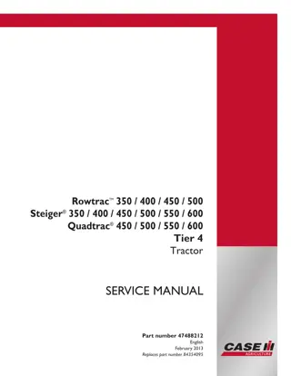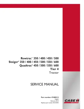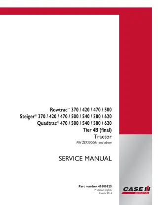
CASE IH Quadtrac 450 500 550 600 Tier 4 Tractor Service Repair Manual Instant Download
Please open the website below to get the complete manualnn// n
Download Presentation

Please find below an Image/Link to download the presentation.
The content on the website is provided AS IS for your information and personal use only. It may not be sold, licensed, or shared on other websites without obtaining consent from the author. Download presentation by click this link. If you encounter any issues during the download, it is possible that the publisher has removed the file from their server.
E N D
Presentation Transcript
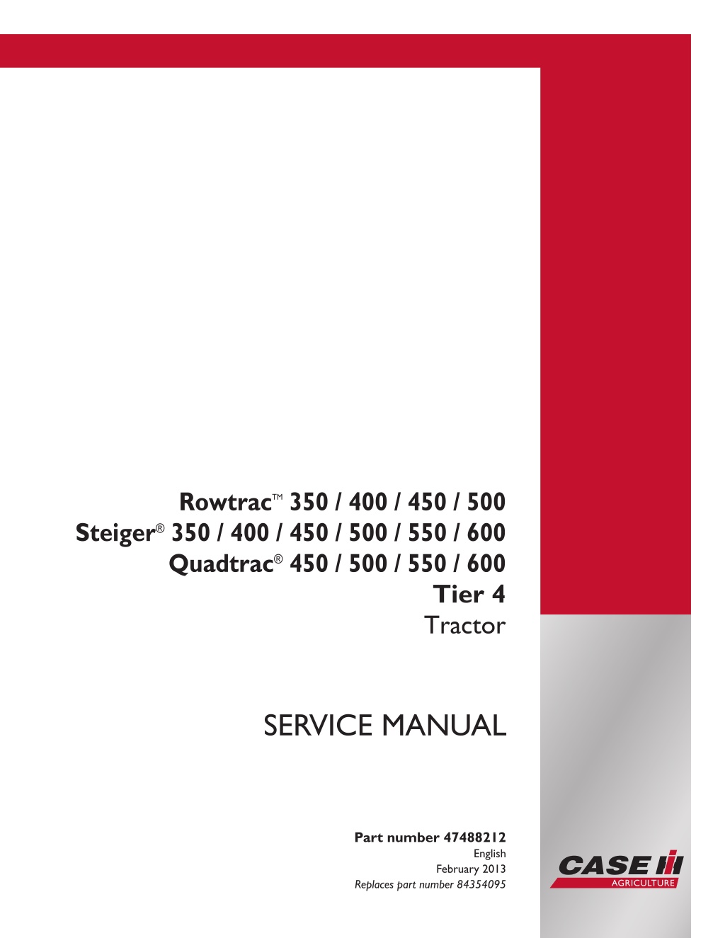
Rowtrac TM 350 / 400 / 450 / 500 Steiger 350 / 400 / 450 / 500 / 550 / 600 Quadtrac 450 / 500 / 550 / 600 Tier 4 Tractor SERVICE MANUAL Part number 47488212 Printed in U.S.A. English Copyright 2013 CNH America LLC. All Rights Reserved. Case IH is a registered trademark of CNH America LLC. Racine Wisconsin 53404 U.S.A. February 2013 Replaces part number 84354095
SERVICE MANUAL Rowtrac 350 [ZDF100001 - ] , Rowtrac 400 [ZDF100001 - ] , Rowtrac 450 [ZDF100001 - ] , Rowtrac 500 [ZDF100001 - ] , Steiger 350 [ZBF100001 - ] , Steiger 350 [ZCF100001 - ] , Steiger 350 [ZDF100001 - ] , Steiger 400 [ZBF100001 - ] , Steiger 400 [ZCF100001 - ] , Steiger 400 [ZDF100001 - ] , Steiger 450 QT [ZBF100001 - ] , Steiger 450 QT [ZCF100001 - ] , Steiger 450 QT [ZDF100001 - ] , Steiger 450 [ZBF100001 - ] , Steiger 450 [ZCF100001 - ] , Steiger 450 [ZDF100001 - ] , Steiger 500 QT [ZBF100001 - ] , Steiger 500 QT [ZCF100001 - ] , Steiger 500 QT [ZDF100001 - ] , Steiger 500 [ZBF100001 - ] , Steiger 500 [ZCF100001 - ] , Steiger 500 [ZDF100001 - ] , Steiger 550 QT [ZBF100001 - ] , Steiger 550 QT [ZCF100001 - ] , Steiger 550 QT [ZDF100001 - ] , Steiger 550 [ZBF100001 - ] , Steiger 550 [ZCF100001 - ] , Steiger 550 [ZDF100001 - ] , Steiger 600 QT [ZBF100001 - ] , Steiger 600 QT [ZCF100001 - ] , Steiger 600 QT [ZDF100001 - ] , Steiger 600 [ZBF100001 - ] , Steiger 600 [ZCF100001 - ] , Steiger 600 [ZDF100001 - ] 47488212 04/10/2013 EN
Link Product / Engine Product Market Product North America North America North America North America North America North America North America North America North America North America North America North America North America North America North America North America North America North America North America North America North America North America North America North America North America North America North America North America North America North America North America North America North America North America Engine null [ZDF100001 - ] null [ZDF100001 - ] null [ZDF100001 - ] null [ZDF100001 - ] null [ZBF100001 - ] null [ZCF100001 - ] null [ZDF100001 - ] null [ZBF100001 - ] null [ZCF100001 - ] null [ZDF100001 - ] null [ZBF100001 - ] null [ZCF100001 - ] null [ZDF100001 - ] null [ZBF100001 - ] null [ZCF100001 - ] null [ZDF100001 - ] null [ZBF100001 - ] null [ZCF100001 - ] null [ZDF100001 - ] null [ZBF100001 - ] null [ZCF100001 - ] null [ZDF100001 - ] null [ZBF100001 - ] null [ZCF100001 - ] null [ZDF100001 - ] null [ZBF100001 - ] null [ZCF100001 - ] null [ZDF100001 - ] null [ZBF100001 - ] null [ZCF100001 - ] null [ZDF100001 - ] null [ZBF100001 - ] null [ZCF100001 - ] null [ZDF100001 - ] F2CFE614A*A F3BFE613A*A001 F3BFE613A*A001 F3BFE613A*A001 F2CFE614A*A F2CFE614A*A F2CFE614A*A F3BFE613A*A001 F3BFE613A*A001 F3BFE613A*A001 F3BFE613A*A001 F3BFE613A*A001 F3BFE613A*A001 F3BFE613A*A001 F3BFE613A*A001 F3BFE613A*A001 F3BFE613A*A001 F3BFE613A*A001 F3BFE613A*A001 F3BFE613A*A001 F3BFE613A*A001 F3BFE613A*A001 F3DFE613A*A001 F3DFE613A*A001 F3DFE613A*A001 F3DFE613A*A001 F3DFE613A*A001 F3DFE613A*A001 F3DFE613A*A001 F3DFE613A*A001 F3DFE613A*A001 F3DFE613A*A001 F3DFE613A*A001 F3DFE613A*A001 47488212 04/10/2013
https://www.ebooklibonline.com Hello dear friend! Thank you very much for reading. Enter the link into your browser. The full manual is available for immediate download. https://www.ebooklibonline.com
Contents INTRODUCTION Engine....................................................................................... 10 [10.001] Engine and crankcase ............................................................. 10.1 [10.202] Air cleaners and lines .............................................................. 10.2 [10.400] Engine cooling system ............................................................. 10.3 [10.414] Fan and drive ...................................................................... 10.4 [10.500] Selective Catalytic Reduction (SCR) exhaust treatment........................... 10.5 Transmission.............................................................................. 21 [21.113] Powershift transmission ............................................................ 21.1 [21.135] Powershift transmission external controls.......................................... 21.2 [21.145] Gearbox internal components...................................................... 21.3 [21.155] Powershift transmission internal components...................................... 21.4 Front axle system ....................................................................... 25 [25.100] Powered front axle ................................................................. 25.1 [25.102] Front bevel gear set and differential ............................................... 25.2 [25.310] Final drives......................................................................... 25.3 [25.500] Front axle track yoke assembly .................................................... 25.4 Rear axle system........................................................................ 27 [27.100] Powered rear axle.................................................................. 27.1 [27.106] Rear bevel gear set and differential................................................ 27.2 [27.120] Planetary and final drives .......................................................... 27.3 [27.610] Rear axle track yoke assembly .................................................... 27.4 Power Take-Off (PTO)................................................................. 31 [31.104] Rear electro-hydraulic control...................................................... 31.1 [31.110] One-speed rear Power Take-Off (PTO) ............................................ 31.2 [31.220] Gearbox............................................................................ 31.3 47488212 04/10/2013
Brakes and controls .................................................................... 33 [33.110] Parking brake or parking lock ...................................................... 33.1 [33.202] Hydraulic service brakes ........................................................... 33.2 Hydraulic systems....................................................................... 35 [35.000] Hydraulic systems.................................................................. 35.1 [35.102] Pump control valves................................................................ 35.2 [35.105] Charge pump....................................................................... 35.3 [35.106] Variable displacement pump ....................................................... 35.4 [35.204] Remote control valves ............................................................. 35.5 [35.220] Auxiliary hydraulic pump and lines................................................. 35.6 [35.300] Reservoir, cooler, and filters........................................................ 35.7 [35.304] Combination pump units ........................................................... 35.8 [35.600] High flow hydraulics................................................................ 35.9 Hitches, drawbars, and implement couplings.................................. 37 [37.100] Drawbars and towing hitches ...................................................... 37.1 Frames and ballasting................................................................. 39 [39.100] Frame .............................................................................. 39.1 [39.110] Drawbar and hitch assembly ....................................................... 39.2 Steering..................................................................................... 41 [41.101] Steering control .................................................................... 41.1 [41.200] Hydraulic control components...................................................... 41.2 [41.206] Pump............................................................................... 41.3 Wheels...................................................................................... 44 [44.511] Front wheels........................................................................ 44.1 [44.520] Rear wheels........................................................................ 44.2 Tracks and track suspension........................................................ 48 [48.100] Tracks .............................................................................. 48.1 [48.130] Track frame and driving wheels.................................................... 48.2 47488212 04/10/2013
[48.134] Track tension units ................................................................. 48.3 [48.138] Track rollers ........................................................................ 48.4 Cab climate control..................................................................... 50 [50.104] Ventilation .......................................................................... 50.1 [50.200] Air conditioning..................................................................... 50.2 [50.300] Cab pressurizing system........................................................... 50.3 Electrical systems....................................................................... 55 [55.010] Fuel injection system............................................................... 55.1 [55.014] Engine intake and exhaust system................................................. 55.2 [55.024] Transmission control system....................................................... 55.3 [55.035] Remote control valve electric control .............................................. 55.4 [55.045] Front axle control system .......................................................... 55.5 [55.046] Rear axle control system........................................................... 55.6 [55.048] Rear Power Take-Off (PTO) control system ....................................... 55.7 [55.050] Heating, Ventilation, and Air-Conditioning (HVAC) control system................. 55.8 [55.051] Cab Heating, Ventilation, and Air-Conditioning (HVAC) controls................... 55.9 [55.100] Harnesses and connectors....................................................... 55.10 [55.130] Rear three-point hitch electronic control system ................................. 55.11 [55.301] Alternator......................................................................... 55.12 [55.302] Battery............................................................................ 55.13 [55.404] External lighting .................................................................. 55.14 [55.522] Cab Power Take-Off (PTO) controls ............................................. 55.15 [55.640] Electronic modules............................................................... 55.16 [55.988] Selective Catalytic Reduction (SCR) electrical system .......................... 55.17 [55.DTC] FAULT CODES.................................................................. 55.18 Platform, cab, bodywork, and decals............................................. 90 [90.100] Engine hood and panels ........................................................... 90.1 [90.102] Engine shields, hood latches, and trims ........................................... 90.2 47488212 04/10/2013
[90.124] Pneumatically-adjusted operator seat.............................................. 90.3 [90.150] Cab................................................................................. 90.4 [90.151] Cab interior......................................................................... 90.5 47488212 04/10/2013
INTRODUCTION 47488212 04/10/2013 1
INTRODUCTION Safety rules Steiger 350, Steiger 400, Steiger 450, Steiger 450 QT, Steiger 500, Steiger 500 QT, Steiger 550, Steiger 550 QT, Steiger 600, Steiger 600 QT, Rowtrac 350 [ZDF100001 - ] NA, Rowtrac 400 [ZDF100001 - ] NA, Rowtrac 450 [ZDF100001 - ] NA, Rowtrac 500 [ZDF100001 - ] NA Personal safety This is the safety alert symbol. It is used to alert you to potential personal injury hazards. Obey all safety messages that follow this symbol to avoid possible death or injury. Throughout this manual you will find the signal words DANGER, WARNING, and CAUTION followed by special in- structions. These precautions are intended for the personal safety of you and those working with you. Read and understand all the safety messages in this manual before you operate or service the machine. DANGER indicates a hazardous situation that, if not avoided, will result in death or serious injury. WARNING indicates a hazardous situation that, if not avoided, could result in death or serious injury. CAUTION indicates a hazardous situation that, if not avoided, could result in minor or moderate injury. FAILURE TO FOLLOW DANGER, WARNING, AND CAUTION MESSAGES COULD RESULT IN DEATH OR SERIOUS INJURY. Machine safety NOTICE: Notice indicates a situation that, if not avoided, could result in machine or property damage. Throughout this manual you will find the signal word Notice followed by special instructions to prevent machine or property damage. The word Notice is used to address practices not related to personal safety. Information NOTE: Note indicates additional information that clarifies steps, procedures, or other information in this manual. Throughout this manual you will find the word Note followed by additional information about a step, procedure, or other information in the manual. The word Note is not intended to address personal safety or property damage. 47488212 04/10/2013 3
INTRODUCTION Roll over and tip over Travel speed should be such that complete control and machine stability is maintained at all times. Where possible, avoid operating near ditches, embankments and holes. Reduce speed when turning, crossing slopes, and on rough, slick, or muddy surfaces. Do not operate the tractor on terrain outside its grade and stability limits. Operating the tractor outside its limits may result in a roll over or tip over. Observe the guidelines in this manual when going down steep hills with a load. Operating the tractor on steep grades may result in a machine overturn. It is the operator s responsibility to make a judgment if weather, road or ground conditions permit safe operation on a hillside, ramp, ditch or rough ground. Use caution when operating the machine on slopes. Raised equipment, full tanks and other loads can change the center of gravity of the machine. The machine can tip or roll over when near ditches and embankments or uneven surfaces. Do not operate the tractor near or on the soft shoulders of canals, brooks, other waterways or banks which are un- dermined by rodents. The tractor may sink sideways and roll over. Do not operate the tractor on poorly constructed or underrated ramps. The ramps may collapse and cause the tractor to roll over. Always check the condition and rating of ramps before use. Do not operate the tractor without using the seat restraint. In the event of a roll over or tip over, the ROPS cab or ROPS structure is only fully effective if the driver remains attached to the seat. Do not operate the tractor beyond its limits of dynamic stability. High speed, abrupt maneuvers or fast and sharp cornering increase the risk of roll over. Do not use the tractor for pulling where the load may not yield for example, when pulling tree stumps. The tractor may flip over backwards if the load (stump) does not yield. Be extremely cautious when operating the tractor on forage silos without lateral concrete walls. Equip the tractor with dual wheels or use a wide track setting to improve the lateral stability of the tractor. When the load on a front-end loader or three point hitch is raised, the tractor center of gravity may shift. The tractor may roll over more easily under these conditions. The instructional seat is used only when training a new operator or when a service technician is diagnosing a me- chanical problem. In all other circumstances, do not allow anyone to occupy the seat when roading to or from the field or when operating in the field. The operator s view is seriously obstructed to the left. In the event of a roll over, the ROPS cab or structure may not provide adequate protection for the occupant of the instructional seat. 47488212 04/10/2013 15
INTRODUCTION Hydraulic system safety Hydraulic oil leaking under pressure can penetrate the skin and cause infection or other injury. To prevent personal injury: Relieve all pressure before disconnecting fluid lines. Before applying pressure, make sure all connections are tight and components are in good condition. Never use your hand to check for suspected leaks under pressure. Use a piece of cardboard or wood for this purpose. If injured by leaking fluid, seek medical attention immediately. The hydraulic hoses and fittings on your machine meet engineering specifications for the particular function. When replacing damaged, blown or worn hoses or fittings, use only manufacturer authorized service parts. Care in hydraulic hose installation is a must: Make sure pressure is relieved before starting installation procedure. DO NOT kink or twist a hose, failure may occur. Properly route the hose. Have a certified hydraulic technician install the hose. Remove air from the hydraulic system after installing any hydraulic component. DO NOT stand on or use a hose as a step. DO NOT pull or apply external forces to the hose. The hose may fail and cause injury. Keep all persons away from the working area. Mechanisms controlled by fluid power can become hazardous if a hose fails. Lifted mechanisms can fall to the ground, machine steering may fail, etc. Stay clear of a pressurized hose assembly that has blown apart. Hose fittings can be thrown off at high speed and a loose hose can whip around with great force. Hydraulic fluid can reach high temperatures. Allow fluid to cool before servicing the system. Escaping fluid under pressure may form a mist or fine spray which can flash or explode upon contact with an ignition source. Vibration can reduce hose service life. Make sure all retaining clamps and/or devices are secured. Environmental conditions can cause hose and fittings to deteriorate. Inspect hydraulic hoses periodically. Replace worn or damaged hoses and fittings. Periodically check hydraulic system for leaks or damage. Check for: Leaks at hose fittings or in hose. Damaged hoses and/or fittings. Kinked, crushed, flattened, hard blistered, heat cracked, charred, twisted, soft or loose covered hoses. Corroded or damaged fittings. Leaking ports. Excessive dirt and debris around hoses and/or fittings. Damaged or missing hose retaining clamps, guards, shields, etc. 47488212 04/10/2013 16
SERVICE MANUAL Engine Rowtrac 350 [ZDF100001 - ] , Rowtrac 400 [ZDF100001 - ] , Rowtrac 450 [ZDF100001 - ] , Rowtrac 500 [ZDF100001 - ] , Steiger 350 [ZBF100001 - ] , Steiger 350 [ZCF100001 - ] , Steiger 350 [ZDF100001 - ] , Steiger 400 [ZBF100001 - ] , Steiger 400 [ZCF100001 - ] , Steiger 400 [ZDF100001 - ] , Steiger 450 QT [ZBF100001 - ] , Steiger 450 QT [ZCF100001 - ] , Steiger 450 QT [ZDF100001 - ] , Steiger 450 [ZBF100001 - ] , Steiger 450 [ZCF100001 - ] , Steiger 450 [ZDF100001 - ] , Steiger 500 QT [ZBF100001 - ] , Steiger 500 QT [ZCF100001 - ] , Steiger 500 QT [ZDF100001 - ] , Steiger 500 [ZBF100001 - ] , Steiger 500 [ZCF100001 - ] , Steiger 500 [ZDF100001 - ] , Steiger 550 QT [ZBF100001 - ] , Steiger 550 QT [ZCF100001 - ] , Steiger 550 QT [ZDF100001 - ] , Steiger 550 [ZBF100001 - ] , Steiger 550 [ZCF100001 - ] , Steiger 550 [ZDF100001 - ] , Steiger 600 QT [ZBF100001 - ] , Steiger 600 QT [ZCF100001 - ] , Steiger 600 QT [ZDF100001 - ] , Steiger 600 [ZBF100001 - ] , Steiger 600 [ZCF100001 - ] , Steiger 600 [ZDF100001 - ] 47488212 04/10/2013 10
Engine - Engine and crankcase Engine - Remove - 9 Liter tractors Steiger 350, Rowtrac 350 [ZDF100001 - ] NA Air conditioning - Evacuate - Air conditioning system (50.200) Prior operation: Hood - Remove - Hood support frame on row crop unit (90.100) 1. Disconnect air conditioning high and low pressure hoses (1) from compressor. sending unit (2). Unplug high pressure NOTE: Cap and plug disconnected hoses and ports. 1 RCPH10FWD998BAC 2. Cut ties (1) and unplug harness (2). 2 RCPH10FWD009BBC 3. Loosen fan from hub. NOTE: Hub has left hand threads. 3 RCPH10FWD010BBC 47488212 04/10/2013 10.1 [10.001] / 3
Engine - Engine and crankcase 4. With the help of an assistant turn fan off hub. Remove out the right hand side. 4 RCPH10FWD011BBC 5. Label and disconnect heater hoses (1) and DEF/Ad- Blue solenoid hoses (2). 5 RCPH10FWD012BBC 6. Disconnect starter connections (1). Remove ground strap from engine block (2). 6 RCPH10FWD013BBC 47488212 04/10/2013 10.1 [10.001] / 4
Engine - Engine and crankcase 7. Remove left hand air to air tube (1) and lower radiator hose (2). Loosen upper radiator hose clamp (3). 7 RCPH10FWD014BBC 8. Disconnect alternator cable (1). Disconnect fuel line (2). NOTE: Plug and cap disconnected fuel line and fitting. 8 RCPH10FWD015BBC 9. Secure cooling package with support strap (1). Re- move right hand air to air tube (2) and upper radiator hose (3). 9 RCPH10FWD016BBC 47488212 04/10/2013 10.1 [10.001] / 5
Engine - Engine and crankcase 10. Disconnect fuel return line. NOTE: Plug and cap disconnected hoses and fittings. 10 RCPH10FWD017BBC 11. Disconnect drive shaft from engine. 11 RCPH10FWD018BBC 12. Remove bracket on both sides over rear engine mounts. 12 RCPH10FWD019BBC 47488212 04/10/2013 10.1 [10.001] / 6
Engine - Engine and crankcase 13. Remove front engine mount bracket. 13 RCPH10FWD021BBC 14. Attach 4130 load rotor lifting bale or equivalent. Re- move engine from tractor over left hand side rail. 14 RCPH10FWD022BBC 47488212 04/10/2013 10.1 [10.001] / 7
Engine - Engine and crankcase Engine - Install - 9 Liter tractors Steiger 350, Rowtrac 350 [ZDF100001 - ] NA 1. Attach load rotor 4130 lifting bale or equivalent to an overhead hoist and the two engine lifting brackets. In- stall isomounts, lift engine and set into tractor frame. NOTICE: The engine lifting brackets are for vertical lifting only. Any lifting device that is not vertically in line with the lifting brackets can damage the engine rocker arm cover or cause bracket failure 1 RCPH10FWD022BBC 2. Install front engine mount bracket. Torque the lower engine mount to frame bolts (1) to 90 - 107 N m (66 - 79 lbft). TorquetheISOmountnut(2)to160-220 N m (118 - 162 lb ft). 2 RCPH10FWD021BBC 3. Install rear retaining straps to both sides. Torque bolts to 125 - 150 N m (92 - 111 lb ft). . 3 RCPH10FWD020BBC 47488212 04/10/2013 10.1 [10.001] / 8
Engine - Engine and crankcase 4. Connect drive shaft to drive coupler. Torque the bolts to 95 - 108 N m (70 - 80 lb ft). 4 RCPH10FWD018BBC 5. Connect fuel return line. NOTE: Remove plug and cap from hose and fitting. 5 RCPH10FWD017BBC 6. Install upper radiator hose (1) and right hand air to air tube (2). Remove support strap (3). 6 RCPH10FWD016BBC 47488212 04/10/2013 10.1 [10.001] / 9
Engine - Engine and crankcase 7. Connect fuel line (1)and alternator cable (2). NOTE: Remove plug and cap from hose and fitting. 7 RCPH10FWD015BBC 8. Tighten upper radiator hose (1). Install lower radiator hose (2), and left hand air to air tube (3). 8 RCPH10FWD014BBC 9. Secure ground strap to engine block. (1). Connect starter cable and wire (2) to starter. 9 RCPH10FWD013BBC 47488212 04/10/2013 10.1 [10.001] / 10
Engine - Engine and crankcase 10. Connect Diesel Emission Fluid/AdBlue (DEF/Ad- Blue ) hoses (1) to solenoid and engine tubing. Connect heater hoses (2) as marked during disas- sembly. 10 RCPH10FWD012BBC 11. Install fan from right hand side of engine with the help of an assistant. NOTE: Hub has left handed thread. 11 RCPH10FWD011BBC 47488212 04/10/2013 10.1 [10.001] / 11
Engine - Engine and crankcase 12. Tighten fan assembly to hub . NOTE: Hub has left handed thread. 12 RCPH10FWD010BBC 13. Plug in harness connector (1) and tie harness lead (2) to bracket. 13 RCPH10FWD009BBC 14. Attach lifting straps as shown. Use overhead crane to set hood support frame into position. NOTE: Be sure right hand side air conditioner line is in place while lowering hood support frame into position. 14 RCPH10FWD008BBC 47488212 04/10/2013 10.1 [10.001] / 12
Engine - Engine and crankcase 15. Install and tighten bolts securing hood support frame to tractor frame on both sides. 15 RCPH10FWD007BBC 16. Secure hood support frame to cooling package frame with removed hardware. 16 RCPH10FWD005BBC 17. Connect hose (1). Install clamps (2). 17 RCPH10FWD004BBC 47488212 04/10/2013 10.1 [10.001] / 13
Engine - Engine and crankcase 18. Connect hoses (1) and tighten clamps. Install clamp (2) and bracket (3) to hood support frame. 18 RCPH10FWD003BBC 19. Assembleintaketube(1)toturboandairfilterhousing. Install clamps (2). Plug in harness to sensors (3). 19 RCPH10FWD002BBC 47488212 04/10/2013 10.1 [10.001] / 14
Engine - Engine and crankcase 20. Install clamps to hood support frame. 20 RCPH10FWD001CBC 21. Install clamps to hood support frame. 21 RCPH10FWD999BAC 47488212 04/10/2013 10.1 [10.001] / 15
Engine - Engine and crankcase 22. Connect high and low pressure hoses to compressor (1). Plug in high pressure sensor (2) to harness. NOTE: Install new O-rings and lubricate with clean com- pressor oil. 22 RCPH10FWD998BAC 23. Secure clamp (1). Plug in harness connector (2). 23 RCPH10FWD996BAC 24. Secure heater hoses and harness with clamps (1). Plug in connector to DEF/AdBlue heater solenoid (2). 24 RCPH10FWD995BAC 47488212 04/10/2013 10.1 [10.001] / 16
Engine - Engine and crankcase 25. Loose assemble section of exhaust from muffler/can- ister with clamps removed during disassembly. 25 RCPH10FWD994BAC 26. Install exhaust section (1) from turbo to newly installed section. Loose assemble clamps (2). 26 RCPH10FWD993BAC 27. Assemble clamp at turbo. Adjust sections of exhaust and tighten all clamps. 27 RCPH10FWD992BAC 47488212 04/10/2013 10.1 [10.001] / 17
Engine - Engine and crankcase 28. Connect lines for DEF/AdBlue (1) and connect har- ness to sensor (2). 28 RCPH10FWD991BAC 29. Set air intake duct in position. clamps (1)and bolts (2). Adjust and tighten. Loose assemble 29 RCPH10FWD990BAC 30. Assemble aspirator tube. Tighten clamps. 30 RCPH10FWD989BAC 47488212 04/10/2013 10.1 [10.001] / 18
Engine - Engine and crankcase 31. Assemble engine side shield support brackets. 31 RCPH10FWD988BAC 32. Fill engine with specified engine oil. 33. Remove drain hose, close petcock and fill cooling sys- tem with proper coolant. 32 RCPH10FWD987BAC 34. Connect cables to batteries and install hold down bracket. 33 RCPH10FWD934BAC 35. Start engine. Check for function and leaks. Next operation: Air conditioning - Charging - Air conditioning system (50.200) Next operation: Hood - Install - Hood support frame on row crop unit (90.100) 47488212 04/10/2013 10.1 [10.001] / 19
Engine - Engine and crankcase Engine - Remove - 13L single turbo tractors Steiger 400, Steiger 450, Steiger 450 QT, Steiger 500, Steiger 500 QT, Rowtrac 400 [ZDF100001 - ] NA, Rowtrac 450 [ZDF100001 - ] NA, Rowtrac 500 [ZDF100001 - ] NA Air conditioning - Evacuate - Air conditioning system (50.200) Prior operation: Hood - Remove - Hood support frame on row crop unit (90.100) Prior operation: Hood - Remove - Hood support frame on high power frame (90.100) 1. Disconnect harness connector (1), remove bolt (2) se- curing harness to engine and unplug connector (3) at valve. 1 RCPH10FWD905BAC 2. Label and disconnect heater hoses (1) from tubes on engine. Disconnect two hoses (2) for DEF/AdBlue sys- tem heater. NOTE: Plug and cap all disconnected hoses and tubing. 2 RCPH10FWD906BAC 3. Unplug high pressure sending unit (1). Disconnect air conditioning lines (2) from compressor. NOTE: Plug and cap disconnected lines and fittings. 3 RCPH10FWD907BAC 47488212 04/10/2013 10.1 [10.001] / 20
Engine - Engine and crankcase 4. Disconnect and plug fuel line (1) to pump (behind coolant recovery bottle) and to engine controller (2). 4 RCPH10FWD908BAC 5. Disconnect connector (1) to fuel pump, remove four nuts (on inside of frame) (2) remove bracket with re- covery bottle and fuel pump from frame. 5 RCPH10FWD909BAC 6. Remove clamp (1) and disconnect battery cable (2) from alternator. 6 RCPH10FWD910BAC 47488212 04/10/2013 10.1 [10.001] / 21
Engine - Engine and crankcase 7. Remove clamps (1) from stud on inside of frame and disconnect large harness connector (2). 7 RCPH10FWD911BAC 8. Remove ground strap from engine. 8 RCPH10FWD912BAC 9. Disconnect cable (1) and solenoid wire (2) to starter. Disconnect fuel return line (3). NOTE: Plug and cap fuel tube and hose. 9 RCPH10FWD913BAC 47488212 04/10/2013 10.1 [10.001] / 22
MORE MANUALS: https://www.ebooklibonline.com/ Suggest: If the above button click is invalid. Please download this document first, and then click the above link to download the complete manual. Thank you so much for reading
Engine - Engine and crankcase 10. Remove ties (1), unplug connector (2), and loosen fan hub (3) (left hand thread). With the help of an assistant turn fan off of hub and remove out right hand side past shroud. 10 RCPH10FWD914BAC 11. Installsupportstrapasshowntosupportcoolingpack- age when air to air and radiator tubes are removed. 11 RCPH10FWD915BAC 12. Loosen clamps and remove right hand air to air cooler tube (1) and upper radiator tube (2). NOTE: Plug and cap inlets and outlets on engine and cool- ing package. 12 RCPH10FWD916BAC 47488212 04/10/2013 10.1 [10.001] / 23
https://www.ebooklibonline.com Hello dear friend! Thank you very much for reading. Enter the link into your browser. The full manual is available for immediate download. https://www.ebooklibonline.com

