CASE IH PUMA 200 200 CVT Tractor Service Repair Manual Instant Download
Please open the website below to get the complete manualnn// n
Download Presentation

Please find below an Image/Link to download the presentation.
The content on the website is provided AS IS for your information and personal use only. It may not be sold, licensed, or shared on other websites without obtaining consent from the author. Download presentation by click this link. If you encounter any issues during the download, it is possible that the publisher has removed the file from their server.
E N D
Presentation Transcript
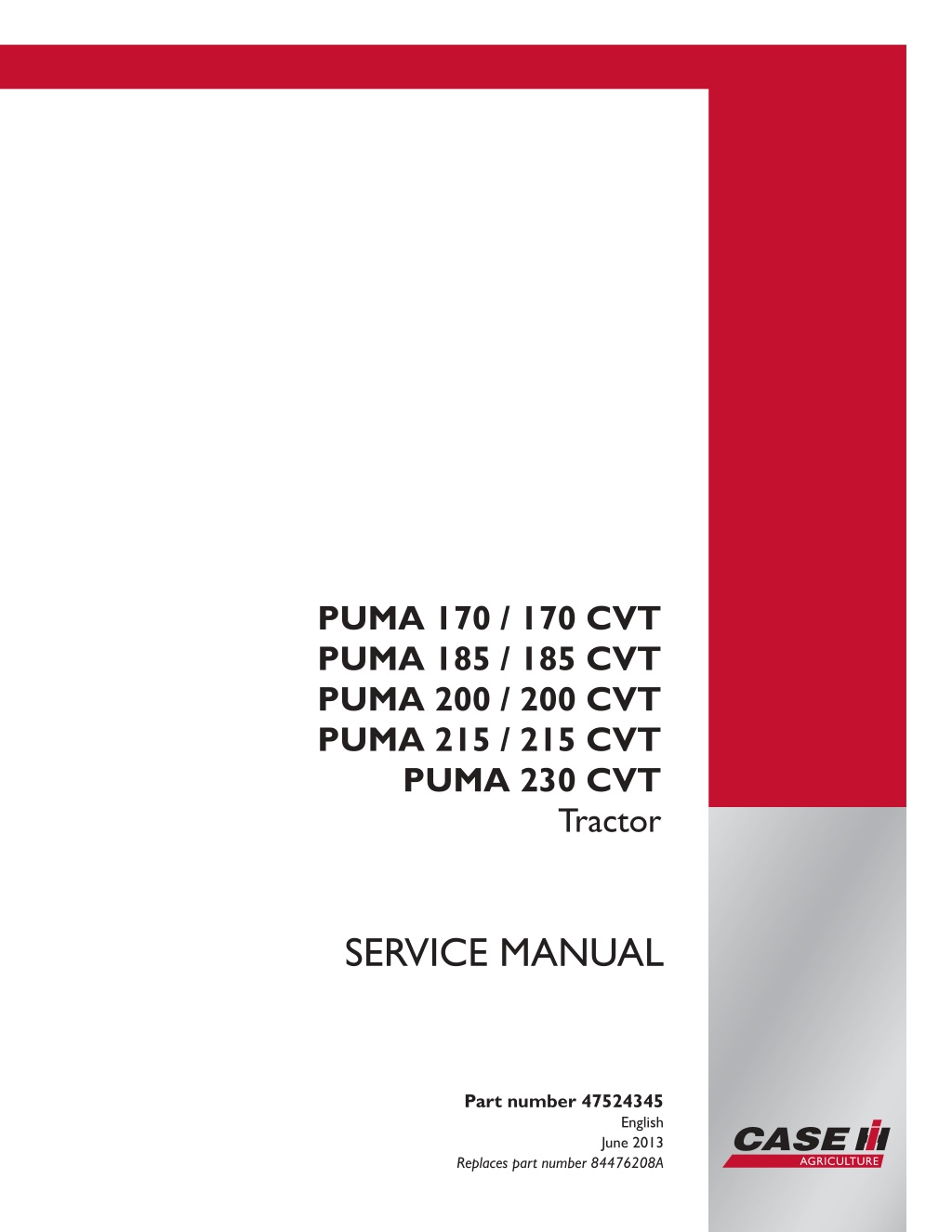
PUMA 170 / 170 CVT PUMA 185 / 185 CVT PUMA 200 / 200 CVT PUMA 215 / 215 CVT PUMA 230 CVT Tractor SERVICE MANUAL Part number 47524345 Printed in U.S.A. English June 2013 Copyright 2013 CNH America LLC. All Rights Reserved. Case IH is a registered trademark of CNH America LLC. Racine Wisconsin 53404 U.S.A. Replaces part number 84476208A
Link Product / Engine Product Market Product North America North America North America North America North America North America North America North America North America Engine PUMA 185 PUMA 200 PUMA 215 PUMA 170 CVT PUMA 185 CVT PUMA 200 CVT PUMA 215 CVT PUMA 230 CVT PUMA 170 F4DFE613K*A F4DFE613J*A F4DFE613H*A F4DFE613L*A F4DFE613K*A F4DFE613J*A F4DFE613H*A F4DFE613G*A F4DFE613L*A 47524345 23/05/2013
Contents INTRODUCTION Engine....................................................................................... 10 [10.001] Engine and crankcase ............................................................. 10.1 [10.102] Pan and covers .................................................................... 10.2 [10.216] Fuel tanks .......................................................................... 10.3 [10.210] Lift pump and lines ................................................................. 10.4 [10.218] Fuel injection system............................................................... 10.5 [10.250] Turbocharger and lines............................................................. 10.6 [10.254] Intake and exhaust manifolds and muffler ......................................... 10.7 [10.500] Selective Catalytic Reduction (SCR) exhaust treatment........................... 10.8 [10.400] Engine cooling system ............................................................. 10.9 [10.414] Fan and drive .................................................................... 10.10 [10.408] Oil cooler and lines............................................................... 10.11 Transmission.............................................................................. 21 [21.113] Powershift transmission ............................................................ 21.1 [21.155] Powershift transmission internal components...................................... 21.2 [21.160] Creeper ............................................................................ 21.3 [21.166] Overdrive........................................................................... 21.4 [21.504] Continuously Variable Transmission (CVT) ........................................ 21.5 [21.505] Continuously Variable Transmission (CVT) external controls...................... 21.6 [21.506] Continuously Variable Transmission (CVT) lubrication system .................... 21.7 [21.507] Continuously Variable Transmission (CVT) internal components.................. 21.8 [21.109] Transmission cooler and lines...................................................... 21.9 Four-Wheel Drive (4WD) system .................................................. 23 [23.202] Electro-hydraulic control ........................................................... 23.1 [23.314] Drive shaft.......................................................................... 23.2 Front axle system ....................................................................... 25 47524345 23/05/2013
https://www.ebooklibonline.com Hello dear friend! Thank you very much for reading. Enter the link into your browser. The full manual is available for immediate download. https://www.ebooklibonline.com
[25.100] Powered front axle ................................................................. 25.1 [25.102] Front bevel gear set and differential ............................................... 25.2 [25.108] Final drive hub, steering knuckles, and shafts ..................................... 25.3 [25.122] Axle suspension control............................................................ 25.4 Rear axle system........................................................................ 27 [27.100] Powered rear axle.................................................................. 27.1 [27.106] Rear bevel gear set and differential................................................ 27.2 [27.120] Planetary and final drives .......................................................... 27.3 Power Take-Off (PTO)................................................................. 31 [31.101] Rear mechanical control ........................................................... 31.1 [31.104] Rear electro-hydraulic control...................................................... 31.2 [31.114] Two-speed rear Power Take-Off (PTO) ............................................ 31.3 [31.116] Three-speed rear Power Take-Off (PTO) .......................................... 31.4 [31.119] Four-speed rear Power Take-Off (PTO)............................................ 31.5 [31.146] Front Power Take-Off (PTO) ....................................................... 31.6 Brakes and controls .................................................................... 33 [33.202] Hydraulic service brakes ........................................................... 33.1 [33.110] Parking brake or parking lock ...................................................... 33.2 [33.220] Trailer brake hydraulic control...................................................... 33.3 [33.224] Trailer brake pneumatic control .................................................... 33.4 [33.350] Anti-lock Brake System (ABS) ..................................................... 33.5 Hydraulic systems....................................................................... 35 [35.000] Hydraulic systems.................................................................. 35.1 [35.300] Reservoir, cooler, and filters........................................................ 35.2 [35.106] Variable displacement pump ....................................................... 35.3 [35.102] Pump control valves................................................................ 35.4 [35.105] Charge pump....................................................................... 35.5 [35.322] Regulated/Low pressure system................................................... 35.6 47524345 23/05/2013
[35.204] Remote control valves ............................................................. 35.7 [35.220] Auxiliary hydraulic pump and lines................................................. 35.8 [35.114] Three-point hitch control valve ..................................................... 35.9 [35.162] Front hitch cylinders and lines ................................................... 35.10 Pneumatic system ...................................................................... 36 [36.100] Pneumatic system.................................................................. 36.1 Hitches, drawbars, and implement couplings.................................. 37 [37.120] Rear three-point hitch linkage...................................................... 37.1 [37.162] Front hitch.......................................................................... 37.2 [37.110] Rear three-point hitch .............................................................. 37.3 [37.106] Automatic pickup hitch ............................................................. 37.4 Frames and ballasting................................................................. 39 [39.100] Frame .............................................................................. 39.1 Steering..................................................................................... 41 [41.101] Steering control .................................................................... 41.1 [41.106] Tie rods............................................................................. 41.2 [41.200] Hydraulic control components...................................................... 41.3 [41.216] Cylinders ........................................................................... 41.4 [41.432] Autoguidance steering ............................................................. 41.5 Wheels...................................................................................... 44 [44.511] Front wheels........................................................................ 44.1 [44.520] Rear wheels........................................................................ 44.2 Cab climate control..................................................................... 50 [50.100] Heating............................................................................. 50.1 [50.104] Ventilation .......................................................................... 50.2 [50.200] Air conditioning..................................................................... 50.3 Electrical systems....................................................................... 55 [55.610] Ground speed control .............................................................. 55.1 47524345 23/05/2013
[55.000] Electrical system ................................................................... 55.2 [55.100] Harnesses and connectors......................................................... 55.3 [55.015] Engine control system.............................................................. 55.4 [55.301] Alternator........................................................................... 55.5 [55.302] Battery.............................................................................. 55.6 [55.988] Selective Catalytic Reduction (SCR) electrical system ............................ 55.7 [55.640] Electronic modules................................................................. 55.8 [55.513] Cab transmission controls.......................................................... 55.9 [55.024] Transmission control system..................................................... 55.10 [55.020] Transmission speed sensors..................................................... 55.11 [55.021] Transmission pressure sensors.................................................. 55.12 [55.022] Transmission temperature sensors .............................................. 55.13 [55.045] Front axle control system ........................................................ 55.14 [55.048] Rear Power Take-Off (PTO) control system ..................................... 55.15 [55.049] Front Power Take-Off (PTO) control system ..................................... 55.16 [55.031] Parking brake electrical system.................................................. 55.17 [55.035] Remote control valve electric control ............................................ 55.18 [55.051] Cab Heating, Ventilation, and Air-Conditioning (HVAC) controls................. 55.19 [55.050] Heating, Ventilation, and Air-Conditioning (HVAC) control system............... 55.20 [55.047] Steering control system .......................................................... 55.21 [55.523] Cab hitch controls................................................................ 55.22 [55.130] Rear three-point hitch electronic control system ................................. 55.23 [55.911] Global Positioning System (GPS) ................................................ 55.24 [55.680] Autopilot/Autoguidance .......................................................... 55.25 [55.408] Warning indicators, alarms, and instruments .................................... 55.26 [55.350] Anti-lock Brake System (ABS) electrical system................................. 55.27 [55.032] Trailer brake electrical system ................................................... 55.28 [55.030] Service brake electrical system .................................................. 55.29 [55.DTC] FAULT CODES.................................................................. 55.30 47524345 23/05/2013
Platform, cab, bodywork, and decals............................................. 90 [90.100] Engine hood and panels ........................................................... 90.1 [90.150] Cab................................................................................. 90.2 47524345 23/05/2013
INTRODUCTION 47524345 23/05/2013 1
INTRODUCTION Advice - Important notice regarding equipment servicing All repair and maintenance work listed in this manual must be carried out only by qualified dealership personnel, strictly complying with the instructions given, and using, whenever possible, the special tools. Anyone who performs repair and maintenance operations without complying with the procedures provided herein shall be responsible for any subsequent damages. The manufacturer and all the organizations of its distribution chain, including - without limitation - national, regional, or local dealers, reject any responsibility for damages caused by parts and/or components not approved by the manu- facturer, including those used for the servicing or repair of the product manufactured or marketed by the manufacturer. In any case, no warranty is given or attributed on the product manufactured or marketed by the manufacturer in case of damages caused by parts and/or components not approved by the manufacturer. The information in this manual is up-to-date at the date of the publication. It is the policy of the manufacturer for continuous improvement. Some information could not be updated due to modifications of a technical or commercial type, or changes to the laws and regulations of different countries. In case of questions, refer to your Sales and Service Networks. 47524345 23/05/2013 3
INTRODUCTION Foreword - How to use and navigate through this manual This manual has been produced by a new technical information system. This new system is designed to deliver technical information electronically through web delivery (eTIM), DVD, and paper manuals. A coding system called SAP has been developed to link the technical information to other Product Support functions, e.g., Warranty. Technical information is written to support the maintenance and service of the functions or systems on a customer's machine. When a customer has a concern on their machine it is usually because a function or system on their ma- chine is not working at all, is not working efficiently, or is not responding correctly to their commands. When you refer to the technical information in this manual to resolve that customer's concern, you will find all the information classified using the SAP coding, according to the functions or systems on that machine. Once you have located the technical information for that function or system, you will then find all the mechanical, electrical or hydraulic devices, compo- nents, assemblies, and sub assemblies for that function or system. You will also find all the types of information that have been written for that function or system: the technical data (specifications), the functional data (how it works), the diagnostic data (fault codes and troubleshooting), and the service data (remove, install adjust, etc.). By integrating SAP coding into technical information, you will be able to search and retrieve just the right piece of technical information you need to resolve that customer's concern on his machine. This is made possible by attaching 3 categories to each piece of technical information during the authoring process. The first category is the Location, the second category is the Information Type and the third category is the Product: LOCATION - the component or function on the machine, that the piece of technical information is going to describe (e.g., Fuel tank). INFORMATION TYPE - the piece of technical information that has been written for a particular component or func- tion on the machine (e.g., Capacity would be a type of Technical Data describing the amount of fuel held by the fuel tank). PRODUCT - the model for which the piece of technical information is written. Every piece of technical information will have those three categories attached to it. You will be able to use any combi- nation of those categories to find the right piece of technical information you need to resolve that customer's concern on their machine. That information could be: the procedure for how to remove the cylinder head a table of specifications for a hydraulic pump a fault code a troubleshooting table a special tool 47524345 23/05/2013 4
INTRODUCTION Manual content This manual is divided into Sections. Each Section is then divided into Chapters. Contents pages are included at the beginning of the manual, then inside every Section and inside every Chapter. An alphabetical Index is included at the end of each Chapter. Page number references are included for every piece of technical information listed in the Chapter Contents or Chapter Index. Each Chapter is divided into four Information types: Technical Data (specifications) for all the mechanical, electrical or hydraulic devices, components, assemblies or sub-assemblies. Functional Data (how it works) for all the mechanical, electrical or hydraulic devices, components, assemblies or sub-assemblies. Diagnostic Data (fault codes, electrical and hydraulic troubleshooting) for all the mechanical, electrical or hydraulic devices, components, assemblies or sub-assemblies. Service Data (remove disassemble, assemble, install) for all the mechanical, electrical or hydraulic devices, com- ponents, assemblies or sub-assemblies. Sections Sections are grouped according to the main functions or a systems on the machine. Each Section is identified by a number (00, 35, 55, etc.). The Sections included in the manual will depend on the type and function of the machine that the manual is written for. Each Section has a Contents page listed in alphabetic/numeric order. This table illustrates which Sections could be included in a manual for a particular product. PRODUCT Tractors Vehicles with working arms: backhoes, excavators, skid steers, . Combines, forage harvesters, balers, . Seeding, planting, floating, spraying equipment, . Mounted equipment and tools, . X X X X X X X X X X X X X X X X X X X X X X X X X X X X X X X X X X X X X SECTION 00 - Maintenance 05 - Machine completion and equipment 10 - Engine 14 - Main gearbox and drive 18 - Clutch 21 - Transmission 23 - Four wheel drive (4WD) system 25 - Front axle system 27 - Rear axle system 29 - Hydrostatic drive 31 - Power Take-Off (PTO) 33 - Brakes and controls 35 - Hydraulic systems 36 - Pneumatic system 37 - Hitches, drawbars and implement couplings 39 - Frames and ballasting 41 - Steering 44 - Wheels 46 - Steering clutches 48 - Tracks and track suspension 50 - Cab climate control 55 - Electrical systems 56 - Grape harvester shaking 58 - Attachments/headers 60 - Product feeding X X X X X X X X X X X X X X X X X X X X X X X X X X X X X X X X X X X X X X X X X X X X X X X X 47524345 23/05/2013 5
INTRODUCTION 61 - Metering system 62 - Pressing - Bale formation 63 - Chemical applicators 64 - Chopping 66 - Threshing 68 - Tying/Wrapping/Twisting 69 - Bale wagons 70 - Ejection 71 - Lubrication system 72 - Separation 73 - Residue handling 74 - Cleaning 75 - Soil preparation/Finishing 76 - Secondary cleaning / Destemmer 77 - Seeding 78 - Spraying 79 - Planting 80 - Crop storage / Unloading 82 - Front loader and bucket 83 - Telescopic single arm 84 - Booms, dippers and buckets 86 - Dozer blade and arm 88 - Accessories 89 - Tools 90 - Platform, cab, bodywork and decals X X X X X X X X X X X X X X X X X X X X X X X X X X X X X X X X X X X X X X X X X 47524345 23/05/2013 6
SERVICE MANUAL Engine PUMA 170 CVT , PUMA 170 , PUMA 185 CVT , PUMA 185 , PUMA 200 CVT , PUMA 200 , PUMA 215 CVT , PUMA 215 , PUMA 230 CVT 47524345 23/05/2013 10
Engine - Engine and crankcase Engine - General specification ATTENTION: For complete service information of engine block and components refer to the relevant Engine repair manual F4DFE613L*A F4DFE613K*A F4DFE613J*A F4DFE613H*A F4DFE613G*A Engine - Special tools NAME No. TOOL 380000979 380000665 380000663 380001099 380000666 380000664 380000988 Puller for engine injection pump union gear Tool to extract crankshaft front seal Tool to extract crankshaft rear seal Injector extractor Crankshaft front seal installer Crankshaft rear seal installer Flywheel locking adaptor plate (to be used with 380000732) Engine turning tool (to be used with 380000988) Drift for camshaft bushing disassembly and reassembly Torque screwdriver for injector solenoid valve connector nut setting Connecting rod bush squaring kit Engine stand (revolving) Engine lifting brackets Large frame tractor splitting stand 380000732 380000667 380000158 99395363 380000301 380001073 380040228 47524345 23/05/2013 10.1 [10.001] / 3
Engine - Engine and crankcase Engine - Electrical test using DATAR equipment The engine controller uses the cam and crank sensor information to control the fuelling and injection timing. At initial engine start, the sensor information is used to inform the controller when to initiate first injection. The sensor infor- mation is also used by the controller to measure the actual engine speed. The crankshaft and camshaft sensors are both inductive sensors which detect the rotation of the tone wheel. The signal produced must be a clean sine-wave signal without any noise, disturbance or interferences. Channel A (Blue) Crankshaft, produces a sine-wave signal ranging 20 V. The amplitude (voltage) will change depending on the engine speed. Camshaft, produces a sine-wave signal. Channel B (Red) 1. There are three wires to the crankshaft sensor X834 (located at the front left hand side of the engine 1 SS08K075 1. Pin 1 : Earth 2. Pin 2 : Signal 3. Pin 3 : Power 2 SS08F270 2. The camshaft sensor is connected at X835 with three wires (located at the rear left hand side of the engine. 3 SS08K076 47524345 23/05/2013 10.1 [10.001] / 4
Engine - Engine and crankcase Engine - Disconnect Prior operation: Remove the battery, for further information refer to Battery - Remove (55.302) Prior operation: Drain the engine coolant, for further information refer to Engine cooling system - Drain fluid (10.400) Prior operation: Discharge the air conditioning system, for further information refer to Air conditioning - Discharging (50.200) Prior operation: Remove the selective catalytic reduction (SCR) exhaust line, for further information refer to Exhaust pipes - Remove (10.254) Prior operation: Remove the front AoH converter, for further information refer to Air-over-Hydraulic (AoH) converter - Remove (33.350) Prior operation: Remove the front wheels, for further information refer to Front wheels - Remove (44.511) WARNING Heavy objects! Lift and handle all heavy components using lift- ing equipment with adequate capacity. Always support units or parts with suitable slings or hooks. Make sure the work area is clear of all bystanders. Failure to comply could result in death or seri- ous injury. W0398A WARNING Avoid injury! Handle all parts carefully. Do not place your hands or fingers between parts. Use Personal Protective Equipment (PPE) as indicated in this manual, including protective goggles, gloves, and safety footwear. Failure to comply could result in death or seri- ous injury. W0208A 1. Using suitable lifting equipment support the front weights. 1 BAIL08CVT011AVA 47524345 23/05/2013 10.1 [10.001] / 7
Engine - Engine and crankcase 2. Disconnect and remove the front weights from the weight carrier. 2 BAIL08CVT012AVA 3. Disconnect the air conditioning hoses (1) and detach the bracket (2). NOTE: Cap all open connections to prevent contamination of the system. 3 BAIL12ABS131AVA 4. Detach the air conditioning pipe bracket from the en- gine frame. 4 BAIL11CCM027AVA 5. Remove the front AoH bracket lower bolts. 5 BAIL12ABS132AVA 47524345 23/05/2013 10.1 [10.001] / 8
Engine - Engine and crankcase 6. Detach the pipe bracket and remove the AoH bracket. 6 BAIL12ABS133AVA 7. Disconnect the brake valve supply hose (if fitted). 7 BAIL11CCM031AVA 8. Disconnect the flywheel position sensor electrical connector. 8 BAIL11CCM022AVA 9. Disconnect the steering hoses. NOTE: Make a note of the position of the hoses to aid in- stallation. 9 BAIL11CCM028AVA 47524345 23/05/2013 10.1 [10.001] / 9
Engine - Engine and crankcase 10. Disconnect the fuel supply and return lines. 10 BAIL11CCM283AVA 11. Disconnect the diff lock and suspension pipes. 11 BAIL12ABS134AVA 12. Disconnect the trailer brake air supply pipe. 12 BAIL08CVT135AVA 13. Disconnect the heater supply hose from the rear of the engine cylinder head. 13 BAIL12ABS135AVA 47524345 23/05/2013 10.1 [10.001] / 10
Engine - Engine and crankcase 14. Disconnect the steering hydraulic oil supply pipe. 14 BAIL11CCM035AVA 15. Disconnect the SCR coolant control valve electrical connector. 15 BAIL10CVT410AVB 16. Disconnect the coolant line connectors from the SCR coolant control valve. 16 BAIL10CVT412AVB 17. Detach the cab heater hose retaining bracket. 17 BAIL12ABS136AVA 47524345 23/05/2013 10.1 [10.001] / 11
Engine - Engine and crankcase 18. Disconnect the engine harness electrical connector. 18 BAIL12ABS137AVA 19. Disconnect the cab electrical connectors. 19 BAIL07APH058AVB 20. Disconnect the electrical connector and cut the cable tie. 20 BAIL12ABS138AVA 21. Disconnect the radar electrical connector (1) and re- move the radar (2). 21 BAIL12ABS139AVA 47524345 23/05/2013 10.1 [10.001] / 12
Engine - Engine and crankcase 22. Remove the flywheel speed sensor and disconnect the heater return hose. 22 BAIL12ABS140AVA 23. Disconnect the brake pipe. 23 BAIL12ABS141AVA 24. Remove the starter motor heat shield and earth. 24 BAIL12ABS142AVA 25. Remove the starter motor cover. 25 BAIL12ABS143AVA 47524345 23/05/2013 10.1 [10.001] / 13
Engine - Engine and crankcase 26. Disconnect the positive terminal (1) and bracket (2) and position to one side. 26 BAIL12ABS144AVA 27. Disconnect the starter motor electrical connector. 27 BAIL12ABS148AVA 28. Disconnect the starter motor negative cables. 28 BAIL12ABS145AVA 29. Cut the radar harness cable ties. 29 BAIL12ABS146AVA 47524345 23/05/2013 10.1 [10.001] / 14
Engine - Engine and crankcase 30. Disconnect the battery isolator switch electrical con- nector. 30 BAIL12ABS147AVA 31. Disconnect the front hitch pipes (1) and remove the bracket (2). 31 BAIL12ABS149AVA 32. Remove the front hitch pipes. 32 BAIL12ABS151AVA 33. Detach the fuse/step bracket. 33 BAIL12ABS150AVA 47524345 23/05/2013 10.1 [10.001] / 15
Engine - Engine and crankcase 34. Disconnect the oil cooler quick release couplers. For further information, refer to Oil cooler lines - Service instruction (35.300). 34 BAIL12ABS152AVA 35. Disconnect the oil cooler quick release couplers (1), removethepipebracket(2)andremovetheoilcooler pipes. For further information, refer to Oil cooler lines - Service instruction (35.300). 35 BAIL12ABS153AVA 36. Disconnect the green fuel line. 36 BAIL12ABS155AVA 37. Cut the cable ties. 37 BAIL12ABS156AVA 47524345 23/05/2013 10.1 [10.001] / 16
Engine - Engine and crankcase 38. Disconnect the diff lock supply pipe (1). Remove the pipe retaining bracket (2) and remove the diff lock pipe. 38 BAIL12ABS154AVA Vehicles with ABS 39. Detach the wiring harness (1) and disconnect the ABS speed sensor (2). 39 BAIL12ABS158AVA Vehicles with standard front axle 40. Remove the front wheel drive shaft guard and drive shaft. 40 BSD1959A 47524345 23/05/2013 10.1 [10.001] / 17
Engine - Engine and crankcase 41. Cut the cable ties and detach the wiring. 41 BAIL12ABS157AVA 42. Remove the drive shaft flange. 42 BAIL11CCM137AVA 43. 44. 45. 46. 47. Using the tractor splitting equipment 380040228 In- stallthelargerwheeledpartofthesplittingequipment under the front weight carrier. 43 BAIL12APH159AVA 47524345 23/05/2013 10.1 [10.001] / 18
Engine - Engine and crankcase 48. Position the static part of the splitting equipment un- der the transmission and secure to the transmission. Install the smaller wheeled part of the splitting equip- ment under the engine. 44 BAIL12APH160AVA 49. Connect the two pieces of the wheeled splitting gear together with the alignment bar. 45 BAIL12APH161AVA 50. Support the rear of the vehicle. 46 BAIL07APH145AVA 47524345 23/05/2013 10.1 [10.001] / 19
Engine - Engine and crankcase 51. Remove the left-hand side engine to transmission securing bolts. NOTE: Repeat this step for the right-hand side. 47 BAIL07APH146BVA 52. Remove the centre engine to transmission securing bolt (2). Remove the top left-hand engine to trans- mission securing bolt (1). NOTE: Repeat this step for the right-hand side. 48 BAIL07APH147AVA 53. Separate the engine from the transmission. 49 BAIL12APH161AVA 47524345 23/05/2013 10.1 [10.001] / 20
Engine - Engine and crankcase Engine - Connect WARNING Heavy objects! Lift and handle all heavy components using lift- ing equipment with adequate capacity. Always support units or parts with suitable slings or hooks. Make sure the work area is clear of all bystanders. Failure to comply could result in death or seri- ous injury. W0398A WARNING Avoid injury! Handle all parts carefully. Do not place your hands or fingers between parts. Use Personal Protective Equipment (PPE) as indicated in this manual, including protective goggles, gloves, and safety footwear. Failure to comply could result in death or seri- ous injury. W0208A 1. Thoroughly clean the engine to transmission mating surfaces and apply a bead of sealant. 2. Connect the transmission to the engine. 1 BAIL12APH161AVA 3. Installtheenginetotransmissioncentresecuringbolt (2). Install the engine to transmission top left-hand securing bolt (1). Tighten to 285-315 Nm ( 210-232 lb ft). NOTE: Repeat this step for the right-hand side. 2 BAIL07APH147AVA 47524345 23/05/2013 10.1 [10.001] / 21
Engine - Engine and crankcase 4. Install the left-hand side engine to transmission se- curing bolts. Tighten to 285-315 Nm ( 210-232 lb ft). NOTE: Repeat this step for the right-hand side. 3 BAIL07APH146BVA 5. Place suitable axle stands under the front axle. 6. Disconnect the two pieces of the wheeled splitting gear 380040228 and remove the alignment bar. 4 BAIL12APH161AVA 7. Remove the smaller wheeled part of the splitting equipment from under the engine. Remove the splitting equipment securing bolts from the transmission. Remove the splitting equipment from under the transmission. 5 BAIL12APH160AVA 47524345 23/05/2013 10.1 [10.001] / 22
Engine - Engine and crankcase 8. Remove the larger wheeled part of the splitting equipment from under the front weight carrier. 6 BAIL12APH159AVA 9. Remove the support from the rear of the vehicle. 7 BAIL07APH145AVA 10. 11. 12. Vehicles with standard front axle 13. Install the drive shaft flange. 8 BAIL11CCM137AVA 47524345 23/05/2013 10.1 [10.001] / 23
MORE MANUALS: https://www.ebooklibonline.com/ Suggest: If the above button click is invalid. Please download this document first, and then click the above link to download the complete manual. Thank you so much for reading
Engine - Engine and crankcase 14. Install the front wheel drive shaft and drive shaft guard. 9 BSD1959A Vehicles with ABS 15. Attach the wiring harness (1) and connect the ABS speed sensor (2). 10 BAIL12ABS158AVA All vehicles 16. Connect the differential lock supply pipe (1). Install the pipe retaining bracket (2) and install the differential lock pipe. 11 BAIL12ABS154AVA 47524345 23/05/2013 10.1 [10.001] / 24
https://www.ebooklibonline.com Hello dear friend! Thank you very much for reading. Enter the link into your browser. The full manual is available for immediate download. https://www.ebooklibonline.com


