CASE IH MXU Value and Limited Series 100, 110, 115, 125, 130, 135 Tractor Service Repair Manual Instant Download
Please open the website below to get the complete manualnn// n

Download Presentation

Please find below an Image/Link to download the presentation.
The content on the website is provided AS IS for your information and personal use only. It may not be sold, licensed, or shared on other websites without obtaining consent from the author. Download presentation by click this link. If you encounter any issues during the download, it is possible that the publisher has removed the file from their server.
E N D
Presentation Transcript
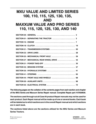
MXU VALUE AND LIMITED SERIES 100, 110, 115, 125, 130, 135, AND MAXXUM VALUE AND PRO SERIES 110, 115, 120, 125, 130, AND 140 SECTION 00 - GENERAL . . . . . . . . . . . . . . . . . . . . . . . . . . . . . . . . . . . . . . . . . . . . 3 SECTION 01 - SEPARATING THE TRACTOR . . . . . . . . . . . . . . . . . . . . . . . . . . 3 SECTION 10 - ENGINE . . . . . . . . . . . . . . . . . . . . . . . . . . . . . . . . . . . . . . . . . . . . . . 7 SECTION 18 - CLUTCH . . . . . . . . . . . . . . . . . . . . . . . . . . . . . . . . . . . . . . . . . . . . . . 19 SECTION 21 - TRANSMISSION SYSTEMS . . . . . . . . . . . . . . . . . . . . . . . . . . . . . 20 SECTION 23 - DRIVE LINES . . . . . . . . . . . . . . . . . . . . . . . . . . . . . . . . . . . . . . . . . . 28 SECTION 25 - MECHANICAL FRONT AXLE . . . . . . . . . . . . . . . . . . . . . . . . . . . 29 SECTION 27 - MECHANICAL REAR WHEEL DRIVE . . . . . . . . . . . . . . . . . . . . 33 SECTION 31 - POWER TAKE-OFF . . . . . . . . . . . . . . . . . . . . . . . . . . . . . . . . . . . . 35 SECTION 33 - BRAKING SYSTEM . . . . . . . . . . . . . . . . . . . . . . . . . . . . . . . . . . . . 37 SECTION 35 - HYDRAULIC SYSTEMS . . . . . . . . . . . . . . . . . . . . . . . . . . . . . . . . 41 SECTION 41 - STEERING . . . . . . . . . . . . . . . . . . . . . . . . . . . . . . . . . . . . . . . . . . . 65 SECTION 44 - FRONT AXLE AND WHEELS . . . . . . . . . . . . . . . . . . . . . . . . . . . 68 SECTION 50 - AUXILIARY UNITS . . . . . . . . . . . . . . . . . . . . . . . . . . . . . . . . . . . . . 69 SECTION 55 - ELECTRICAL SYSTEM . . . . . . . . . . . . . . . . . . . . . . . . . . . . . . . . . 72 The followingpages are the collationofthe contents pages from eachsection andchapter of the MXU Series and Maxxum Series Repair manual. Complete Repair part # 87659930. ThesectionsusedthroughoutallCaseIHproductRepairmanualsmaynotbeusedfor eachproduct. EachRepair manual will be made upofone or several books. Eachbook willbelabeledastowhichsectionsareintheoverallRepairmanualandwhichsections are in each book. The sections listed above are the sections utilized for the MXU Series and Maxxum Series Tractors. 87659935 Replaces 87520755 3/07 2007 CNH America LLC Printed In U.S.A.
Some sections of this Repair Manual have been revised to include the New Maxxum Value and Pro Series Models 110, 115, 120, 125, 130, and 140. Please note the following to locate new Maxxum Tractor Model Repair information: For complete engine repair information for the new Maxxum Series Tractors use Engine Repair Manual # 87661796. MostallrepairscanbecarriedoutbyfollowingtheTractor ssystemsandspecificproduct configurationsintherepairmanual.Example; 16x16 Transmission,AirConditioningand MXU Value Series Closed Center Hydraulic System. MXU Value Series Repair Information also applies to the New Maxxum Value Series Models. Where Specific Maxxum Tractor Models are not identified use the following MXU to Maxxum cross reference: Maxxum Tractor Models Maxxum 110 Maxxum 115 Maxxum 120 Maxxum 125 Maxxum 130 Maxxum 140 Use MXU tractor Model MXU 110 MXU 115 MXU 110 MXU 125 MXU 130 MXU 135 2
INFORMATION With the introduction of the Maxxum Series Tractors, controller identifications codes have changed. Also, the location of the diagnostic connector has changed. The updated Repair Manual # 87659930 does not containthenewcontrollerID s orthenewlocationof thediagnostic connector.This pageshows theMaxxum Series controller identification codes and the diagnostic connector location. NOTE: Please insert a copy of this page in the front of each Repair Manual Volume for your reference. Models covered are: MAXXUM VALUE TRACTORS 110, 115, 125 MAXXUM PRO SERIES TRACTORS 110, 120, 125, 130, 140 CONTROLLER IDENTIFICATION CODES The controller identifiers change with the introduction of the MAXXUM range of tractors, eg., Controller DA for MXU will become Controller DR for MAXXUM range. This is required to be remembered throughout this Repair Manual. See table below: Identifier MXU DA Identifier MAXXUM DR Controller Function(s) 24x24 Transmission, Electronic Draft Control, Rear PTO, Differential Lock, Four Wheel Drive 16x16 Transmission, Electronic Draft Control, Rear PTO, Differential Lock, Four Wheel Drive DB DS (Options) Front PTO, Front Hitch, Front Axle Suspension, Electronic Hydraulic Remotes DD DU Engine Control (Engine Side) Enhanced Analogue Digital Instrument Cluster (ADIC) Basic ADIC 12x12 PTO Controller -- Rear PTO, Differential Lock, Four Wheel Drive EDC7 EDC16 HA HB GA Keypad JA 2007 CNH America LLC Printed In U.S.A. 3/07 87659937
https://www.ebooklibonline.com Hello dear friend! Thank you very much for reading. Enter the link into your browser. The full manual is available for immediate download. https://www.ebooklibonline.com
CONTROLLER FUNCTIONS Electronic Module 24x24 16x16 DD(DU) Model/Type 24x24 16x16 12x12 24x24 16x16 EDC7 (EDC16) Function DA(DR) DB(DS) GA Rear PTO Differential Lock Four Wheel Drive Engine Control (vehicle side) Auto Headland Turn Sequence (HTS) Electronic Draft Control Front Suspension Front PTO Front Lift Electro-Hydraulic Remotes Transmission 24x24 Transmission 16x16 Engine Control (engine side) n n n n n n n n n n n n n n n n n n n n n n The controller type is identified by a code which is attached to each module. The code, for example, DB/DS identifies it as themodule usedon atractor with a 16x16 transmission controlling those functions highlighted in the table above. Allthemodulesonthe tractorare linkedby theCAN harnessandthisalsolinks inthe instrumentcluster, geardisplay(16x16only)anddiagnosticconnector. Refer to the system diagrams in Section 55, Chapter 1 of this repair manual for full controller details and inter connectivity. DIAGNOSTIC CONNECTORS (ADDITIONAL C PILLAR LOCATION) A single diagnostic port, 2, located behind the trim underthetransmissioncontrollevers,orontheright hand C pillar, 1, to interrogate all of the controllers is incorporated into the wiring harness. With the aid of special service tool 380000843, the port can be used to gain access to the on-board H-menu diagnostics, see Section 55, Chapter 1 of this Repair Manual for full details, to download software or to connect in more specialized diagnostic equipment such as the E.S.T. (Electronic Service Tool). C277
SECTION 00 - - GENERAL - - CHAPTER 1 SECTION 00 - - GENERAL 1 Chapter 1 - - General Information CONTENT Section Description Page General Instructions . . . . . . . . . . . . . . . . . . . . . . . . . . . . . . . . . . . . . . . . . . . . . . . . . . . . . . . . . . . . 2 00 000 Precautionary Statements . . . . . . . . . . . . . . . . . . . . . . . . . . . . . . . . . . . . . . . . . . . . . . . . . . . . . . . 3 Health and Safety . . . . . . . . . . . . . . . . . . . . . . . . . . . . . . . . . . . . . . . . . . . . . . . . . . . . . . . . . . . . . . 7 Ecology and the Environment . . . . . . . . . . . . . . . . . . . . . . . . . . . . . . . . . . . . . . . . . . . . . . . . . . 15 Product Identification . . . . . . . . . . . . . . . . . . . . . . . . . . . . . . . . . . . . . . . . . . . . . . . . . . . . . . . . . 16 International Symbols . . . . . . . . . . . . . . . . . . . . . . . . . . . . . . . . . . . . . . . . . . . . . . . . . . . . . . . . . 19 Specifications -- Limited Models . . . . . . . . . . . . . . . . . . . . . . . . . . . . . . . . . . . . . . . . . . . . . . . . 20 General Dimensions . . . . . . . . . . . . . . . . . . . . . . . . . . . . . . . . . . . . . . . . . . . . . . . . . . . . . . 20 Specifications -- Value Tractors . . . . . . . . . . . . . . . . . . . . . . . . . . . . . . . . . . . . . . . . . . . . . . . . . 27 General Dimensions . . . . . . . . . . . . . . . . . . . . . . . . . . . . . . . . . . . . . . . . . . . . . . . . . . . . . . 27 Minimum Hardware Tightening Torques . . . . . . . . . . . . . . . . . . . . . . . . . . . . . . . . . . . . . . . . . 34
SECTION 00 - - GENERAL - - CHAPTER 1 GENERAL INSTRUCTIONS 2 IMPORTANT NOTICE All maintenance and repair operations described in this manual should be carried out exclusively by authorised workshops.Allinstructionsshouldbecarefullyobservedandspecialequipmentwhereindicatedshouldbeused. Anyone who carries out service operations described without carefully observing these instructions will be directly responsible for any damage caused. NOTES FOR EQUIPMENT Equipment shown in this manual is: -- designed expressly for use on these tractors; -- necessary to make a reliable repair; -- accurately built and strictly tested to offer efficient and long--lasting working life. NOTICES The words front , rear , right hand , and left hand refer to the different parts as seen from the operator s seat oriented to the normal direction of movement of the tractor.
SECTION 00 - - GENERAL - - CHAPTER 1 3 PRECAUTIONARY STATEMENTS PERSONAL SAFETY Throughout this manual and on machine decals, you will find precautionary statements ( DANGER , WARNING ,and CAUTION )followedbyspecificinstructions.Theseprecautionsareintendedforthepersonal safety of you and those working with you. Please take the time to read them. DANGER This word DANGER indicates an immediate hazardous situation that, if not avoided, will result in death or serious injury. The color associated with Danger is RED. WARNING This word WARNING indicates a potentially hazardous situation that, if not avoided, could result in death or serious injury. The color associated with Warning is ORANGE. CAUTION This word CAUTION indicates a potentially hazardous situation that, if not avoided, may result in minor or moderate injury. It may also be used to alert against unsafe practices. The color associated with Caution is YELLOW. FAILURE TO FOLLOW THE DANGER , WARNING , AND CAUTION INSTRUCTIONS MAY RESULT IN SERIOUS BODILY INJURY OR DEATH. MACHINE SAFETY The precautionary statement ( IMPORTANT ) is followed by specific instructions. This statement is intended for machine safety. IMPORTANT: IMPORTANT: The word IMPORTANT is used to inform the reader of something he needs to know to prevent minor machine damage if a certain procedure is not followed. INFORMATION NOTE: NOTE: Instructions used to identify and present supplementary information.
SECTION 00 - - GENERAL - - CHAPTER 1 4 IMPORTANT WARNINGS The machine is designed and produced exclusively for agricultural use. national,regionalorlocaldistributors,cannot beheld liable for damage resulting from the malfunction of parts and/or components not approved by CNH AMERICA LLC. All other use will be considered to be contrary to the usespecifiedbyCNHAMERICALLC,whocannotbe held liable for damage to property or the machine, or for personal injuries which may result. Under no circumstances will a guarantee be issued for products made or sold by CNH AMERICA LLC that are damaged as a result of the malfunction of parts and/or components not approved by CNH AMERICA LLC. Personswhoriskimproperusewillthereforeassume the responsibility for any consequences arising from such use. TO PREVENT ACCIDENTS Most accidents and personal injuries taking place in workshops are due from non-observance of some essential rules and safety precautions. Compliance maintenance and repairs described in this manual, are the essential preconditions for use specified by CNH AMERICA LLC. with the instructions for use, The possibility that an accident might occur with any type of machines should not be disregarded, no matter how well the machine in question was designed and built. Themachinemustonlybeused,servicedorrepaired bypersonneltrainedintherelevantworkingmethods and safety regulations authorized to work on the machine. and who have been A wise and careful service technician is the best precautions against accidents. The user must also observe the rules concerning generalsafetyandaccidentprevention,includingthe Highway Code when driving on public highways. Carefulobservanceofthisbasicprecautionwouldbe enough to avoid many severe accidents. Any arbitrary modifications made to this machine will release CNH AMERICA LLC from any liability resulting from damage or injury. DANGER any Never maintenance operations when the engine is running. carry out cleaning, lubrication or CNH organizations, inclusive of, but not restrict to, AMERICA LLC and all its distribution
SECTION 00 - - GENERAL - - CHAPTER 1 5 SAFETY RULES ensurethatallpressureisrelievedfromhydraulic circuits before removing caps, covers, valves, etc. Generalities Carefully maintenance procedures. follow specified repair and All repair and maintenance operations should be carried out with the greatest care and attention. Disconnect the batteries and label all controls to warn that the tractor is being serviced. Block the machine and all equipment which should be raised. Never check or fill fueltanks or batteries, nor use starting liquid if you are smoking or near open flames as such fluids are flammable. The fuel filling gun should always remain in contact with the filler neck. Maintain this contact until the fuel stops flowing into the tank to avoid possible sparks due to static electricity build--up. To transfer a failed tractor, use a trailer or a low loading platform trolley if available. To load and unload the machine from the transportationmeans,selectaflatareaproviding afirmsupporttothetrailerortruckwheels.Firmly tie the machine to thetruck ortrailer platformand block wheels as required by the transporter. Always use lifting equipment of appropriate capacity to lift or move heavy components. Chains should always be safely fastened. Ensure that fastening device is strong enough to hold the load foreseen. No persons should stand near the fastening point. The working area should be always kept CLEAN and DRY. Immediately clean any spillage of water or oil. Never use gasoline, dieseloilor other flammable liquids as cleaning agents. Use non--flammable non--toxic proprietary solvents. Do unbuttoned or flapping clothing such as ties, torn clothes,scarves,openjacketsorshirtswithopen zipswhichcouldgetcaughtonmovingparts.Use approved safety clothing such as anti--slipping footwear, gloves, safety goggles, helmets, etc. not wear rings, wristwatches, jewels, Wear safety glasses with side guards when cleaning parts using compressed air. Damaged or frayed wires and chains are unreliable. Do not use them for lifting or towing. Wear suitable protection such as approved eye protection, helmets, special clothing, gloves and footwear whenever welding. standing in the vicinity of the welding process should wear approved eye protection. NEVER LOOK AT THE WELDING ARC IF YOUR EYES ARE NOT SUITABLY PROTECTED. All persons Never carry out any repair on the machine if someone is sitting on the operator s seat, except if they are qualified operators assisting in the operation to be carried out. Never operate the machine or use attachments from a place other than sitting at the operator s seatoratthesideofthemachinewhenoperating the fender switches. Do not pile up grease or oil soaked rags, as they constitute a great fire hazard. Always place them into a metal container. Never carry out any operation on the machine when the engine is running, except when specifically indicated. Stop the engine and
SECTION 00 - - GENERAL - - CHAPTER 1 6 START UP Never run the engine in confined spaces which are not equipped with adequate ventilation for exhaust gas extraction. Never bring your head, body, arms, legs, feet, hands, fingers near fans or rotating belts. medicalattention may result in serious infections or dermatitis. Always take system pressure readings using the appropriate gauges. WHEELS AND TYRES Check that the tyres are correctly inflated at the pressure specified Periodically check for possible damage to the rims and tyres. ENGINE Always loosen the radiator cap very slowly before removing it to allow pressure in the systemtodissipate.Coolantshouldbetoppedup only when the engine is stopped. Donotfillupfueltankwhentheengineisrunning. Never adjust the fuel injection pump when the tractor is moving. Never lubricate the tractor when the engine is running. by the manufacturer. Stay at the tyre side when inflating. Check the pressure only when the tractor is unloaded and tyres are cold to avoid wrong readings due to over--pressure. Never cut, nor weld a rim with the inflated tyre assembled. ELECTRICAL SYSTEMS If it is necessaryto useauxiliary batteries,cables must be connected at both sides as follows: (+) to (+) and (--) to (--). Avoid short--circuiting the terminals. GAS RELEASED FROM BATTERIES IS HIGHLY FLAMMABLE. During charging, leave the battery compartment uncovered to improve ventilation. Avoid sparks or flames near the battery area. Do no smoke. Do not charge batteries in confined spaces. Always disconnect performing any type of service on the electrical system. To remove the wheels, block both front and rear tractor wheels. Raise the tractor and install safe and stable supports under the tractor in accordance with regulations in force. Deflate the tyre before removing any object caught into the tyre tread. the batteries before Never inflate tyres using flammable gases as they may originate explosions and cause injuries to bystanders. HYDRAULIC SYSTEMS Some fluid coming out from a very small port can be almost invisible and be strong enough to penetrate the skin. For this reason, NEVER USE YOURHANDSTOCHECKFORLEAKS,butuse a piece of cardboard or a piece of wood for this purpose.If anyfluidisinjectedintotheskin,seek medical aid immediately. Lack of immediate REMOVAL AND INSTALLATION Liftandhandleallheavycomponentsusinglifting equipment of adequate capacity. Ensure that parts are supported by appropriate slings and hooks. Use lifting eyes provided to this purpose. Take care of the persons near the loads to be lifted.
SECTION 01 - - SEPARATING THE TRACTOR - - CHAPTER 1 SECTION 01 - - SEPARATING THE TRACTOR 1 Chapter 1 - - Separating Front Axle and Front Support from the Engine CONTENT Tightening Torques . . . . . . . . . . . . . . . . . . . . . . . . . . . . . . . . . . . . . . . . . . . . . . . . . . . . . . . . . . . . . 2 Special Tools . . . . . . . . . . . . . . . . . . . . . . . . . . . . . . . . . . . . . . . . . . . . . . . . . . . . . . . . . . . . . . . . . . 2 Overhaul . . . . . . . . . . . . . . . . . . . . . . . . . . . . . . . . . . . . . . . . . . . . . . . . . . . . . . . . . . . . . . . . . . . . . . 3 Front Axle and Front Support . . . . . . . . . . . . . . . . . . . . . . . . . . . . . . . . . . . . . . . . . . . . . . . . . 3 Removal . . . . . . . . . . . . . . . . . . . . . . . . . . . . . . . . . . . . . . . . . . . . . . . . . . . . . . . . . . . . . . . 3 Installation . . . . . . . . . . . . . . . . . . . . . . . . . . . . . . . . . . . . . . . . . . . . . . . . . . . . . . . . . . . . . . 8 Front Axle to Support Shim Thickness Calculation . . . . . . . . . . . . . . . . . . . . . . . . . . . . . 13
SECTION 01 - - SEPARATING THE TRACTOR - - CHAPTER 1 TIGHTENING TORQUES 2 1 SPECIAL TOOLS CAUTION List of specific tools required for the various operations described in this section. The operations described in this section can only be carried out with the ESSENTIAL tools indicated by an (X). To work safely and efficiently and obtain the best results, it is also necessary to use the recommended specific tools listed below and certain other tools, which are to be made according to the drawings included in this manual. 380000569 Tractor splitting kit. 380000500 Engine support brackets (with 380000569). 380000844 Engine support adaptor plate (with 380000500).
SECTION 01 - - SEPARATING THE TRACTOR - - CHAPTER 1 OVERHAUL 3 SEPARATING FRONT AXLE AND FRONT SUPPORT FROM THE ENGINE Op. 10 001 Removal DANGER Lift and handle all heavy components using lifting equipment of appropriate lifting capacity. Ensurethat units or parts are supported by suitable slings or hooks.Ensurethatno--oneisinthevicinityoftheload to be lifted. 1. Drainthe coolingsystem (referto coolingsystem drain in the cooling chapter of the engine section). 2. Remove the battery cover and disconnect the battery negative cable (1). 2 3. Using a suitable sling, connect the front weights to a hoist and remove the front weights (if fitted). 3 4. Loosen the hose clamps (1), remove the pipe clampretainingbolt(2)andremovetheaircooler outlet pipe. 4
SECTION 01 - - SEPARATING THE TRACTOR - - CHAPTER 1 4 5. Loosen the pipe clamp (1), hose clamp (2) and remove the air cooler inlet pipe. 5 6. Loosen the clamp (1) and remove the air cleaner inlet. 6 Tractors with Air Conditioning 7. Removethereceiverdryerretainingscrewsfrom the retaining bracket. 7 8. Slide out the air conditioning condenser from the radiator and reposition with the hoses still attached. 8
SECTION 01 - - SEPARATING THE TRACTOR - - CHAPTER 1 5 All Tractors 9. Loosen the hose clamps (1) and disconnect the coolant hoses from the radiator. 10. Remove the radiator support (2). 9 11. Loosen the hose clamp (1) and disconnect the coolant hose. 10 12. Loosen disconnect the coolant hose connecting the cab heater to the radiator. the coolant hose clamp (1) and 11 13. Disconnect connector (if fitted). the steering sensor electrical 12
SECTION 01 - - SEPARATING THE TRACTOR - - CHAPTER 1 6 14. Detach the driveline oil cooler supply and return pipes from the retaining clamps. 13 15. Disconnect the steering cylinder supply and return pipes (1). 16. Disconnectthedifferentiallock oilsupply pipe(2) (if fitted). 14 Tractors with Standard Front Axle 17. Remove the four wheel driveshaft guard. 18. Expand the circlip (1) and slide the circlip (1) and sleeve (2) along the four wheel drive shaft. 15 19. Removethefourwheeldriveshaftandthecentral support. 16
SECTION 01 - - SEPARATING THE TRACTOR - - CHAPTER 1 7 All Tractors 20. Position the splitting kit (1) 380000569 beneath the tractor. 21. Use the supports (2), in the the splitting kit to support the engine on the splitting stand. 17 22. Position wooden wedges (1) between the front axle and the front support. These prevent articulation of the axle. 18 23. Using a spreader bar and suitable chains or slings, attach the front and rear of the support assembly to a moveable overhead hoist. WARNING Always ensure the support is adequately supported and will remain stable when seperated from the engine. Failure to provide adequate support may cause the assembly to be unstable with possible personal injury if the support tips forwards or backwards. 24. Remove the front support retaining bolts and separate the front support from the engine. 19 25. Support the assembly on axle stands at the front and the rear of the support. 20
SECTION 01 - - SEPARATING THE TRACTOR - - CHAPTER 1 8 Installation NOTE:Ifanewfrontsupportortheengineoilpanhas been removed and replaced during overhaul it is necessary to recalculate the new shim thickness to be installed (refer to front axle to support shim thickness calculation in this chapter). 1. Make sure the shims (1) are re--positioned in the same location as when removed. 21 2. Make sure the wooden wedges (1) are between the front axle and the front support. These prevent articulation of the axle. 3. Using a spreader bar and suitable chains or slings, attach the front and rear of the support assembly to a moveable overhead hoist. 22 4. Align the front support to the engine and install the front support to engine retaining bolts. Tighten to the specified torque value. 23 5. Remove the supports (2) and the splitting kit (1). 24
SECTION 01 - - SEPARATING THE TRACTOR - - CHAPTER 1 Tractors with Standard Front Axle 9 6. Install the four wheel driveshaft and the central support. 25 7. Expand the circlip (1) and slide the circlip (1) and sleeve (2) along the four wheel driveshaft. 8. Install the four wheel driveshaft guard. 26 All Tractors 9. Connect the steering cylinder supply and return pipes (1). 10. Connect the differential lock oil supply pipe (2) (if fitted). 27 11. Attach the driveline oil cooler supply and return pipes to the retaining clamps. 28
SECTION 01 - - SEPARATING THE TRACTOR - - CHAPTER 1 10 12. Connect the steering sensor electricalconnector (if fitted). 29 13. Connect the coolant hose and tighten the hose clamp (1). 30 14. Connect the coolant hose connecting the cab heater to the radiator and tighten the hose clamp (1). 31 15. Connect the coolant hoses to the radiator and tighten the hose clamps (1). 16. Install the radiator support (2). 32
SECTION 01 - - SEPARATING THE TRACTOR - - CHAPTER 1 Tractors with Air Conditioning 11 17. Slide the air conditioning condensor on to the radiator 33 18. Install the receiver dryer retaining screws to the retaining bracket. 34 All Tractors 19. Install the air intake pipe and tighten the clamp (1). 35 20. Install the air cooler inlet pipe. Tighten the pipe clamp (1) and the hose clamp (2). 36
SECTION 01 - - SEPARATING THE TRACTOR - - CHAPTER 1 12 21. Install the air cooler outlet pipe. Tighten the hose clamps (1) and install the pipe clamp retaining bolt (2). 37 22. Using a suitable sling, connect the front weights to a hoist and install the front weights (if fitted). 38 23. Connectthebatterynegativecable(1)andinstall the battery cover. 24. Refill the cooling system (refer to cooling system refillin the coolingchapter ofthe enginesection). 25. Refill the driveline with the correct specification oil. 39
SECTION 01 - - SEPARATING THE TRACTOR - - CHAPTER 1 FRONT AXLE TO SUPPORT SHIM THICKNESS CALCULATION 1. Install a 4.5 mm yellow shim (1) part number 82026240 onto each of the engine mounting studs. 13 40 2. Align the front support to the engine and install the four upper retaining bolts. Tighten to the specified torque value. 41 3. Using feeler gauges measure space between each shim and the front support. 42
SECTION 01 - - SEPARATING THE TRACTOR - - CHAPTER 2 SECTION 01 - - SEPARATING THE TRACTOR 1 Chapter 2 - - Separating Engine and Front Support from the Transmission CONTENT Section Description Page Tightening Torques . . . . . . . . . . . . . . . . . . . . . . . . . . . . . . . . . . . . . . . . . . . . . . . . . . . . . . . . . . . . . 2 Special Tools . . . . . . . . . . . . . . . . . . . . . . . . . . . . . . . . . . . . . . . . . . . . . . . . . . . . . . . . . . . . . . . . . . 2 Overhaul . . . . . . . . . . . . . . . . . . . . . . . . . . . . . . . . . . . . . . . . . . . . . . . . . . . . . . . . . . . . . . . . . . . . . . 3 Engine and Front Support from the Transmission . . . . . . . . . . . . . . . . . . . . . . . . . . . . . . . . 3 Removal . . . . . . . . . . . . . . . . . . . . . . . . . . . . . . . . . . . . . . . . . . . . . . . . . . . . . . . . . . . . . . . 3 Installation . . . . . . . . . . . . . . . . . . . . . . . . . . . . . . . . . . . . . . . . . . . . . . . . . . . . . . . . . . . . 10
SECTION 01 - - SEPARATING THE TRACTOR - - CHAPTER 2 TIGHTENING TORQUES 2 1 SPECIAL TOOLS CAUTION List of specific tools required for the various operations described in this section. The operations described in this section can only be carried out with the ESSENTIAL tools indicated by an (X). To work safely and efficiently and obtain the best results, it is also necessary to use the recommended specific tools listed below and certain other tools, which are to be made according to the drawings included in this manual. 380000569 Tractor splitting kit. 380000500 Engine support brackets (with 380000569). 380000844 Engine support adaptor plate (with 380000500). Locally Fabricated Tools: Cab Jacking Tool x2 (Tractors with standard cab) 2
SECTION 01 - - SEPARATING THE TRACTOR - - CHAPTER 2 3 OVERHAUL ENGINE AND FRONT SUPPORT FROM THE TRANSMISSION Removal DANGER Lift and handle all heavy components using lifting equipment of appropriate lifting capacity. Ensurethat units or parts are supported by suitable slings or hooks.Ensurethatno--oneisinthevicinityoftheload to be lifted. 1. Drainthe coolingsystem (referto coolingsystem drain in the cooling chapter of the engine section). 2. Remove the battery cover and disconnect the battery negative cable (1). 3 3. Using a suitable sling, connect the front weights to a hoist and remove the front weights (if fitted). 4 4. Disconnect the exhaust manifold from the turbocharger (1). Remove the exhaust support retaining bolts (2) and remove the exhaust manifold. 5
SECTION 01 - - SEPARATING THE TRACTOR - - CHAPTER 2 4 5. Loosen the hose clamp (1) and disconnect the coolant hose connecting the cab heater to the radiator. 6 6. Disconnectthebatterypositivecable(1)fromthe starter motor. 7 NOTE: Note the position of the driveline oil cooler hoses. 7. Loosen the hose clamps (1) and disconnect the driveline oil cooler hoses. 8. Disconnect the tractor performance monitor radar electrical connector (2) (if fitted). 8 9. Disconnect connectors. the engine harness electrical 9
SECTION 01 - - SEPARATING THE TRACTOR - - CHAPTER 2 10. Disconnect the cab heater coolant hose (1). 11. Disconnecttheairconditioninghoses(2)and(3). 5 10 NOTE: Note the position of the steering cylinder oil supply hoses. 12. Disconnectthesteeringcylinderoilsupplyhoses (1) and (2). 11 Tractors with Mechanical Fuel Injection Pump 13. Loosen the retaining nut (1) and detach the throttle cable from the fuel injection pump (2). 12 All Tractors 14. Disconnect the brake fluid lines (1), (2) and (3) from the brake fluid reservoir. 13
SECTION 01 - - SEPARATING THE TRACTOR - - CHAPTER 2 6 15. Disconnect the fuel supply and fuel return lines (1) from the fuel tank level sender. 14 16. Disconnectthedifferentiallock oilsupply pipe(1) 15 17. Remove the retaining screw (1) and detach the flywheel speed sensor (if fitted). 16 Tractors with Standard Cab 18. Loosen the cab front mounting bolt while holding the nut (1) under the cab floor. Remove the bolt and washers. Repeat this step for the left hand side of the cab. 17
SECTION 01 - - SEPARATING THE TRACTOR - - CHAPTER 2 19. Using locally fabricated tool (1), raise the cab evenly. 7 18 Tractors with Standard Front Axle 20. Remove the four wheel driveshaft guard. 21. Expand the circlip (1) and slide the circlip (1) and sleeve (2) along the four wheel driveshaft. 19 22. Removethefourwheeldriveshaftandthecentral support. 20
SECTION 01 - - SEPARATING THE TRACTOR - - CHAPTER 2 8 All Tractors 21 23. Position splitting kit (4) 380000569 underneath the tractor. 24. Usethesupports(3),inthe splittingkittosupport the transmission on the splitting stand. 25. Remove the engine to transmission lower retaining bolts. 26. Remove two rear oil pan retaining bolts from the left hand side. Repeat this step for the right hand side. 27. Install the adaptor plate (1) 380000844 and the enginesupportbrackets(2)380000500between the engine and the wheeled splitting trolley.
MORE MANUALS: https://www.ebooklibonline.com/ Suggest: If the above button click is invalid. Please download this document first, and then click the above link to download the complete manual. Thank you so much for reading
SECTION 01 - - SEPARATING THE TRACTOR - - CHAPTER 2 28. Position wooden wedges (1) between the front axle and the front support. These prevent articulation of the front axle. 9 22 29. Check that all necessary hoses tubes and electrical connectors have been disconnected. It may be necessary to disconnect additionalitems due to other optional equipment that has been installed on the tractor. 30. Re--check that the engine and transmission are safely supported on the splitting stand. Remove the engine to transmission retaining bolts. 31. Remove the front support and engine from the transmission. 23
https://www.ebooklibonline.com Hello dear friend! Thank you very much for reading. Enter the link into your browser. The full manual is available for immediate download. https://www.ebooklibonline.com