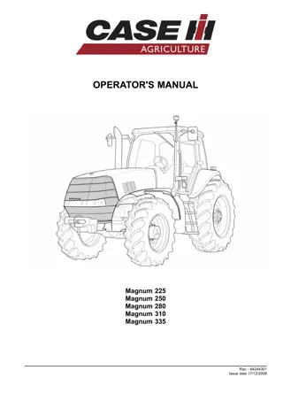
Case IH Magnum Series Tractor Operator’s Manual Instant Download (Publication No.84129624)
Please open the website below to get the complete manualnn//
Download Presentation

Please find below an Image/Link to download the presentation.
The content on the website is provided AS IS for your information and personal use only. It may not be sold, licensed, or shared on other websites without obtaining consent from the author. Download presentation by click this link. If you encounter any issues during the download, it is possible that the publisher has removed the file from their server.
E N D
Presentation Transcript
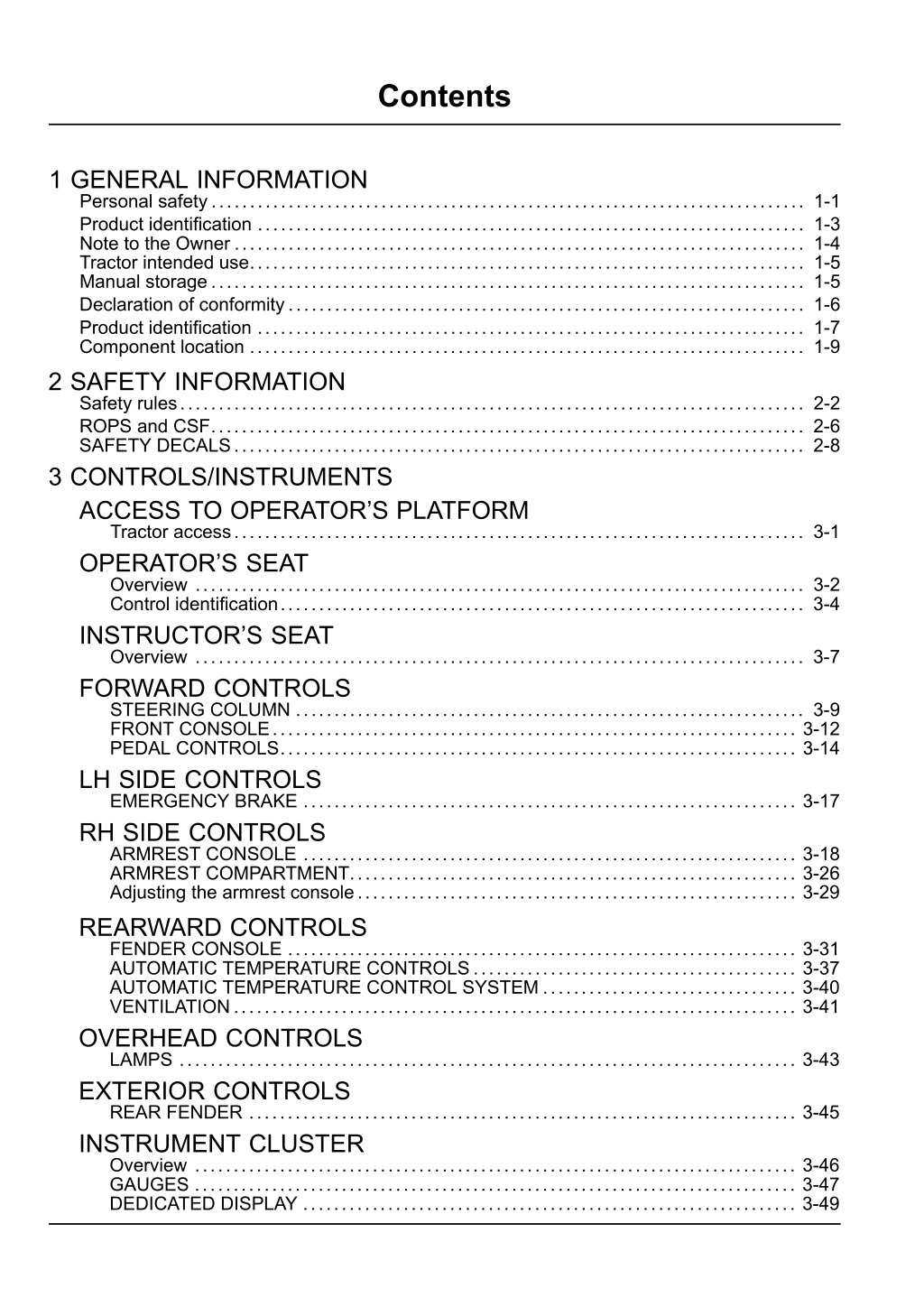
Contents 1 GENERAL INFORMATION Personal safety............................................................................. 1-1 Product identification ....................................................................... 1-3 Note to the Owner .......................................................................... 1-4 Tractor intended use........................................................................ 1-5 Manual storage............................................................................. 1-5 Declaration of conformity................................................................... 1-6 Product identification ....................................................................... 1-7 Component location ........................................................................ 1-9 2 SAFETY INFORMATION Safety rules................................................................................. 2-2 ROPS and CSF............................................................................. 2-6 SAFETY DECALS.......................................................................... 2-8 3 CONTROLS/INSTRUMENTS ACCESS TO OPERATOR S PLATFORM Tractor access.......................................................................... 3-1 OPERATOR S SEAT Overview ............................................................................... 3-2 Control identification.................................................................... 3-4 INSTRUCTOR S SEAT Overview ............................................................................... 3-7 FORWARD CONTROLS STEERING COLUMN .................................................................. 3-9 FRONT CONSOLE.................................................................... 3-12 PEDAL CONTROLS................................................................... 3-14 LH SIDE CONTROLS EMERGENCY BRAKE ................................................................ 3-17 RH SIDE CONTROLS ARMREST CONSOLE ................................................................ 3-18 ARMREST COMPARTMENT.......................................................... 3-26 Adjusting the armrest console......................................................... 3-29 REARWARD CONTROLS FENDER CONSOLE .................................................................. 3-31 AUTOMATIC TEMPERATURE CONTROLS.......................................... 3-37 AUTOMATIC TEMPERATURE CONTROL SYSTEM ................................. 3-40 VENTILATION......................................................................... 3-41 OVERHEAD CONTROLS LAMPS ................................................................................ 3-43 EXTERIOR CONTROLS REAR FENDER ....................................................................... 3-45 INSTRUMENT CLUSTER Overview .............................................................................. 3-46 GAUGES .............................................................................. 3-47 DEDICATED DISPLAY ................................................................ 3-49
KEYPAD............................................................................... 3-51 STATUS AND WARNING ICONS ..................................................... 3-54 PROGRAMMABLE DISPLAY ......................................................... 3-56 DISPLAY SETTINGS.................................................................. 3-76 OPERATOR PREFERENCES......................................................... 3-86 ICON LEGEND........................................................................ 3-96 4 OPERATING INSTRUCTIONS COMMISSIONING THE UNIT Before starting the engine .............................................................. 4-1 STARTING THE UNIT NORMAL ENGINE STARTING......................................................... 4-5 Cold temperature operation ............................................................ 4-8 STOPPING THE UNIT STOPPING THE ENGINE............................................................. 4-11 MOVING THE UNIT Powershift transmission ............................................................... 4-12 Transmission default gears............................................................ 4-13 Setting default gears .................................................................. 4-17 Best practices for prolonged transmission life......................................... 4-20 Transmission disengages; neutral icon flashes ....................................... 4-21 Automatic productivity management (APM)........................................... 4-22 Mechanical front drive (MFD).......................................................... 4-31 Differential lock system................................................................ 4-35 Suspended axle ....................................................................... 4-38 Ride control............................................................................ 4-46 Constant engine speed................................................................ 4-49 Electronic end of row system.......................................................... 4-51 5 TRANSPORT OPERATIONS ROAD TRANSPORT Tractor warning lamps.................................................................. 5-2 Tractor warning lamps.................................................................. 5-3 Safe transport speed ................................................................... 5-4 SHIPPING TRANSPORT Securing the tractor for shipping ....................................................... 5-5 RECOVERY TRANSPORT Safety rules............................................................................. 5-6 TOWING THE TRACTOR .............................................................. 5-7 6 WORKING OPERATIONS GENERAL INFORMATION Overview ............................................................................... 6-1 REAR PTO Safety rules......................................................................... 6-3 Connecting the PTO................................................................ 6-7 Interchangeable PTO shaft......................................................... 6-8 Reversible PTO shaft.............................................................. 6-14 PTO operation..................................................................... 6-16
PTO fender switch operation ...................................................... 6-20 Auto PTO operation ............................................................... 6-21 THREE POINT HITCH Identification ....................................................................... 6-26 Link adjustment.................................................................... 6-27 Hitch high clearance adjustment .................................................. 6-31 Hydraulic links ..................................................................... 6-34 Sway limiter adjustment ........................................................... 6-35 Lower link block adjustment ....................................................... 6-36 Mechanical float adjustment....................................................... 6-38 Hitch operation .................................................................... 6-39 Hitch remote switch operation..................................................... 6-45 Position control operation ......................................................... 6-46 Load control operation............................................................. 6-48 Slip control operation.............................................................. 6-50 Hitch set point ..................................................................... 6-53 FRONT HITCH Overview .......................................................................... 6-56 Hitch operation .................................................................... 6-58 DRAWBARS AND TOWING ATTACHMENTS Drawbar capacity/position ......................................................... 6-62 Adjusting the drawbar ............................................................. 6-64 TRAILER HITCHES Clevis and special drawbars....................................................... 6-66 Automatic trailer hitch ............................................................. 6-68 Auto pickup hitch operation........................................................ 6-71 Manual trailer hitch ................................................................ 6-73 AUXILIARY POWER CONNECTIONS Auxiliary power and lighting ....................................................... 6-76 Cab power connections ........................................................... 6-78 HYDRAULIC REMOTE CONTROL VALVES Valve couplers and connections................................................... 6-80 Motor return circuit ................................................................ 6-83 Power beyond circuit .............................................................. 6-84 Overview .......................................................................... 6-86 Operating the controls............................................................. 6-87 Changing the functional mode..................................................... 6-90 Remote hydraulic auto mode...................................................... 6-94 Auto depth control ................................................................. 6-97 BALLASTING THE TRACTOR Guidelines ........................................................................ 6-101 Tire load and inflation charts ..................................................... 6-105 Weights, cast metal and liquid.................................................... 6-106 Wheel slip and power hop performance ......................................... 6-113 MECHANICAL FRONT DRIVE (MFD) AXLES Tire combinations and tread positions............................................ 6-117 Steering and oscillation stops .................................................... 6-122
https://www.ebooklibonline.com Hello dear friend! Thank you very much for reading. Enter the link into your browser. The full manual is available for immediate download. https://www.ebooklibonline.com
REAR AXLE Rear wheel installation ........................................................... 6-125 Rear wheel tread settings ........................................................ 6-127 Rear wheel tread settings ........................................................ 6-142 7 MAINTENANCE GENERAL INFORMATION Safety rules............................................................................. 7-1 Opening the hood ...................................................................... 7-2 Battery access and service............................................................. 7-4 Tire and rim service..................................................................... 7-5 Tractor jacking points................................................................... 7-7 Capacities .............................................................................. 7-9 Consumables.......................................................................... 7-11 Electrical component location ......................................................... 7-15 Electrical system specification......................................................... 7-19 Maintenance chart notes .............................................................. 7-20 MAINTENANCE CHART Maintenance Chart .................................................................... 7-20 At warning message display Air filter service icon/message......................................................... 7-22 First 10 to 50 hours Differential and planetary oil........................................................... 7-23 Wheel bolt torque...................................................................... 7-24 Weight bolt torque ..................................................................... 7-25 Every 10 hours or daily Engine oil level ........................................................................ 7-26 Transmission oil level.................................................................. 7-27 Engine coolant level ................................................................... 7-28 Engine auxiliary fuel filter.............................................................. 7-29 Air tank - Drain fluid ................................................................... 7-30 Rear hitch and front axle .............................................................. 7-31 Every 50 hours Engine primary fuel filter............................................................... 7-32 Every 300 hours Battery water level (Note E) ........................................................... 7-33 Engine air intake hoses................................................................ 7-34 Engine coolant level - deaeration tank ................................................ 7-35 Engine oil and filter .................................................................... 7-36 Wheel bolt torque...................................................................... 7-38 Weight bolt torque ..................................................................... 7-39 Front axle (Note A) .................................................................... 7-40 Rear hitch (Note A).................................................................... 7-47 Fuel tank............................................................................... 7-49 Differential and planetary oil level (Note B)............................................ 7-50 Transmission oil pressure oil pressure ................................................ 7-52 Reversible 1000 RPM PTO shaft (Note D) ............................................ 7-54
Every 600 hours Engine coolant antifreeze protection .................................................. 7-55 Engine coolant filter ................................................................... 7-56 Engine coolant hoses and clamps..................................................... 7-57 Engine primary fuel filter............................................................... 7-58 Changeable PTO internal splines ..................................................... 7-60 Every 1200 hours or annually Differential and planetary oil........................................................... 7-61 Engine air filters ....................................................................... 7-65 Engine air precleaner.................................................................. 7-69 Every 1500 hours Transmission oil ....................................................................... 7-70 Transmission oil filter .................................................................. 7-72 Regulated transmission filter .......................................................... 7-73 Every 2100 hours Engine coolant......................................................................... 7-74 Fuel injector nozzles (Note C)......................................................... 7-77 Engine valve adjustment (Note C)..................................................... 7-77 Every 3000 hours Engine vibration damper (Note C)..................................................... 7-78 Emergency steering system........................................................... 7-79 As required Vehicle fire prevention................................................................. 7-81 Vehicle fire prevention................................................................. 7-82 Cab air filter............................................................................ 7-83 Engine primary air filter................................................................ 7-86 Grille screen and radiator area ........................................................ 7-89 Fuel tank vent filter .................................................................... 7-91 Transmission clutch and accumulator................................................. 7-91 Tire pressure .......................................................................... 7-91 Fan belt................................................................................ 7-92 Spark arresting muffler ................................................................ 7-93 Remote valve collection bottle......................................................... 7-94 Emergency brake lever................................................................ 7-95 Engine auxiliary fuel filter.............................................................. 7-96 Cab fabric and carpet.................................................................. 7-98 Seat belt ............................................................................... 7-99 STORAGE TRACTOR STORAGE............................................................ 7-100 REMOVAL FROM STORAGE.................................................... 7-100 ELECTRICAL SYSTEM Radio or audio system................................................................ 7-101 Battery removal and installation ...................................................... 7-102 Auxiliary battery connections......................................................... 7-104 Head light - Replace.................................................................. 7-105 Flood and work light .................................................................. 7-111
Fender tail light and warning light .................................................... 7-113 Roof front warning and work light .................................................... 7-115 Roof rear warning light ............................................................... 7-118 High intensity work light .............................................................. 7-120 Side turn indicator light ............................................................... 7-122 Rotating beacon light................................................................. 7-124 Number plate light .................................................................... 7-125 Interior light - Replace ................................................................ 7-126 8 TROUBLESHOOTING ALARM(S) Display warnings ................................................................... 8-1 9 SPECIFICATIONS ENGINE - General specification............................................................ 9-2 POWER TRAIN - General specification .................................................... 9-4 POWER TRAIN - General specification .................................................... 9-7 TRAVELLING - Speeds ................................................................... 9-10 Vehicle dimensions and shipping weight .................................................. 9-19 Maximum operating weight................................................................ 9-21 10 ACCESSORIES Front wheel fenders ....................................................................... 10-1 Farming system displays .................................................................. 10-7 Chemical tank mounting.................................................................. 10-10 Loader connection and operation ........................................................ 10-12 Trailer brake connections................................................................. 10-13 General accessories...................................................................... 10-18
GENERAL INFORMATION - 1 1 - GENERAL INFORMATION Personal safety THIS SAFETY ALERT SYMBOL INDICATES IMPORTANT SAFETY MESSAGES IN THIS MANUAL. WHEN YOU SEE THIS SYMBOL, CAREFULLY READ THE MESSAGE THAT FOLLOWS AND BE ALERT TO THE POSSIBILITY OF DEATH OR SERIOUS INJURY. Throughout this manual and on the machine s safety decals, you will find precautionary statements: DANGER< WARNING or CAUTION followed by special instructions or ISO two panel safety pictorial symbols. These precau- tions are intended for your personal safety. Failure to follow the DANGER, WARNING or CAUTION instructions may result in death or serious bodily injury. DANGER, WARNING or CAUTION are defined as follows: DANGER: Indicates an immediate hazardous situation that, if not avoided, will result in death or serious injury. The color associated with Danger is RED. WARNING: Indicates a potentially hazardous situation that, if not avoided, could result in death or serious injury. The color associated with Warning is ORANGE. CAUTION: Indicates a potentially hazardous situation that, if not avoided, could result in minor or moderate injury. It may also be used to alert against unsafe practices. The color associated with Caution is YELLOW. ISO two panel pictorial symbol decals are defined as follows: The first panel indicates the nature of the hazard. The second panel indicates the appropriate avoidance of the hazard Background color is YELLOW. Prohibition symbols such as and if used are RED. WARNING IMPROPER OPERATION OF THIS MACHINE CAN CAUSE DEATH OR SERIOUS INJURY. BEFORE USING THIS MACHINE, MAKE CERTAIN THAT EVERY OPERATOR: Is instructed in safe and proper use of the machine. Reads and understands the Manual(s) pertaining to the machine. Reads and understands ALL Safety Decals on the machine. Clears the area of other persons. Learns and practices safe use of machine controls in a safe, clear area before operating this machine on a job site. It is your responsibility to observe pertinent laws and regulations and follow CNH America LLC instructions on machine operation and maintenance. 1 - 1
GENERAL INFORMATION - 1 CNH America LLC technical manuals Manuals are available from your Dealer for the operation, service and repair of your machine. For prompt convenient service, contact your Dealer for assistance in obtaining the manuals for your machine. YouDealercanexpediteyourorderforOperatorsManuals, PartsCatalogs, RepairManualsandmaintenancerecords. Always give the Machine Name, Model and P.I.N. (product identification number) of your machine so your Dealer can provide the correct manuals for your machine. The company is continually striving to improve its products and therefore reserves the right to make improvements and changes when it becomes practical and possible to do so, without incurring any obligation to make changes or additions to the equipment sold previously. All data given in this manual is subject to production variations. IMPORTANT: OPERATING AND SERVICE MES- SAGES DISPLAYED ON THE ELECTRONIC OPERATING PANEL MAY VARY FROM WHAT IS SHOWN IN THE OP- ERATOR S MANUAL. SHOULD THIS OCCUR ADHERE TO THE LATEST INSTRUCTION ON THE ELECTRONIC OPERATING PANEL. Dimensions and weights are approximate only and the illustrations do not necessarily show the machine in standard condition. For exact information about any particular machine, please consult your dealer. 1 - 2
GENERAL INFORMATION - 1 Product identification 1 RCPH08CCH006FAB Dealer stamp CNH America LLC Racine, WI U.S.A. 1 - 3
GENERAL INFORMATION - 1 Note to the Owner This manual contains important information about the safe operation, adjustment and routine maintenance of your Magnum series tractor. The manual is divided into ten chapters as outlined in the table of contents. Refer to the index at the end of this manual for locating specific items about your tractor. This Operator s Manual is to be stored in the manual com- partment equipped on this machine. Make sure this man- ual is in good condition. Contact your dealer to obtain ad- ditional manuals. Contact your dealer for any further in- formation or assistance about your machine. Your dealer has approved service parts. Your dealer has technicians with special training that know the best methods of repair and maintenance for your tractor. Do NOT operate or permit anyone to operate or service this machine until you or the other persons have read this manual. Use only trained operators who have demon- strated the ability to operate and service this machine cor- rectly and safely. 1 - 4
GENERAL INFORMATION - 1 Tractor intended use This tractor is equipped solely for use in customary agri- cultural operation (intended use). and acquainted with the relevant safety rules (accident prevention). Use in any other way is considered as contrary to the intended use. The manufacture accepts no liability for any damage or injury resulting from this misuse and these risks must be born solely by the user. The accident prevention regulations, all other gener- ally recognized regulations on safety and occupational medicine and the road traffic regulations must be ob- served at all times. Compliance with and strict adherence to the conditions of operation, serviceandrepairasspecifiedbythemanufac- turer also constitute essential elements for the intended use. Any arbitrary modifications carried out on the tractor will relieve the manufacturer of all liability for any resulting damage or injury. This tractor must be operated, serviced and repaired only by persons familiar with all its particular characteristics Manual storage 1 RCPH08CCH002FAB Keep the Operator s Manual in the storage compartment provided on your tractor. The Operator s Manual must be available for use by all operators. The right hand and left hand side of the tractor used in this manual are the same as your right hand and left hand when sitting in the tractor seat looking forward. 1 - 5
GENERAL INFORMATION - 1 Declaration of conformity This tractor complies with the provisions of directive 89/336/EEC Electromagnetic Compatibility. EMC - supplementary information Safety information for the supplementary installation of electrical and electronic appliances and/or components. This tractor is equipped with electronic constituents and component parts whose function can be influenced by electromagnetic radiations of other appliances. Such influences can cause hazards for persons if the following safety information is not taken into account: 1. For supplementary installation of electrical and electronic appliances and/or constituents on the tractor with a connection to the onboard system, the user HAS to verify whether the installation causes disturbances to the elec- tronics on the tractor or other constituents. This particularly applies to: A. Powershift Control Button B. Instrument Cluster Also it has to be taken into account that the supplementary installed electrical and electronic components comply with the EMC Directive 89/336/EEC in the respective current version and that they are CE marked. For the supplementary installation of mobile communication systems (i.e. radio communication, mobile telephone) the following additional requirements have to be fulfilled: 2. A. Only devices with an approval complying with the valid national regulations must be installed. B. The devices must be firmly installed. C. The operation of portable or mobile devices within the cab of the tractor is ONLY permitted if the device has a fixed outside antenna. D. The transmitting part shall be installed separately to the tractor electronics. E. Installation of the antenna must be carried out by a professional and the antenna must have a good ground connection between the antenna and the tractor ground. For the correct size cabling, installation and the maximum permissible current supply, the installation instructions of the tractor manufacturer have to be considered additionally. 1 - 6
GENERAL INFORMATION - 1 Product identification Tractor model and product identification number Model : PIN NOTE: Located on right hand front casting. 1 RCPH08CCH486AAB Roll over protection system (ROPS) serial number NOTE: Located on the right hand cab floor. 2 RCPH08CCH482AAB Engine serial number NOTE: Located on the front left hand side of the engine.. 3 RCPH08CCH479AAB 1 - 7
GENERAL INFORMATION - 1 Transmission serial number NOTE: Located on the right hand side of the transmission (speed housing) behind the fuel tank and to the left of the ground stud. 4 RCPH08CCH483AAB Axle serial number MFD axle: Located on the rear right hand side of the axle housing (1) (shown). Saddle suspended axle: Located on the rear right hand side of the axle housing (not shown). Scissors suspended axle: Located on the front right hand side of the axle housing (not shown). 5 RCPH08CCH484AAB 1 - 8
GENERAL INFORMATION - 1 Component location 1 RCPH08CCH006FAB 6. Hood latch 7. Front weight bracket 8. Front clevis 9. Exhaust stack 10. Extendible mirror 11. Beacon 12. Work lamps 13. Amber warning lamps 14. Road/work lamps 15. HID lamp 1. ROPS cab 2. Hand rail 3. Steps 4. Fuel tank 5. Hood 1 - 9
GENERAL INFORMATION - 1 2 RCPH08CCH007FAB 1. Drawbar 2. PTO with shield 3. Red reflector 4. Rear hitch 5. Exterior hitch control 6. Speed symbol 7. Brake/tail lamp 8. Amber warning lamp 9. Work lamp 1 - 10
SAFETY INFORMATION - 2 2 - SAFETY INFORMATION 2 - 1
SAFETY INFORMATION - 2 Safety rules Understand that your safety and the safety of other persons is measured by how you service and operate this ma- chine. Know the positions and operation of all controls before you try to operate. MAKE SURE YOU CHECK ALL CONTROLS IN A SAFE AREA BEFORE STARTING YOUR WORK. READ THIS MANUAL COMPLETELY and make sure you understand the controls. All equipment has limits. Make sure you understand the speed, brakes, steering stability and load characteristics of this machine before you start to operate. The safety information given in this manual does not replace safety codes, insurance needs, federal, state and local laws. Make sure your machine has the correct equipment needed by the local laws and regulations. CNH America LLC is continuing to work for your safety by making tractors with better protection and by providing these rules for safe operation. General safety and accident prevention regulations In addition to the instructions contained in this opera- tor s manual, also observe the general safety and ac- cident prevention regulations. Never run the engine in a closed building. Proper ventilation is required. Clothing worn by the operator must be close-fitting. Avoid wearing loose jackets, shirts or ties. Always comply with local traffic regulations when driv- ing on public roads. Handle fuel with care as it is highly flammable. Never refuel the machine in the vicinity of naked flames or sparks. Do not smoke during refuelling. Before starting work, familiarize yourself with all the controls and instruments and their functions. During work is too late. Always stop the engine and remove the main switch key before refuelling. Fill fuel tank outdoors. Clean up any spilled fuel immediately. Start the engine only from the operator s seat. Never attempt to start engine by shorting across the starting motor terminals as the machine may immedi- ately start to move. Prevent fires by keeping the machine clean. Take care when handling brake fluid and battery acid (toxic and corrosive). Before moving away, always check the immediate vicinity of the machine (e.g. for children). Ensure adequate visibility. Operation Always adapt your ground speed to the ground con- ditions. Avoid making sharp turns when driving up or down slopes or when driving across the slope. Do not attempt to turn the machine with the differential lock engaged. When driving down slopes, never depress the clutch and change gear. Therefore ensure adequate steering and braking power. Observe maximum permissible axle loads and total weights. When making turns with towed or mounted imple- ments, always take into consideration the width and inertia of the implement. Attach trailers and/or implements correctly. The oper- ating, steering and braking behavior will be affected by attaching implements, trailers and ballast weights. Leaving the tractor When leaving the tractor, ensure that it will not roll away (apply park brake, wheel wedges) stop the en- gine and remove key. Never leave the tractor unattended as long as the en- gine is still running. Never leave the operator s platform/cab when driving. Remove the main switch key and lock the operator s cab. Lower implement or equipment to the ground before leaving the tractor. 2 - 2
Suggest: If the above button click is invalid. Please download this document first, and then click the above link to download the complete manual. Thank you so much for reading
SAFETY INFORMATION - 2 Implements Attach implements and trailers to the tractor only using the prescribed drawbars or hitches. Properly connect the auxiliary brake system. Properly connect the auxiliary lighting harness. Use only recommended hardware for hitch connec- tions. Verify the integrity of the connection. Do not exceed implement transport speed or the speed rating on the implement tires. implements Operator s Manual for specifications. Review the Prevent trailer and implement from moving when de- tached from the tractor. Operate tractor only when all guards are fitted and in their correct position. PTO operation Always shut off engine before connecting or discon- necting drive shaft. High-inertia implements do not become stationary im- mediately when PTO is disengaged. Allow sufficient time for implement to coast down to a halt before cleaning or adjusting. When operating the PTO, no-one is allowed to remain in the vicinity of the rotating PTO stub shaft or drive shaft. As soon as drive shaft has been removed, install guard over PTO stub shaft. Guards for drive shaft and PTO stub shaft must be fitted. Service Donotservicethetractorwiththeenginerunning. Fol- low the instructions in this manual or see your dealer. devices that are necessary for the particular proce- dure. Some personal safety devices that may be necessary are protective shoes, face and/or eye protection, hard hat, heavy gloves, filter mask and hearing protection. Escaping fluid (fuel or hydraulic oil) under high pres- sure can penetrate the skin and cause serious injury. If any fluid is injected into the skin, consult a doctor im- mediately as otherwise serious infections may result. Do Not wear jewelry or loose fitting clothing that may get caught in moving parts. Always wear close fitting clothing. Keep hands, feet, clothing and hair away from moving parts. Dispose of oil, fuel and filters in accordance with local regulations. Do not drain the oil on the ground or into a drain. Be responsible for the environment. Never attempt to clear obstructions or objects from the machine while the engine is running. Do not attempt to mount a tire unless you have the proper equipment and experience to perform the job safely. Always stop the engine and remove the key from the key switch when leaving the operators seat or the ma- chine. Do not attempt to lift the tractor to remove a wheel without using the recommended jacking procedure. When servicing the machine, always have the ma- chine on a firm level surface. Retighten wheel nuts after the specified hours in this manual. Ifshieldsorguardsareremovedoropenedforservice, always replace them before operating the machine. Never operate machine with missing or open shields or guards. Always disconnect the battery ground strap (S) before carrying out any electrical repairs on the machine. Use original manufacturers parts. Spare parts/service parts must comply with the manufacturers technical specifications. Keep the area used for servicing the machine clean and dry. Wet or oily floors are slippery. Wet spots can bedangerouswhenworkingwithelectricalequipment. Be sure all electrical outlets and tools are properly grounded. Always keep safety and informational decals clean and visible. Replace decals that are damaged, lost, painted over or can not be read. When assembling, operating or servicing the ma- chine, wear protective clothing and personal safety 2 - 3
https://www.ebooklibonline.com Hello dear friend! Thank you very much for reading. Enter the link into your browser. The full manual is available for immediate download. https://www.ebooklibonline.com

