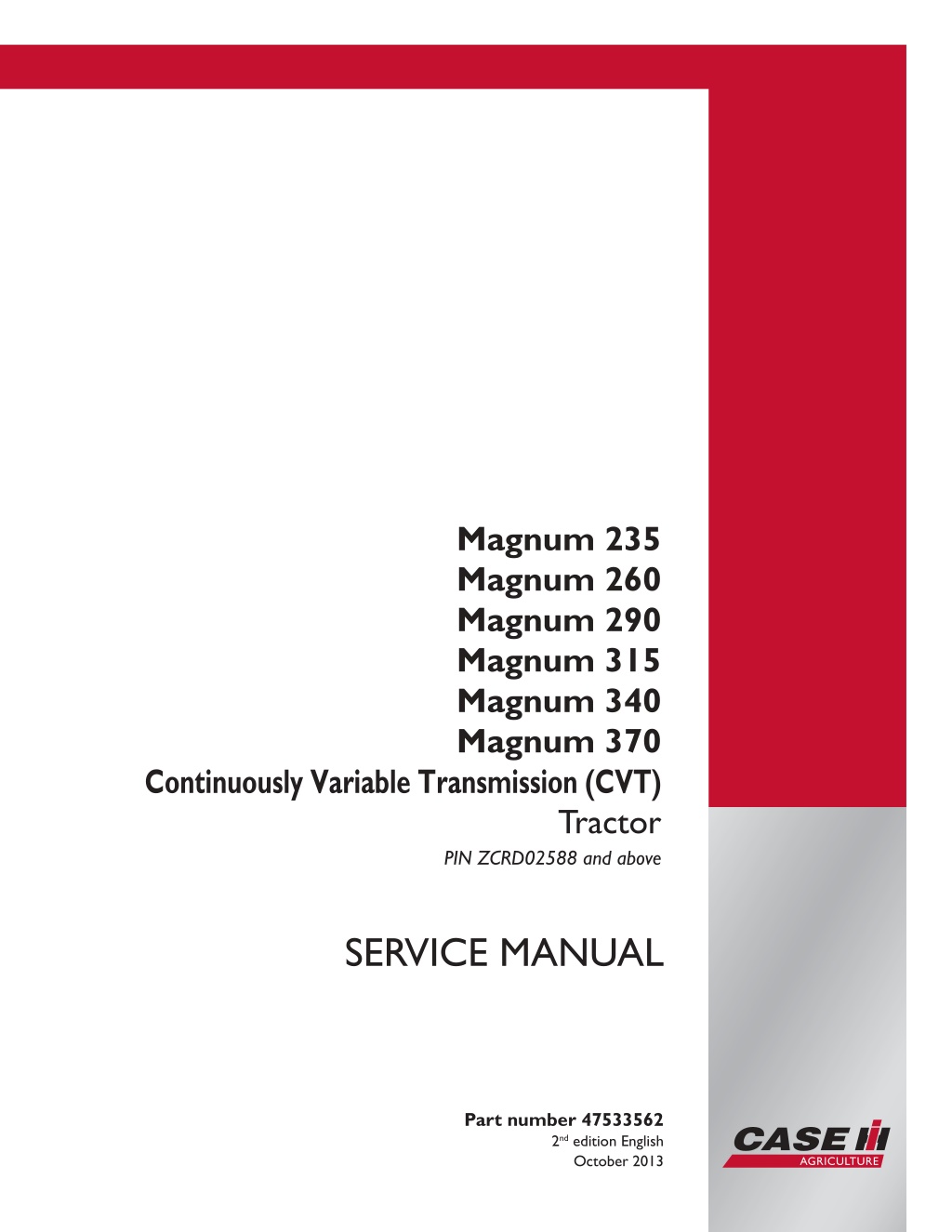
CASE IH Magnum 235 260 290 315 340 370 Continuously Variable Transmission (CVT) Tractor Service Repair Manual Instant Download (PIN ZCRD02588 and above)
Please open the website below to get the complete manualnn//
Download Presentation

Please find below an Image/Link to download the presentation.
The content on the website is provided AS IS for your information and personal use only. It may not be sold, licensed, or shared on other websites without obtaining consent from the author. Download presentation by click this link. If you encounter any issues during the download, it is possible that the publisher has removed the file from their server.
E N D
Presentation Transcript
Magnum 235 Magnum 260 Magnum 290 Magnum 315 Magnum 340 Magnum 370 Continuously Variable Transmission (CVT) Tractor PIN ZCRD02588 and above SERVICE MANUAL Printed in U.S.A. Part number 47533562 2nd edition English Copyright 2013 CNH America LLC. All Rights Reserved. Case IH is a registered trademark of CNH America LLC. Racine Wisconsin 53404 U.S.A. October 2013
Contents INTRODUCTION Engine....................................................................................... 10 [10.001] Engine and crankcase ............................................................. 10.1 [10.101] Cylinder heads ..................................................................... 10.2 [10.114] Pump drives ........................................................................ 10.3 [10.202] Air cleaners and lines .............................................................. 10.4 [10.216] Fuel tanks .......................................................................... 10.5 [10.310] Aftercooler.......................................................................... 10.6 [10.400] Engine cooling system ............................................................. 10.7 [10.414] Fan and drive ...................................................................... 10.8 [10.500] Selective Catalytic Reduction (SCR) exhaust treatment........................... 10.9 Power coupling........................................................................... 19 [19.100] Drive shaft.......................................................................... 19.1 Transmission.............................................................................. 21 [21.504] Continuously Variable Transmission (CVT) ........................................ 21.1 [21.505] Continuously Variable Transmission (CVT) external controls...................... 21.2 [21.507] Continuously Variable Transmission (CVT) internal components.................. 21.3 [21.506] Continuously Variable Transmission (CVT) lubrication system .................... 21.4 Four-Wheel Drive (4WD) system .................................................. 23 [23.202] Electro-hydraulic control ........................................................... 23.1 [23.314] Drive shaft.......................................................................... 23.2 Front axle system ....................................................................... 25 [25.100] Powered front axle ................................................................. 25.1 [25.102] Front bevel gear set and differential ............................................... 25.2 [25.108] Final drive hub, steering knuckles, and shafts ..................................... 25.3 [25.122] Axle suspension control............................................................ 25.4 47533562 02/10/2013
Rear axle system........................................................................ 27 [27.100] Powered rear axle.................................................................. 27.1 [27.106] Rear bevel gear set and differential................................................ 27.2 [27.120] Planetary and final drives .......................................................... 27.3 Power Take-Off (PTO)................................................................. 31 [31.104] Rear electro-hydraulic control...................................................... 31.1 [31.110] One-speed rear Power Take-Off (PTO) ............................................ 31.2 [31.114] Two-speed rear Power Take-Off (PTO) ............................................ 31.3 [31.146] Front Power Take-Off (PTO) ....................................................... 31.4 Brakes and controls .................................................................... 33 [33.110] Parking brake or parking lock ...................................................... 33.1 [33.202] Hydraulic service brakes ........................................................... 33.2 [33.220] Trailer brake hydraulic control...................................................... 33.3 [33.224] Trailer brake pneumatic control .................................................... 33.4 Hydraulic systems....................................................................... 35 [35.000] Hydraulic systems.................................................................. 35.1 [35.102] Pump control valves................................................................ 35.2 [35.106] Variable displacement pump ....................................................... 35.3 [35.114] Three-point hitch control valve ..................................................... 35.4 [35.124] Three-point hitch hydraulic adjustment ............................................ 35.5 [35.204] Remote control valves ............................................................. 35.6 [35.300] Reservoir, cooler, and filters........................................................ 35.7 [35.304] Combination pump units ........................................................... 35.8 Pneumatic system ...................................................................... 36 [36.100] Pneumatic system.................................................................. 36.1 Hitches, drawbars, and implement couplings.................................. 37 [37.110] Rear three-point hitch .............................................................. 37.1 [37.162] Front hitch.......................................................................... 37.2 47533562 02/10/2013
https://www.ebooklibonline.com Hello dear friend! Thank you very much for reading. Enter the link into your browser. The full manual is available for immediate download. https://www.ebooklibonline.com
Steering..................................................................................... 41 [41.101] Steering control .................................................................... 41.1 [41.200] Hydraulic control components...................................................... 41.2 [41.206] Pump............................................................................... 41.3 Cab climate control..................................................................... 50 [50.100] Heating............................................................................. 50.1 [50.200] Air conditioning..................................................................... 50.2 [50.300] Cab pressurizing system........................................................... 50.3 Electrical systems....................................................................... 55 [55.012] Engine cooling system ............................................................. 55.1 [55.015] Engine control system.............................................................. 55.2 [55.024] Transmission control system....................................................... 55.3 [55.045] Front axle control system .......................................................... 55.4 [55.046] Rear axle control system........................................................... 55.5 [55.050] Heating, Ventilation, and Air-Conditioning (HVAC) control system................. 55.6 [55.051] Cab Heating, Ventilation, and Air-Conditioning (HVAC) controls................... 55.7 [55.100] Harnesses and connectors......................................................... 55.8 [55.130] Rear three-point hitch electronic control system ................................... 55.9 [55.201] Engine starting system........................................................... 55.10 [55.301] Alternator......................................................................... 55.11 [55.302] Battery............................................................................ 55.12 [55.404] External lighting .................................................................. 55.13 [55.405] External lighting switches and relays ............................................ 55.14 [55.408] Warning indicators, alarms, and instruments .................................... 55.15 [55.512] Cab controls...................................................................... 55.16 [55.514] Cab lighting ...................................................................... 55.17 [55.518] Wiper and washer system........................................................ 55.18 47533562 02/10/2013
[55.640] Electronic modules............................................................... 55.19 [55.988] Selective Catalytic Reduction (SCR) electrical system .......................... 55.20 [55.DTC] FAULT CODES.................................................................. 55.21 Platform, cab, bodywork, and decals............................................. 90 [90.100] Engine hood and panels ........................................................... 90.1 [90.102] Engine shields, hood latches, and trims ........................................... 90.2 [90.118] Protections and footboards......................................................... 90.3 [90.124] Pneumatically-adjusted operator seat.............................................. 90.4 [90.150] Cab................................................................................. 90.5 [90.151] Cab interior......................................................................... 90.6 [90.160] Cab interior trim and panels........................................................ 90.7 47533562 02/10/2013
INTRODUCTION 47533562 02/10/2013 1
INTRODUCTION Foreword - Important notice regarding equipment servicing Magnum 235 [ZCRD02588 - ] NA, Magnum 260 [ZCRD02588 - ] NA, Magnum 290 [ZCRD02588 - ] NA, Magnum 315 [ZCRD02588 - ] NA, Magnum 340 [ZCRD02588 - ] NA, Magnum 370 [ZCRD02588 - ] NA All repair and maintenance work listed in this manual must be carried out only by qualified dealership personnel, strictly complying with the instructions given, and using, whenever possible, the special tools. Anyone who performs repair and maintenance operations without complying with the procedures provided herein shall be responsible for any subsequent damages. The manufacturer and all the organizations of its distribution chain, including - without limitation - national, regional, or local dealers, reject any responsibility for damages caused by parts and/or components not approved by the manu- facturer, including those used for the servicing or repair of the product manufactured or marketed by the manufacturer. In any case, no warranty is given or attributed on the product manufactured or marketed by the manufacturer in case of damages caused by parts and/or components not approved by the manufacturer. The information in this manual is up-to-date at the date of the publication. It is the policy of the manufacturer for continuous improvement. Some information could not be updated due to modifications of a technical or commercial type, or changes to the laws and regulations of different countries. In case of questions, refer to your CASE IH Sales and Service Networks. 47533562 02/10/2013 3
INTRODUCTION Safety rules Magnum 235 NA, Magnum 260 NA, Magnum 290 NA, Magnum 315 NA, Magnum 340 NA, Magnum 370 Personal safety This is the safety alert symbol. It is used to alert you to potential personal injury hazards. Obey all safety messages that follow this symbol to avoid possible death or injury. Throughout this manual and on machine decals, you will find the signal words DANGER, WARNING, and CAUTION followed by special instructions. These precautions are intended for the personal safety of you and those working with you. Read and understand all the safety messages in this manual before you operate or service the machine. DANGER indicates a hazardous situation which, if not avoided, will result in death or serious injury. The color associated with DANGER is RED. WARNING indicates a hazardous situation which, if not avoided, could result in death or serious injury. The color associated with WARNING is ORANGE. CAUTION, used with the safety alert symbol, indicates a hazardous situation which, if not avoided, could result in minor or moderate injury. The color associated with CAUTION is YELLOW. FAILURE TO FOLLOW DANGER, WARNING, AND CAUTION MESSAGES COULD RESULT IN DEATH OR SERIOUS INJURY. Machine safety NOTICE: Notice indicates a situation which, if not avoided, could result in machine or property damage. The color associated with Notice is BLUE. Throughout this manual you will find the signal word Notice followed by special instructions to prevent machine or property damage. The word Notice is used to address practices not related to personal safety. Information NOTE: Note indicates additional information which clarifies steps, procedures, or other information in this manual. Throughout this manual you will find the word Note followed by additional information about a step, procedure, or other information in the manual. The word Note is not intended to address personal safety or property damage. 47533562 02/10/2013 4
INTRODUCTION Safety rules - General maintenance safety Magnum 235 [ZCRD02588 - ] NA, Magnum 260 [ZCRD02588 - ] NA, Magnum 290 [ZCRD02588 - ] NA, Magnum 315 [ZCRD02588 - ] NA, Magnum 340 [ZCRD02588 - ] NA, Magnum 370 [ZCRD02588 - ] NA General maintenance safety Keep the area used for servicing the machine clean and dry. Clean up spilled fluids. Service the machine on a firm, level surface. Install guards and shields after you service the machine. Close all access doors and install all panels after servicing the machine. Do not attempt to clean, lubricate, clear obstructions, or make adjustments to the machine while it is in motion or while the engine is running. Always make sure that working area is clear of tools, parts, other persons and pets before you start operating the machine. Unsupported hydraulic cylinders can lose pressure and drop the equipment, causing a crushing hazard. Do not leave equipment in a raised position while parked or during service, unless the equipment is securely supported. Jack or lift the machine only at jack or lift points indicated in this manual. Incorrect towing procedures can cause accidents. When you tow a disabled machine follow the procedure in this manual. Use only rigid tow bars. Stop the engine, remove the key, and relieve pressure before you connect or disconnect fluid lines. Stop the engine and remove the key before you connect or disconnect electrical connections. Scalding can result from incorrect removal of coolant caps. Cooling systems operate under pressure. Hot coolant can spray out if you remove a cap while the system is hot. Allow the system to cool before you remove the cap. When you remove the cap, turn it slowly to allow pressure to escape before you completely remove the cap. Replace damaged or worn tubes, hoses, electrical wiring, etc. The engine, transmission, exhaust components, and hydraulic lines may become hot during operation. Take care when you service such components. Allow surfaces to cool before you handle or disconnect hot components. Wear protective equipment when appropriate. When welding, follow the instructions in the manual. Always disconnect the battery before you weld on the machine. Always wash your hands after you handle battery components. 47533562 02/10/2013 5
SERVICE MANUAL Engine Magnum 235 [ZCRD02588 - ] , Magnum 260 [ZCRD02588 - ] , Magnum 290 [ZCRD02588 - ] , Magnum 315 [ZCRD02588 - ] , Magnum 340 [ZCRD02588 - ] , Magnum 370 [ZCRD02588 - ] 47533562 02/10/2013 10
Engine - Engine and crankcase Engine - Remove Magnum 235, Magnum 260, Magnum 290, Magnum 315, Magnum 340, Magnum 370 [ZCRD02588 - ] Prior operation: Battery - Disconnect (55.302) Prior operation: Side shield - Remove (90.102) Prior operation: Hood - Remove (90.100) Prior operation: Engine cooling system - Emptying (10.400) Prior operation: Air conditioning - Recover (50.200) NOTE: During the disassembly of components with O-ring seals, the seals should be discarded and new seal installed during assembly. NOTE: Cap all fittings and plug all lines/hoses as they are disconnected. 1. Disconnect the hydraulic cooling line connection on the right side (from oil cooler). NOTE: Be prepared to collect some hydraulic oil by placing a pan under the fitting. 1 RCPH10CCH771AAB 2. Disconnect the hydraulic line (1) on the left side (to oil cooler). Disconnect the engine cooling fan drive harness connector (3) 3. Disconnect the air conditioning low pressure hose to line fitting (return from condenser) (2). 4. Remove the bolt securing the harness P-clamp (4). 2 RCPH10CCH772AAB 5. Disconnect the air conditioning high pressure hose to tube fitting (1). 6. Disengage the hose clamps (2), and disconnect the cooler hoses (3) (4). 3 RCPH10CCH773AAB 47533562 02/10/2013 10.1 [10.001] / 3
Engine - Engine and crankcase 7. Disengage the hose clamps (1) and disconnect the air vent hose (2) and the hose (3) from the deaeration tank to the recovery bottle. 4 RCPH10CCH774AAB 8. Loosen the turbocharger clamp (1). 9. Loosen the air cooler inlet hose clamp (2). 10. Remove the pipe (3) and set aside. 11. Repeat for the right side air to air tube from the cooler to the intake manifold (not shown). 5 RCPH10CCH775AAB 12. Remove and discard the O-ring seal from the elbow. 6 RCPH10CCH778AAB 13. Remove and discard the O-ring seal from the elbow. 7 RCPH10CCH777AAB 47533562 02/10/2013 10.1 [10.001] / 4
Engine - Engine and crankcase 14. Loosen the hose clamp (1) at the engine coolant outlet and disconnect the hose from the thermostat housing. 8 RCPH10CCH776AAB 15. Loosen the hose clamp and disconnect the coolant line into the engine hose. 9 RCPH10CCH580AAB 16. Remove the nuts (1) and disengage the engine heater grid cables (2) (3) to the fuse block. 17. Disconnect the harness connector (4) for the 12 V auxiliary power connection . 10 RCPH10CCH779AAB 18. Disconnect the ECM (engine control module) connec- tor (1) by moving the locking handle (2) from the right (locked position) to the left (unlocked position). 11 RCPH10CCH780AAB 47533562 02/10/2013 10.1 [10.001] / 5
Engine - Engine and crankcase 19. Disconnect the tractor to engine harness connectors (1). 12 RCPH10CCH781AAB 20. Disconnect the harness connectors to the alternator (1) and the A/C compressor clutch (2). 21. Remove the upper left A/C compressor bolt and re- move the ground wire (3). 13 RCPH10CCH782AAB 22. Disconnect the harness connectors to the A/C high pressure switch (1) and the engine cooling fan drive (2). 14 RCPH10CCH783AAB 23. Disconnect the harness connector (1) to the grid heater controller. 15 RCPH10CCH784AAB 47533562 02/10/2013 10.1 [10.001] / 6
Engine - Engine and crankcase 24. Remove the nut (1) and the clamp bolts (2). Disen- gage the power cable (3). 16 RCPH10CCH785AAB 25. Loosen the nut (1) and disconnect the fuel supply line to the EMC cooler 17 RCPH10CCH787AAB 26. Disengage the clamp (1) and disconnect the fuel re- turn hose (2) from the pipe. 18 RCPH10CCH786AAB 27. Remove the nut (1) and disengage the alternator out- put cable (2). 19 RCPH10CCH788AAB 47533562 02/10/2013 10.1 [10.001] / 7
Engine - Engine and crankcase 28. Loosen the nuts (1) and disconnect the compressor inlet (2) and outlet (3) tubes. 20 RCPH10CCH789AAB 29. Disconnect the harness connector to the SCR heater control valve solenoid (1). 30. Raise the locking wire (2) and disconnect the heater supply connector (3) from the valve. 31. Repeat for the outlet hose connection (located on the right side of the valve). 21 RCPH10CCH790AAB 32. Disconnect the main engine to chassis harness con- nector. 22 RCPH10CCH791AAB 33. Disconnect the auxiliary engine to chassis harness connectors (1). 23 RCPH10CCH792AAB 47533562 02/10/2013 10.1 [10.001] / 8
Engine - Engine and crankcase 34. Remove the holding nut (1) and disengage the ground wire (2). 24 RCPH10CCH793AAB 35. Loosen the fitting and disconnect the hydraulic oil line (1) (right side of engine). 25 RCPH10CCH798AAB 36. Disconnect the water in fuel sensor connector (1) from the primary fuel filter. 26 RCPH10CCH794AAB 37. Loosen the nuts (1) and disconnect the A/C lines lo- cated between the hood support and the cab. 27 RCPH10CCH799AAB 47533562 02/10/2013 10.1 [10.001] / 9
Engine - Engine and crankcase 38. Remove the jump start stud. 28 RCPH10CCH796AAB 39. Remove the nut (1) and disengage the cables from the starter. 29 RCPH10CCH797AAB 40. Remove the plug (1), remove the attaching screw (2) and remove the starter solenoid wire (3). 30 RCPH10CCH818AAB 41. Loosenthehoseclamp(1)anddisconnectthefillhose elbow (2). 31 RCPH10CCH795AAB 47533562 02/10/2013 10.1 [10.001] / 10
Engine - Engine and crankcase 42. Remove the six socket head bolts (1) and three back- ing plates (2) securing the drive shaft assembly to the engine drive pulley. Disengage the drive from the pul- ley. 32 RCPH10CCH562AAB 43. Remove the nuts and washers (1) from the cooling assembly support bracket on the left and right sides. 33 RCPH10CCH572AAB 44. Properly support the bracket, and remove the four bolts (1) securing the bracket to the hood support. Re- move the assembly and set aside. 34 RCPH10CCH037BAB 45. Loosen the clamp (1) and disconnect the coolant fill line. 46. Loosen the nuts (2) and (3) and disconnect the cab heater supply and return lines. 47. Disengage the clamp (4) and remove the air bleed hose. 48. Remove the three bolts (5) securing the front support bracket. 35 RCPH10CCH038BAB 47533562 02/10/2013 10.1 [10.001] / 11
Engine - Engine and crankcase 49. Remove the two bolts (1) securing the rear support bracket. 36 RCPH10CCH800AAB 50. Disconnect the harness connector (1) to the dosing valve. 37 RCPH10CCH801AAB 51. Disconnect the DEF supply and return hoses (1). NOTE: Squeeze the locking tabs (2) together and pull straight upward on the elbow. 38 RCPH10CCH359AAB 52. Remove the clamp (1) at the turbocharger. Repeat for clamp at the other end of the pipe (2). Remove the pipe and set aside. 39 RCPH10CCH806AAB 47533562 02/10/2013 10.1 [10.001] / 12
Engine - Engine and crankcase 53. Remove the clamp (1) at the SCR muffler. Remove the attaching bolt (2) securing the support bracket. Remove the pipe and set aside. 40 RCPH10CCH803AAB 54. Disengage the engine blow-by hose clamp (1) at the intake pipe. Disconnect from the intake pipe. 41 RCPH10CCH805AAB 55. Disengage the engine blow-by hose clamp (1) at the engine. Remove the pipe and set aside. 42 RCPH10CCH807AAB 56. Loosen the clamp (1) securing the intake pipe elbow to the turbocharger. Disconnect from the turbo. 43 RCPH10CCH809AAB 47533562 02/10/2013 10.1 [10.001] / 13
Engine - Engine and crankcase 57. Remove the two bolts (1) securing the support clamp to the intake pipe. 44 RCPH10CCH808AAB 58. Remove the bolt (1) securing the intake support clamp to the bracket. Loosen the clamp (2). Remove the upper intake pipe and set aside. 45 RCPH10CCH804AAB 59. Remove the bolt (1) securing the intake pipe support clamp. 46 RCPH10CCH811AAB 60. Loosen the clamp (1) and remove the intake elbow and pipe assembly (2) from the air cleaner outlet. 47 RCPH10CCH810AAB 47533562 02/10/2013 10.1 [10.001] / 14
Engine - Engine and crankcase 61. Remove the two fasteners (1) securing the two halves of the engine drive shaft cover. 48 RCPH10CCH812AAB 62. Remove the cover bolts (1). Remove the covers and set aside. 49 RCPH10CCH813AAB 63. Mark the drive shaft (1). Remove the four bolts (2) and disengage the drive shaft from the flywheel. 50 RCPH10CCH817AAB 64. Remove the two bolts (1) securing the front engine mount bracket. Remove the bracket (2) and set aside. 51 RCPH10CCH814AAB 47533562 02/10/2013 10.1 [10.001] / 15
Engine - Engine and crankcase 65. Remove the two bolts (1) securing the right rear en- gine mount plate. Remove the plate (2) and set aside. 52 RCPH10CCH815AAB 66. Remove the two bolts (1) securing the left rear en- gine mount plate. Remove the plate (2) along with the ground strap (3) and set aside. 53 RCPH10CCH816AAB 67. Remove the hose clamp (located at the rear of the en- gine) securing the hydraulic hoses. Move the assem- bly (from the left side of the engine) off to the side. 54 RCPH10CCH829AAB WARNING Heavy objects! Lift and handle all heavy components us- ing lifting equipment with adequate capac- ity. Always support units or parts with suit- able slings or hooks. Make sure the work area is clear of all bystanders. Failure to comply could result in death or serious injury. 68. W0398A Use an appropriate device to support the engine, and carefully remove the engine making sure all hoses, lines and harnesses are disconnected. 55 RCPH10CCH832AAB 47533562 02/10/2013 10.1 [10.001] / 16
Engine - Engine and crankcase 69. Remove the rear engine mount. and/or damage. Replace as required. Repeat for the left side. Inspect for wear 56 RCPH07CCH166AAB 70. Remove the bolt and nut (1) securing the front mount enginemount(2). Inspectmountforwearand/ordam- age. Replace as required. 57 RCPH10CCH833AAB Next operation: Engine - Install (10.001) 47533562 02/10/2013 10.1 [10.001] / 17
Engine - Engine and crankcase Engine - Install Magnum 235, Magnum 260, Magnum 290, Magnum 315, Magnum 340, Magnum 370 [ZCRD02588 - ] Prior operation: Engine - Remove (10.001) NOTE: During the assembly of components with O-ring seals, new seals should be lubricated and installed. 1. Install the rear engine mounts. 1 RCPH07CCH166AAB 2. If front engine mount brackets (4) were removed, re- install and secure with the four(4) bolts (1) previously removed. 3. Torque the bolts to 110 - 113 N m (81 - 83 lb ft). 4. Position the mount (3), install the bolt and torque the nut (2) to 160 - 220 N m (118 - 162 lb ft). 2 RCPH10CCH833AAB WARNING Heavy objects! Lift and handle all heavy components us- ing lifting equipment with adequate capac- ity. Always support units or parts with suit- able slings or hooks. Make sure the work area is clear of all bystanders. Failure to comply could result in death or serious injury. 5. W0398A Support the engine with proper lifting equipment and lower the engine into position in the front frame. 3 RCPH10CCH832AAB 47533562 02/10/2013 10.1 [10.001] / 18
Engine - Engine and crankcase 6. Install the front mount bracket (1). 7. Install the bolts (2) removed previously, and torque to 31 - 36 N m (23 - 27 lb ft). 4 RCPH10CCH814AAB 8. Install the plate (1) for the right rear mount. 9. Install the bolts (2) removed previously, and torque to 125 - 150 N m (92 - 111 lb ft). 5 RCPH10CCH815AAB 10. Install the plate (1) for the left rear mount. 11. Install the bolts (2) removed previously, along with the grounding strap (3), and torque to 125 - 150 N m (92 - 111 lb ft). 6 RCPH10CCH816AAB 12. Align the marks (1) and attach the drive shaft. 13. Install the four bolts (2) removed previously, and torque to 101 - 113 N m (74 - 83 lb ft). 7 RCPH10CCH817AAB 47533562 02/10/2013 10.1 [10.001] / 19
Engine - Engine and crankcase 14. Position the two sections of drive shaft cover (1) and secure with the bolts (2) removed previously. 8 RCPH10CCH813AAB 15. Install two new plastic fasteners (1) through the cover halves. 9 RCPH10CCH812AAB 16. At the left side of the engine, install the rear tube sup- port bracket (1). Using the bolts (2) removed earlier, secure bracket to the engine. 10 RCPH10CCH800AAB 17. Install the front tube support bracket (1). Using the bolts (2) removed earlier, secure bracket to the en- gine. 18. Connect the cab heater supply (3) and return (3) tubes, and tighten the nuts. 19. Connect the air bleed hose (5) and engage the clamp. 20. Install the fill tube (6) from the deaeration tank to the elbow, and tighten the clamp. 11 RCPH10CCH038BAB 47533562 02/10/2013 10.1 [10.001] / 20
Engine - Engine and crankcase 21. At the rear of the engine, install the hydraulic clamp assembly (1) that was removed earlier. 12 RCPH10CCH829AAB 22. Install the elbow and pipe assembly (1) to the air cleaner outlet , and tighten the hose clamp (2). 13 RCPH10CCH810AAB 23. With the bolt removed earlier, secure the clamp (1) for the air cleaner outlet pipe to the bracket 14 RCPH10CCH811AAB 24. Move the pipe between air cleaner outlet and tur- bocharger inlet into position. Connect the pipe elbow (1) onto the turbo inlet, but do not tighten the clamp (2) at this time. 15 RCPH10CCH809AAB 47533562 02/10/2013 10.1 [10.001] / 21
Engine - Engine and crankcase 25. Install the opposite end (1) of the pipe into the air cleaner outlet hose. Do not tighten the hose clamp (2) at this time. Secure the pipe support with the bolt (3) removed earlier. 16 RCPH10CCH804AAB 26. Using the bolts (1) remove earlier, secure the intake pipe support to the bracket. NOTICE: Tighten all hose clamps at this time. It is impor- tant to have all hose clamps properly tighten to prevent dirt from entering the intake system. 17 RCPH10CCH808AAB 27. Move the engine blow-by tube (1) into position. At the airintakepipe, installthehoseconnectionandengage the clamp (2). 18 RCPH10CCH805AAB 28. Connect the blow-by tube to the engine and engage the clamp (1). 19 RCPH10CCH807AAB 47533562 02/10/2013 10.1 [10.001] / 22
Engine - Engine and crankcase 29. Move the exhaust pipe assembly (1) into position. En- gage the turbo to pipe clamp (2). Do not tighten the clamp at this time. 20 RCPH10CCH806AAB 30. Move the exhaust pipe connector (1) between the turbo outlet and converter inlet elbow. Engage the lower (shown) (2) and upper (3) clamps and tighten. Using the bolt (4) removed earlier, secure the support clamp. 21 RCPH10CCH803AAB 31. Connect the DEF supply and return hoses (1) to the supply modiule. 22 RCPH10CCH359AAB 32. Connect the DEF harness connector (1) to the mod- ule. 23 RCPH10CCH801AAB 47533562 02/10/2013 10.1 [10.001] / 23
Engine - Engine and crankcase 33. With help of an assistant or an appropriate lifting de- vice, move the line and harness assembly (1) over the engine. Secure to the hood support with the four bolts (2) removed earlier. 24 RCPH10CCH037BAB 34. Inspect the rubber mounts (right side shown) (1) for the line and harness assembly. Replace as neces- sary. Place the support alignment holes over the studs, and secure with the washers and nuts (2) removed earlier. 25 RCPH10CCH572AAB 35. Connect the elbow (1) to the deaeration tank, and tighten the hose clamp (2). 26 RCPH10CCH795AAB 36. Install the starter solenoid wire (1), secure with the screw (2) removed earlier and reinstall the plug (3). 27 RCPH10CCH818AAB 47533562 02/10/2013 10.1 [10.001] / 24
Suggest: If the above button click is invalid. Please download this document first, and then click the above link to download the complete manual. Thank you so much for reading
Engine - Engine and crankcase 37. Connectthepowercables(1)tothestarterandsecure with the nut (2) removed earlier. 28 RCPH10CCH797AAB 38. Install and tighten the jump start stud removed earlier. 29 RCPH10CCH796AAB 39. Lubricate new O-ring seals with refrigerant oil and in- stallintherefrigerantlinefittings(1). Connectthelines and tighten. 30 RCPH10CCH799AAB 40. Install the harness connector for the water in fuel sen- sor at the primary fuel filter. 31 RCPH10CCH794AAB 47533562 02/10/2013 10.1 [10.001] / 25
https://www.ebooklibonline.com Hello dear friend! Thank you very much for reading. Enter the link into your browser. The full manual is available for immediate download. https://www.ebooklibonline.com

