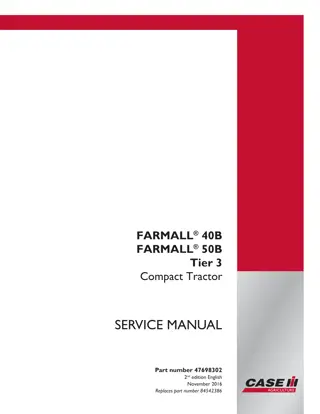
CASE IH FARMALL 40B Tier 3 Compact Tractor Service Repair Manual Instant Download
Please open the website below to get the complete manualnn// n
Download Presentation

Please find below an Image/Link to download the presentation.
The content on the website is provided AS IS for your information and personal use only. It may not be sold, licensed, or shared on other websites without obtaining consent from the author. Download presentation by click this link. If you encounter any issues during the download, it is possible that the publisher has removed the file from their server.
E N D
Presentation Transcript
FARMALL 40B FARMALL 50B Tier 3 Compact Tractor SERVICE MANUAL Part number 47698302 2nd edition English November 2016 Replaces part number 84542386 Printed in U.S.A. 2016 CNH Industrial America LLC. All Rights Reserved. Case IH is a trademark registered in the United States and many other countries, owned by or licensed to CNH Industrial N.V., its subsidiaries or affiliates.
SERVICE MANUAL Farmall 40B Farmall 50B 47698302 04/11/2016 EN
Link Product / Engine Product Market Product North America North America Engine Farmall 40B Farmall 50B S4Q2 S4Q2 47698302 04/11/2016
https://www.ebooklibonline.com Hello dear friend! Thank you very much for reading. Enter the link into your browser. The full manual is available for immediate download. https://www.ebooklibonline.com
Contents INTRODUCTION Engine....................................................................................... 10 [10.001] Engine and crankcase ............................................................. 10.1 [10.202] Air cleaners and lines .............................................................. 10.2 [10.206] Fuel filters .......................................................................... 10.3 [10.218] Fuel injection system............................................................... 10.4 [10.304] Engine lubrication system.......................................................... 10.5 [10.400] Engine cooling system ............................................................. 10.6 Clutch ....................................................................................... 18 [18.100] Clutch mechanical release control ................................................. 18.1 [18.110] Clutch and components ............................................................ 18.2 [18.112] Slip clutch or flywheel damper ..................................................... 18.3 Transmission.............................................................................. 21 [21.114] Mechanical transmission ........................................................... 21.1 [21.140] Mechanical transmission internal components..................................... 21.2 Front axle system ....................................................................... 25 [25.100] Powered front axle ................................................................. 25.1 [25.102] Front bevel gear set and differential ............................................... 25.2 [25.108] Final drive hub, steering knuckles, and shafts ..................................... 25.3 [25.310] Final drives......................................................................... 25.4 Rear axle system........................................................................ 27 [27.106] Rear bevel gear set and differential................................................ 27.1 [27.120] Planetary and final drives .......................................................... 27.2 Hydrostatic drive......................................................................... 29 [29.100] Transmission and steering hydrostatic control..................................... 29.1 [29.202] Hydrostatic transmission ........................................................... 29.2 47698302 04/11/2016
[29.218] Pump and motor components...................................................... 29.3 Power Take-Off (PTO)................................................................. 31 [31.101] Rear mechanical control ........................................................... 31.1 [31.104] Rear electro-hydraulic control...................................................... 31.2 [31.114] Two-speed rear Power Take-Off (PTO) ............................................ 31.3 [31.120] Central Power Take-Off (PTO) ..................................................... 31.4 Brakes and controls .................................................................... 33 [33.110] Parking brake or parking lock ...................................................... 33.1 [33.120] Mechanical service brakes......................................................... 33.2 Hydraulic systems....................................................................... 35 [35.000] Hydraulic systems.................................................................. 35.1 [35.104] Fixed displacement pump.......................................................... 35.2 [35.114] Three-point hitch control valve ..................................................... 35.3 [35.116] Three-point hitch cylinder .......................................................... 35.4 [35.204] Remote control valves ............................................................. 35.5 [35.300] Reservoir, cooler, and filters........................................................ 35.6 [35.350] Safety and main relief valves ...................................................... 35.7 [35.355] Hydraulic hand control ............................................................. 35.8 Hitches, drawbars, and implement couplings.................................. 37 [37.100] Drawbars and towing hitches ...................................................... 37.1 [37.108] Rear three-point hitch external controls............................................ 37.2 [37.110] Rear three-point hitch .............................................................. 37.3 Steering..................................................................................... 41 [41.101] Steering control .................................................................... 41.1 [41.106] Tie rods............................................................................. 41.2 [41.200] Hydraulic control components...................................................... 41.3 [41.216] Cylinders ........................................................................... 41.4 47698302 04/11/2016
Wheels...................................................................................... 44 [44.511] Front wheels........................................................................ 44.1 [44.520] Rear wheels........................................................................ 44.2 Electrical systems....................................................................... 55 [55.000] Electrical system ................................................................... 55.1 [55.010] Fuel injection system............................................................... 55.2 [55.011] Fuel tank system ................................................................... 55.3 [55.012] Engine cooling system ............................................................. 55.4 [55.013] Engine oil system .................................................................. 55.5 [55.031] Parking brake electrical system.................................................... 55.6 [55.048] Rear Power Take-Off (PTO) control system ....................................... 55.7 [55.100] Harnesses and connectors......................................................... 55.8 [55.201] Engine starting system............................................................. 55.9 [55.202] Cold start aid ..................................................................... 55.10 [55.302] Battery............................................................................ 55.11 [55.404] External lighting .................................................................. 55.12 [55.405] External lighting switches and relays ............................................ 55.13 [55.408] Warning indicators, alarms, and instruments .................................... 55.14 [55.525] Cab engine controls.............................................................. 55.15 [55.610] Ground speed control ............................................................ 55.16 [55.640] Electronic modules............................................................... 55.17 Platform, cab, bodywork, and decals............................................. 90 [90.100] Engine hood and panels ........................................................... 90.1 [90.110] Operator platform less cab ......................................................... 90.2 [90.114] Operator protections ............................................................... 90.3 [90.116] Fenders and guards................................................................ 90.4 [90.120] Mechanically-adjusted operator seat............................................... 90.5 47698302 04/11/2016
INTRODUCTION 47698302 04/11/2016 1
INTRODUCTION Safety rules Personal safety This is the safety alert symbol. It is used to alert you to potential personal injury hazards. Obey all safety messages that follow this symbol to avoid possible death or injury. Throughout this manual you will find the signal words DANGER, WARNING, and CAUTION followed by special in- structions. These precautions are intended for the personal safety of you and those working with you. Read and understand all the safety messages in this manual before you operate or service the machine. DANGER indicates a hazardous situation that, if not avoided, will result in death or serious injury. WARNING indicates a hazardous situation that, if not avoided, could result in death or serious injury. CAUTION indicates a hazardous situation that, if not avoided, could result in minor or moderate injury. FAILURE TO FOLLOW DANGER, WARNING, AND CAUTION MESSAGES COULD RESULT IN DEATH OR SERIOUS INJURY. Machine safety NOTICE: Notice indicates a situation that, if not avoided, could result in machine or property damage. Throughout this manual you will find the signal word Notice followed by special instructions to prevent machine or property damage. The word Notice is used to address practices not related to personal safety. Information NOTE: Note indicates additional information that clarifies steps, procedures, or other information in this manual. Throughout this manual you will find the word Note followed by additional information about a step, procedure, or other information in the manual. The word Note is not intended to address personal safety or property damage. 47698302 04/11/2016 6
INTRODUCTION Safety rules - Ecology and the environment Soil, air, and water quality is important for all industries and life in general. When legislation does not yet rule the treatment of some of the substances that advanced technology requires, sound judgment should govern the use and disposal of products of a chemical and petrochemical nature. Familiarize yourself with the relative legislation applicable to your country, and make sure that you understand this legislation. Where no legislation exists, obtain information from suppliers of oils, filters, batteries, fuels, anti-freeze, cleaning agents, etc., with regard to the effect of these substances on man and nature and how to safely store, use, and dispose of these substances. Helpful hints Avoid the use of cans or other inappropriate pressurized fuel delivery systems to fill tanks. Such delivery systems may cause considerable spillage. In general, avoid skin contact with all fuels, oils, acids, solvents, etc. Most of these products contain substances that may be harmful to your health. Modern oils contain additives. Do not burn contaminated fuels and or waste oils in ordinary heating systems. Avoid spillage when you drain fluids such as used engine coolant mixtures, engine oil, hydraulic fluid, brake fluid, etc. Do not mix drained brake fluids or fuels with lubricants. Store all drained fluids safely until you can dispose of the fluids in a proper way that complies with all local legislation and available resources. Do not allow coolant mixtures to get into the soil. Collect and dispose of coolant mixtures properly. The air-conditioning system contains gases that should not be released into the atmosphere. Consult an air-condi- tioning specialist or use a special extractor to recharge the system properly. Repair any leaks or defects in the engine cooling system or hydraulic system immediately. Do not increase the pressure in a pressurized circuit as this may lead to a component failure. Protect hoses during welding. Penetrating weld splatter may burn a hole or weaken hoses, allowing the loss of oils, coolant, etc. Battery recycling Batteries and electric accumulators contain several substances that can have a harmful effect on the environment if the batteries are not properly recycled after use. Improper disposal of batteries can contaminate the soil, groundwater, and waterways. CASE IH strongly recommends that you return all used batteries to a CASE IH dealer, who will dispose of the used batteries or recycle the used batteries properly. In some countries, this is a legal requirement. Mandatory battery recycling NOTE: The following requirements are mandatory in Brazil. Batteries are made of lead plates and a sulfuric acid solution. Because batteries contain heavy metals such as lead, CONAMA Resolution 401/2008 requires you to return all used batteries to the battery dealer when you replace any batteries. Do not dispose of batteries in your household garbage. Points of sale are obliged to: Accept the return of your used batteries Store the returned batteries in a suitable location Send the returned batteries to the battery manufacturer for recycling 47698302 04/11/2016 8
INTRODUCTION Safety rules - Personal safety General safety rules Read this manual carefully before starting, using carrying out maintenance, refueling or performing any other type of operation on the tractor. Read all the safety decals on the tractor and follow the instructions thereon before starting, operating, refueling or carrying out maintenance on the tractor. Promptly replace any decals that are damaged, lost or illegible. Clean the decals if they are covered by mud or debris. The tractor must only be used by responsible personnel, trained in tractor use and authorized to operate the tractor. Use caution when operating the tractor on slopes. Raised equipment, full tanks and other loads will change the center of gravity of the tractor. The tractor can tip or roll over when near ditches and embankments or uneven surfaces. Avoid using the tractor in unsuitable physical conditions, stop work instead. Never permit anyone other than the operator to ride on the tractor. Never operate the tractor under the influence of alcohol, drugs, or while otherwise impaired. When digging or using ground engaging attachments be aware of buried cables. Contact local utilities to determine the locations of services. Pay attention to overhead power lines and hanging obstacles. High voltage lines may require significant clearance for safety. Hydraulic oil or diesel fuel leaking under pressure can penetrate the skin, causing serious injury or infection. DO NOT use your hand to check for leaks. Use a piece of cardboard or paper. Stop engine, remove key and relieve the pressure before connecting or disconnecting fluid lines. Make sure all components are in good condition and tighten all connections before starting the engine or pressur- izing the system. If hydraulic fluid or diesel fuel penetrates the skin, seek medical attention immediately. Continuous long term contact with hydraulic fluid may cause skin cancer. Avoid long term contact and wash the skin promptly with soap and water. Before removing any hydraulic tubing, check that the system is not pressurized. Do not alter the calibration of the pressure relief valves in the various hydraulic circuits (steering, hydraulic lift, auxiliary distributors, etc.). Keep clear of moving parts. Loose clothing, jewelry, watches, long hair, and other loose or hanging items can become entangled in moving parts. Wear protective equipment when appropriate. DO NOT attempt to remove material from any part of the tractor while it is being operated or components are in motion. Make sure all guards and shields are in good condition and properly installed before operating the tractor. Never operate the tractor with shields removed. Always close access doors or panels before operating the tractor. Enter and leave the tractor using the steps and handles provided. Dirty or slippery steps, ladders, walkways, and platforms can cause falls. Make sure these surfaces remain clean and clear of debris. A person or pet within the operating area of a tractor can be struck or crushed by the tractor or its equipment. DO NOT allow anyone to enter the work area. Raised equipment and/or loads can fall unexpectedly and crush persons underneath. Never allow anyone to enter the area underneath raised equipment during operation. Never operate engine in enclosed spaces as harmful exhaust gases may build up. 47698302 04/11/2016 9
INTRODUCTION Before starting the tractor, be sure that all controls are in neutral or park lock position. Before starting the engine, make sure that all attached implements are lowered to the ground. Start the engine only from the operator s seat. If the safety start switch is bypassed, the engine can start with the transmission in gear. Do not connect or short across terminals on the starter solenoid. Attach jumper cables as described in the manual. Starting in gear may cause death or serious injury. Always keep windows, mirrors, all lighting, and Slow Moving Vehicle (SMV) emblem clean to provide the best possible visibility while operating the tractor. Operate controls only when seated in the operator s seat, except for those controls expressly intended for use from other locations. 47698302 04/11/2016 10
SERVICE MANUAL Engine Farmall 40B Farmall 50B 47698302 04/11/2016 10
Engine - Engine and crankcase Engine - Remove - Separating the tractor at the clutch housing/engine Farmall 40B Farmall 50B NA Platform - With ROPS NA Platform - With ROPS 1. Chock all four wheels so that the tractor cannot move. 2. Disconnect negative (-) battery cable (1). 1 93100929 3. Disconnect headlight wire harness. 4. Disassemble the pin (3) at the hood strut and wire har- ness connector. 5. Remove hinge cover and M8 x 16mm bolt (2). 6. Carefully remove hood (1). 2 93102238 7. Disconnect the main and engine wire harnesses. 8. Turn off fuel supply at the filter (1), and then disconnect fuel hose. 3 93102239 47698302 04/11/2016 10.1 [10.001] / 3
Engine - Engine and crankcase 9. Position a drain pan to collect drain oil and unfasten clamps (1). 10. Disassemble suction tube assembly (2). 4 93102240 11. Remove the knobs (2) on both rear cover halves (1) and remove. 5 93102241 12. Remove the mat (1). 13. Remove the M8 nuts and bolts and remove cover (2). 6 93102242 14. Remove the bolts (2) and remove the pedals (1). 7 93102243 47698302 04/11/2016 10.1 [10.001] / 4
Engine - Engine and crankcase 15. Remove the seven M8 and one M24 bolts (3). 16. Remove right-hand step (1) and left-hand step (2). 8 93102244 17. Disconnect the front high pressure tube (1). 9 93102245 18. Disconnect steering hoses (2) and tubes (1). 10 93102246 19. Disconnect brake the rod (1), HST or gear transmis- sion. 11 93102247 47698302 04/11/2016 10.1 [10.001] / 5
Engine - Engine and crankcase 20. Disconnect brake rod (2) on the right-hand side and clutch rod on the left-hand side; gear transmission only. 12 93102248 (1) Clutch pedal Brake rod connection; HST transmission 1. Disassemble the brake rods as shown in figure 13 . 13 93102250 (1) Pedal (2) Arm assembly (3) Arm (4) Rod 2. Remove the bolts (2) securing frame (1) to fire wall, and remove frame. 14 93102251 47698302 04/11/2016 10.1 [10.001] / 6
Engine - Engine and crankcase 3. Remove the fire wall (1) with the aid of a hoist. 15 93102252 4. Disconnect and remove the oil cooler (1) and related parts, as shown in figure 16. 16 93102253 Secure the tractor for separation: 1. Attach a chain sling (2) to the two hoist eyes on the engine: One located on the left-hand side above the exhaust manifold, the other on the right-hand side to the rear of the injector rail. 2. Attach a suitable hoist to the chain sling. 3. Roll a floor jack (1) under the tractor from the rear of the tractor, and place under the clutch housing. Raise the jack enough to support the drive train. 17 93105782 47698302 04/11/2016 10.1 [10.001] / 7
Engine - Engine and crankcase 4. Remove the eight M12 bolts (2) holding the engine (1) and transmission (3), while checking front wheel drive shaft for separation from the transmission. 18 93102254 19 93105783 NOTE: The hoist and/or the floor jack may need to be raised or lowered to allow the separation of the engine from the clutch housing. 5. Carefullyrollthedrivetrainawayfromtheengine, using the floor jack for support. 47698302 04/11/2016 10.1 [10.001] / 8
Engine - Engine and crankcase Engine - Remove - Separating the tractor at the center case/rear axle Farmall 40B Farmall 50B NA Platform - With ROPS NA Platform - With ROPS 1. Block or jack both rear axle shaft housing so that the rear tires are lifted off the ground. 2. Use a suitable chain sling and hoist to support, but not lift, the engine and front of the tractor. 3. Drain transmission oil completely. 4. Remove rear tires. 5. Support rear axles. 1 20103245 6. Remove the M8 bolts (1) securing fenders (2), and re- move fenders. 2 93102256 7. Remove M10x25 bolts (1), and remove seat (2) from center cover (3). 3 93102257 47698302 04/11/2016 10.1 [10.001] / 9
Engine - Engine and crankcase 8. Remove mat (1). 9. Remove securing bolt and nuts (2), and remove cover (3). 4 93102258 10. Remove control knobs and grips (1). 11. Disconnect wire harness from PTO and lift control. 12. Remove M8x16 bolts securing lever guides (2). 5 93102259 13. Remove snap ring (1) and disconnect the parking brake cable (2). 14. Disconnect all rods. 6 93102260 (A) Center cover 15. Position a drain pan beneath hydraulic suction tube (1) to collect oil. 16. Disassemble hydraulic suction tube, unfastening clamps (2). (A) PTO valve (B) Pump (C) Front valve 7 93102261 47698302 04/11/2016 10.1 [10.001] / 10
Engine - Engine and crankcase 17. Remove cotter pin (1) at the end of drop speed control arm (2). 8 93102262 18. Remove M16 bolts (1), and remove center cover (2). 9 93102263 19. Disconnect brake rods (1). 10 93102264 20. Disconnect fuel lines (1), and harness (2). 11 93102265 47698302 04/11/2016 10.1 [10.001] / 11
Engine - Engine and crankcase 21. Remove M12 bolts (1), and separate cases. 12 93102266 47698302 04/11/2016 10.1 [10.001] / 12
Engine - Fuel filters Fuel filters - Replace fuel filter NOTE: Change the diesel fuel filter (1) after the first 50 hours of operation, then following every 500 operating hours thereafter. 1 NHIL13CT01068AA 1. Loosen fuel filter drain plug (2) and drain fuel from the filter. 2. Disconnect the electrical connector from the fuel filter sensor (3). 3. Remove the fuel filter element (4) from the filter base 4. Remove the fuel filter sensor (3) from the original ele- ment and install sensor with O-ring (5) onto new ele- ment. 5. Install new element onto the filter base. 6. Connect electrical connector to the fuel filter sensor. 2 93100920 7. Tighten fuel filter drain plug. 8. Bleed the air from the fuel filter, by pressing the manual fuel feed pump (6) several times. The manual feed pump will bleed the air back to the fuel tank. There is no need to open any bleed ports in the fuel system. 3 NHIL13CT01251AA 47698302 04/11/2016 10.3 [10.206] / 4
Engine - Fuel filters Fuel filters - Remove - Fuel filter sensor Farmall 40B Farmall 50B NA Platform - With ROPS NA Platform - With ROPS 1. Disconnect the sensor electrical connector (3) from the tractor wiring harness. 1 761002933 2. Rotate sensor (2) counterclockwise until sensor is free from the bottom of the fuel filter. 3. Inspect O-ring (1) for damage and replace if necessary. 47698302 04/11/2016 10.3 [10.206] / 5
Engine - Fuel filters Fuel filters - Test - Fuel filter sensor Farmall 40B Farmall 50B NA Platform - With ROPS NA Platform - With ROPS Float in "TOP" position 1. Install an ohmmeter across the terminals of the sensor connector. 1 76110376 2. Move the float (1) to the full top position. 3. There should be continuity across the terminals. 4. If continuity reading does not match as stated in the test procedure, replace the sensor. Float in "BOTTOM" position 1. Install an ohmmeter across the terminals of the sensor connector. 2 76110377 2. Move the float (1) to the full bottom position. 3. There should not be any continuity across the termi- nals. 4. If continuity reading does not match as stated in the test procedure, replace the sensor. 47698302 04/11/2016 10.3 [10.206] / 6
Engine - Fuel filters Fuel filters - Install - Fuel filter sensor Farmall 40B Farmall 50B NA Platform - With ROPS NA Platform - With ROPS 1. Install O-ring (1). 2. Thread sensor (2) into the bottom of the fuel filter. 3. Connect sensor electrical connector (3) with tractor wiring harness. 1 761002933 47698302 04/11/2016 10.3 [10.206] / 7
Engine - Fuel injection system Injection pump - Timing adjust Farmall 40B Farmall 50B NA Platform - With ROPS NA Platform - With ROPS 1. Remove the engine valve cover (1). 1 NHIL13CT00757AA 2. Remove the oil fill cover (2) from the timing gear hous- ing to gain access to the injection pump gear (3). 2 NHIL13CT00756AA 3 NHIL12ENG0079AA 47698302 04/11/2016 10.4 [10.218] / 12
Engine - Fuel injection system 3. Rotate the engine crankshaft clockwise until both #1 cylinder valve rockers (1) and push rods (2) are loose. This indicates compression stroke of #1 cylinder. 4. Removerockerarmassembly(3)fromtheenginecylin- der head. 4 NHIL13CT00761AA 5 NHIL13CT00758AA 5. Remove the valve keepers and spring from one of the #1 cylinder valves. 6. Push valve (1) downwards until valve contacts the top of the piston. 6 NHIL13CT00760AA 7. Install a dial indicator (2) of top of the valve stem. 7 NHIL13CT00759AA 47698302 04/11/2016 10.4 [10.218] / 13
Engine - Fuel injection system NOTICE: Read the following procedure before removing the injection pump from the engine. 8. Rotate the crankshaft clockwise until the V V timing marks (1) on the injection pump gear are at approxi- mately 8 o clock position and are in full tooth engage- ment with the idler gear (2). Mark the idler gear tooth (A) with a paint pen at this time. 8 NHIL12ENG0075AA 9. Rotate the crankshaft clockwise until the valve travel shown on the dial indicator (1) reverses direction. The point at when the valve direction reverses is top dead center or TDC of the #1 piston travel. 9 NHIL13CT00761AA 10 NHIL13CT00759AA 10. Remove injector lines (1) and head bolt (2) from the rear of the fuel injection pump. 11 NHIL13CT00755AA 47698302 04/11/2016 10.4 [10.218] / 14
Engine - Fuel injection system 11. Install special adapter with dial indicator (1) tool # CAS1745 into the rear of the injection pump. 12. Pre load the dial indicator approximately 2.5 mm (0.098 in) . 12 NHIL13CT00763AA 13 NHIL13CT00764AA 13. Rotate the crankshaft counter-clockwise approxi- mately 30 until the dial indicator on the injection pump STOPS moving. Stop rotating the crankshaft at this point. 14 NHIL13CT00761AA 14. Adjust the dial indicator to ZERO at this time. 15 NHIL13CT00764AA 47698302 04/11/2016 10.4 [10.218] / 15
Suggest: If the above button click is invalid. Please download this document first, and then click the above link to download the complete manual. Thank you so much for reading
Engine - Fuel injection system 15. Rotate the crankshaft pulley clockwise until the until top dead center (TDC) of #1 cylinder is obtained. 16 NHIL13CT00761AA 16. Loosen the injection pump mounting bolts and rotate the pump to adjust pump timing until total dial indica- tor movement (A) from the ZERO setting reads the following: 17 NHIL13CT00765AA 18 NHIL13CT00764AA Engine model Tractor model Dial indicator total movement (A) 1.05mm (0.041 in) 0.945mm (0.037 in) Boomer 40 Boomer 50 S4QL-D (41 HP) S4QL (47 HP) Engine model Tractor model Injection pump timing specification After top dead center 1 (ATDC1) Before top dead center 1 (BTDC1) Boomer 40 Boomer 50 S4QL-D (41 HP) S4QL (47 HP) 47698302 04/11/2016 10.4 [10.218] / 16
https://www.ebooklibonline.com Hello dear friend! Thank you very much for reading. Enter the link into your browser. The full manual is available for immediate download. https://www.ebooklibonline.com

