Case IH 1020 Flexible Cutter Bar Grain Header Operator’s Manual Instant Download (Publication No.84216710)
Please open the website below to get the complete manualnn//
Download Presentation

Please find below an Image/Link to download the presentation.
The content on the website is provided AS IS for your information and personal use only. It may not be sold, licensed, or shared on other websites without obtaining consent from the author. Download presentation by click this link. If you encounter any issues during the download, it is possible that the publisher has removed the file from their server.
E N D
Presentation Transcript
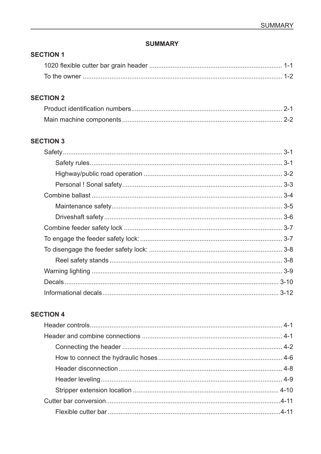
SUMMARY SUMMARY SECTION 1 1020 flexible cutter bar grain header .......................................................................... 1-1 To the owner ............................................................................................................... 1-2 SECTION 2 Product identification numbers .................................................................................... 2-1 Main machine components ......................................................................................... 2-2 SECTION 3 Safety .......................................................................................................................... 3-1 Safety rules ........................................................................................................... 3-1 Highway/public road operation ............................................................................. 3-2 Personal ! Sonal safety ......................................................................................... 3-3 Combine ballast .......................................................................................................... 3-4 Maintenance safety............................................................................................... 3-5 Driveshaft safety ................................................................................................... 3-6 Combine feeder safety lock ........................................................................................ 3-7 To engage the feeder safety lock: ............................................................................... 3-7 To disengage the feeder safety lock: .......................................................................... 3-8 Reel safety stands ................................................................................................ 3-8 Warning lighting .......................................................................................................... 3-9 Decals ....................................................................................................................... 3-10 Informational decals .................................................................................................. 3-12 SECTION 4 Header controls ........................................................................................................... 4-1 Header and combine connections .............................................................................. 4-1 Connecting the header ......................................................................................... 4-2 How to connect the hydraulic hoses ..................................................................... 4-6 Header disconnection ........................................................................................... 4-8 Header leveling ..................................................................................................... 4-9 Stripper extension location ................................................................................. 4-10 Cutter bar conversion .................................................................................................4-11 Flexible cutter bar ................................................................................................4-11
SUMMARY Rigid cutter bar ................................................................................................... 4-14 SECTION 5 Pictorial index .............................................................................................................. 5-1 Reel operation and adjustments ........................................................................... 5-1 Reel adjustments ........................................................................................................ 5-4 Reel speed............................................................................................................ 5-5 Reel height............................................................................................................ 5-5 Adjusting minimum reel height.............................................................................. 5-7 Auger lift link position ............................................................................................ 5-8 Reel fore/aft position ............................................................................................. 5-9 Standing or tall crops ............................................................................................ 5-9 Down or short crops.............................................................................................. 5-9 Ground speed ....................................................................................................... 5-9 Hydraulic fore/aft adjustment .............................................................................. 5-10 Reel position for crop conditions ................................................................................5-11 Tine pitch adjustment .......................................................................................... 5-13 Tine pitch adjustment .......................................................................................... 5-14 Auxiliary pickup tine - plastic (if equipped) ............................................................... 5-15 Auxiliary pickup tine - steel (if equipped) ................................................................. 5-16 Pictorial index ............................................................................................................ 5-17 Header and cutter bar operation and adjustments ............................................. 5-17 Header height operation ........................................................................................... 5-21 Manual header height control ............................................................................. 5-21 Automatic header height control ......................................................................... 5-22 Instructions for setting the sensor platform 1020 ...................................................... 5-23 Instructions to optimize 1020 header sensors for 2688 and 2799 combines ..... 5-23 Header potentiometer calibration........................................................................ 5-26 Automatic header height control operation ......................................................... 5-28 Header height indicator....................................................................................... 5-29 Flexible cutter bar operation ..................................................................................... 5-31 Cutter bar flotation springs ........................................................................................ 5-32 Ground pressure too high ................................................................................... 5-32 Ground pressure too low .................................................................................... 5-32 Flotation spring adjustment................................................................................. 5-33
SUMMARY Runner and sensor linkage inspection................................................................ 5-35 Rigid cutter bar operation .......................................................................................... 5-37 Dividers ..................................................................................................................... 5-38 Rear divider adjustment ...................................................................................... 5-39 Divider linkage adjustment.................................................................................. 5-40 Divider spring adjustment ................................................................................... 5-41 Knife drive pulley ....................................................................................................... 5-42 Auxiliary skid shoes (if equipped) ............................................................................. 5-43 Grain lifters (if equipped) ........................................................................................... 5-43 Extra knife storage .................................................................................................... 5-44 Pictorial index ............................................................................................................ 5-45 Auger operation and adjustments ....................................................................... 5-45 Auger adjustments .................................................................................................... 5-48 Auger clearances ................................................................................................ 5-48 Auger clearance to header bottom ..................................................................... 5-49 Auger clearance to stripper................................................................................. 5-51 Auger fore/aft adjustment ................................................................................... 5-52 Auger speed ....................................................................................................... 5-54 Heavy or bulky crops .......................................................................................... 5-54 Light or short crops ............................................................................................. 5-54 Auger drive sprocket - removal and installation .................................................. 5-55 Auger flight extensions - long (if equipped) ........................................................ 5-58 Auger flight extensions - short (if equipped) ....................................................... 5-60 Unplugging the auger ......................................................................................... 5-64 Method A - raise auger with auger lift links ......................................................... 5-64 Method B - reverse auger with feeder reverser .................................................. 5-65 Method C - reverse the auger manually ............................................................. 5-66 Auger retractable fingers .................................................................................... 5-67 Troubleshooting ........................................................................................................ 5-68 Field operation and troubleshooting notes: ........................................................ 5-75 SECTION 6 Service intervals .......................................................................................................... 6-1 After the first 10 hours .......................................................................................... 6-1 Every 10 hours...................................................................................................... 6-1
https://www.ebooklibonline.com Hello dear friend! Thank you very much for reading. Enter the link into your browser. The full manual is available for immediate download. https://www.ebooklibonline.com
SUMMARY Every 50 hours...................................................................................................... 6-2 Every 100 horas.................................................................................................... 6-3 SECTION 7 Lubrication .................................................................................................................. 7-1 General service information .................................................................................. 7-1 Sealed bearings .................................................................................................... 7-1 Lubrication fittings ................................................................................................. 7-1 Chains................................................................................................................... 7-1 Knife...................................................................................................................... 7-1 Knife drive box ...................................................................................................... 7-2 Drive shaft u-joint(s) .............................................................................................. 7-4 Pto drive shaft ball collar and alignment coupler .................................................. 7-4 Lubrication chart ......................................................................................................... 7-5 Grease fittings ............................................................................................................. 7-6 10 hours ................................................................................................................ 7-6 Driveshaft components ....................................................................................... 7-10 Chain lubrication ................................................................................................. 7-10 Other lubrication ..................................................................................................7-11 SECTION 8 Auger finger replacement ............................................................................................ 8-1 Auger slip clutch .......................................................................................................... 8-2 Automatic header height control ................................................................................. 8-4 Component identification ............................................................................................ 8-4 Automatic header height control adjustment ........................................................ 8-5 Header potentiometer adjustment ........................................................................ 8-7 Sensor tube and feeler adjustment ....................................................................... 8-8 Header height indicator adjustment .....................................................................8-11 Sensor tube return spring ......................................................................................... 8-12 76.2 mm (3 inch) knife (if equipped) ................................................................... 8-13 Knife hold down clip adjustment ......................................................................... 8-13 Guard alignment ................................................................................................. 8-14 Hold down clip adjustment .................................................................................. 8-14 Knife head adjustment ........................................................................................ 8-15
SUMMARY Belts and chains ........................................................................................................ 8-16 Belts - general maintenance ............................................................................... 8-16 Knife drive belt adjustment ................................................................................. 8-17 Chains - general maintenance ............................................................................ 8-18 Connecting link locking spring clip (closed end to travel direction) ........................... 8-18 Auger drive chain adjustments ........................................................................... 8-19 Reel drive chain adjustment ............................................................................... 8-19 Header drain holes .................................................................................................... 8-20 Special tool operated latches .................................................................................... 8-20 Warning lamp bulb replacement ......................................................................... 8-21 SECTION 9 Storing the header ...................................................................................................... 9-1 Removing from storage ............................................................................................... 9-2 Initial start up check list......................................................................................... 9-2 SECTION 10 General specifications ............................................................................................... 10-1 Auger .................................................................................................................. 10-1 Cutter bar ............................................................................................................ 10-1 Header width....................................................................................................... 10-1 Knife.................................................................................................................... 10-1 Reel .................................................................................................................... 10-2 Recommended header size ...................................................................................... 10-2
SECTION 1 SECTION 1 1020 FLEXIBLE CUTTER BAR GRAIN HEADER 2 1 2-C2688-003-06-E NOTE: While seated in the Combine s Operators Seat facing forward, the Left (1) and Right (2) side of the Header are the same as your Left and Right hand. 1-1
TO THE OWNER TO THE OWNER This manual contains important information about the safe operation, adjustment and maintenance of your CASE Grain Header. Refer to the Detail Index at the end of this manual for locating specific items about your machine. DO NOT operate or permit anyone to operate or service this machine until you or the other persons have read this manual. Use only trained operators who have demonstrated the ability to operate and service this machine correctly and safely. This Grain Header, with standard equipment and authorized attachments, is intended to be used with a Combine for harvesting agricultural food grains such as wheat, rice, soybeans, etc. DO NOT use this machine for any application or purpose other than those described in this manual. Consult an authorized dealer or the Case IH on changes, additions or modifications that can be required for this machine to comply with various country regulations and safety requirements. Unauthorized modifications will cause serious injury or death. Anyone making such unauthorized modifications is responsible for the consequences. This Operators Manual is to be stored in the Combine Operators Manual Storage Compartment equipped on your Combine, refer to illustration below. Make sure this manual is complete and in good condition. Contact your dealer to obtain additional manuals. Contact your dealer for any further information or assistance about your machine. Your dealer has Case IH approved service parts. Your dealer has technicians with special training that know the best methods of repair and maintenance for your Grain Header. RD00E064 1-2
SECTION 2 SECTION 2 PRODUCT IDENTIFICATION NUMBERS When ordering parts or when requesting information or assistance always give the following information. 1. Machine Name 87552274 2. Model Number 3. Product Identification Number PLAQCASE-87552274 Write the model and product identification numbers of your Header on the lines below. 1. Model Number... 2. Product Identification Number... IMG_0057 2-1
IDENTIFICATION NUMBERS MAIN MACHINE COMPONENTS 9 2 3 7 1 8 6 5 4 1 2-C2688-003-06-E 1. DIVIDER 4. CUTTER BAR 7. WARNING LAMP 2. AUGER DRIVE (RIGHT SIDE) 5. AUGER 8. REEL SUPPORT ARM 3. PICKUP REEL 6. KNIFE DRIVE (INSIDE) 9. HEADER DRIVESHAFT (REAR OF HEADER) 2-2
SECTION 3 SECTION 3 SAFETY Understand that your safety and the safety of other persons is measured by how you service and operate this machine. Know the positions and operations of all controls before you try to operate. MAKE SURE YOU CHECK ALL CONTROLS IN A SAFE AREA BEFORE STARTING YOUR WORK. READ THIS MANUAL COMPLETELY and make sure you understand the controls. All equipment has a limit. Make sure you understand the stability, and load characteristics of this machine before you start to operate. The safety information given in this manual does not replace safety codes, insurance needs, federal, state and local laws. Make sure your machine has the correct equipment needed by the local laws and regulations. The Case IH is continuing to work for your safety: by making machines with better protection and by giving these rules for safe operation. THIS SAFETY ALERT SYMBOL INDICATES IMPORTANT SAFETY MESSAGES IN THIS MANUAL. WHEN YOU SEE THIS SYMBOL, CAREFULLY READ THE MESSAGE THAT FOLLOWS AND BE ALERT TO THE POSSIBILITY OF DEATH OR SERIOUS INJURY. M171C Safety Rules Before starting engine study Operators Manual safety messages. Read all safety signs on machine. Clear the area of other persons. Learn and practice safe use of controls before operating. It is your responsibility to understand and follow manufacturers instructions on machine operation, service, and to observe pertinent laws and regulations. Operator and Service Manuals may be obtained from your equipment dealer. R103A Always shut OFF engine, remove the key and engage feeder safety lock in position on lift cylinder before working under Header or feeder. Failure to engage feeder safety lock may cause injury or death. M184D Never connect the reel fore/aft hydraulic couplers on the header to each other. This would complete the circuit and allow the reel to slide unexpectedly. M209B 3-1
SAFETY/DECALS ALWAYS turn OFF combine engine and remove the key before servicing the Header. Never under any condi- tions lubricate the header while machine is running. M207C Never make adjustments when Header or machine is running. R208B Header equipped with Automatic Header Height Control - Make sure every one is clear when checking auto- matic Header control. Do not rotate Header height control potentiometer, move ground sensors or rotate height control sensor linkage with feeder running. Rotating potentiometer or actuating height control linkage with feeder running may cause the Header to suddenly raise or lower and can injure the operator or bystanders. ALWAYS make sure working area is clear of other persons, pets, tools, etc. before you start operating this machine. NEVER allow anybody in work area during machine operation. ALWAYS sound horn before starting the Combine. Highway/Public Road Operation Understand and comply with state and local laws governing highway safety regulations concerning transport- ing a Combine with a Header attached. Maintain complete control of the Combine. Make sure the Combine brake pedals are connected with the brake latch. Make sure road lamps and beacons are in working order and comply with local laws. Check clearance before going under electric lines, crossing bridges or entering buildings. On narrow or hilly roads or blind curves - where motor vehicles can suddenly come upon slow moving traffic, extra caution should be exercised, such as having two vehicles proceed/follow the Combine to warn and/or removing the Header and transport separately. 3-2
SECTION 3 Personal ! sonal Safety Throughout this manual and on the machine s safety decals, you will find precautionary statements: DANGER, WARNING or CAUTION followed by specific instructions or ISO two panel safety pictorial symbols. These pre- cautions are intended for your personal safety. Failure to follow the DANGER, WARNING or CAUTION instructions may result in death or serious bodily injury. DANGER, WARNING or CAUTION are defined as follows: DANGER: Indicates an immediate hazardous situation that, if not avoided, will result in death or serious injury. The color associated with Danger is RED. WARNING: Indicates a potentially hazardous situation that, if not avoided, could result in death or serious injury. The color associated with Warning is ORANGE. CAUTION: Indicates a potentially hazardous situation that, if not avoided, may result in minor or moderate injury. It may also be used to alert against unsafe practices. The color associated with Caution is YELLOW. ISO two panel pictorial symbol decals are defined as follows: The first panel indicates the nature of the hazard. The second panel indicates the appropriate avoidance of the hazard. Background color is YELLOW. Prohibition symbols such as and if used, are RED. PARE 3-3
SAFETY/DECALS COMBINE BALLAST Make sure your Combine has proper ballasting. Large and/or heavy Headers may alter the center of gravity of your machine. This will affect your operating, steering and braking performance. Refer to your Combine Operators Manual for the correct ballast required for your application. RS00D050 3-4
SECTION 3 Maintenance Safety Always keep safety and informational decals clean and visible. Replace decals that are damaged, lost, painted over or can not be read. When assembling, operating or servicing the machine, wear protective clothing and personal safety devices that are necessary for the particular procedure. Some personal safety devices that may be necessary are protective shoes, face and/or eye protection, hard hat, heavy gloves, filter mask and hearing protection. Do Not wear jewelry or loose fitting clothing that may get caught in moving parts. Always wear close fitting clothing. Keep hands, feet, clothing and hair away from moving parts. Never attempt to clear obstructions or objects from the machine while the Combine engine is running. ALWAYS SHUT OFF Combine engine and remove the key. When servicing the machine, always have the machine on a firm level surface. If shields or guards are re- moved or opened for service, always replace shields or guards before operating the machine. Never operate machine with missing or open shields or guards. Keep the area used for servicing the machine clean and dry. Wet or oily floors are slippery. Wet spots can be dangerous when working with electrical equipment. Be sure all electrical outlets and tools are properly grounded. RH99E030 3-5
SAFETY/DECALS Driveshaft Safety Make sure safety chains are attached during field operation. Make sure outer shield can rotate freely. Make sure all shields are in place after servicing. NEVER operate machine with shields removed. Replace any damaged shields. DO NOT clean, adjust, unclog or service the driveshaft when Combine engine is running. Always shut OFF engine and remove the key before cleaning, adjusting, unclogging or servicing the driveshaft. Replace worn or missing shields. DO NOT make any modifications to the driveshaft.. Make sure driveshaft is attached properly before starting field operation. If field operation is at night or in poor visibility conditions, illuminate the driveshaft area during installation of the driveshaft. Do Not wear jewelry, long free hanging hair or loose fitting clothing that may get caught in moving parts. Always wear close fitting clothing. Keep hands, feet, clothing and hair away from moving parts. 1 RH00J026 The telescoping tubes (shields) must always overlap (1) by a least 1/3 of their length. DO NOT extend the driveshaft past the maximum length during transportation or operation. NEVER use the safety chains to support the driveshaft for storage. ALWAYS store the driveshaft in its proper storage position or holder. DO NOT step or stand on driveshaft. When field operation is complete, shut OFF the engine, remove the key and wait until driveshaft stops before leaving the operators seat. 3-6
SECTION 3 COMBINE FEEDER SAFETY LOCK The Combine feeder left lift cylinder is equipped with a safety lock. The safety lock is used to prevent ac- cidental lowering of the feeder or Header. ALWAYS engage the feeder safety lock before working under the feeder or Header. RD01H172 CASE COMBINE FEEDER SAFETY LOCK LIFT CYLINDER DECAL 144379A1 TO ENGAGE THE FEEDER SAFETY LOCK: 1. Raise the feeder to the maximum height. 2. Pull spring loaded latch pin to release feeder lock. 3. Lower the feeder lock over the left lift cylinder rod. ATEN O: Always shut OFF engine, remove the key and engage feeder safety lock in position on lift cylinder before working under Header or feeder. Failure to engage feeder safety lock may cause injury or death. M184D 3-7
SAFETY/DECALS TO DISENGAGE THE FEEDER SAFETY LOCK: 1. Raise the feeder to maximum height. 2. Rotate the feeder lock up off of the lift cylinder rod. Engage spring loaded latch pin to the feeder lock. RD01H176 Reel Safety Stands Each reel lift cylinder is equipped with a safety stand. ALWAYS engage the safety stand on BOTH reel lift cylinders before working around or under a raised reel. To engage the safety stands (1), raise the reel to the highest position and lower the safety stand on the cylinders. Secure the safety stand to the cylinder rod with the cylinder adjusting rod (2) and hairpin (3). 1 3 2 IMG_0097 To disengage the safety stands, raise the reel to the highest position. Remove the cylinder adjusting rod and hairpin from the safety stand. Raise the safety stand and engage the holder (4) for the safety stand. Install the adjusting rod and hairpin in the cylinder rod. 4 1 IMG_0099 3-8
SECTION 3 WARNING LIGHTING The Header is equipped with road transport warning lamps that operate the same as similar lamps on the Combine lighting system. 1 RD00H088 2 RD00H079 When connecting the Header to the Combine, make sure to connect the Combine electrical harness to the Header. The connector is located near the hydraulic hose quick coupling. IMG_0073 3-9
Suggest: If the above button click is invalid. Please download this document first, and then click the above link to download the complete manual. Thank you so much for reading
SAFETY/DECALS DECALS Safety Decals are placed on your machine as a guide for your safety. Walk around your machine and note the content and location of these decals before operating your machine. IMPORTANT: Install new decals if the old decals are destroyed, lost, painted over or cannot be read. When parts are replaced that have decals, make sure you install a new decal with each new part NOTE: New decals are available from your dealer. NOVO NOVO NOTE: Decal 1326528C is located on the drive shaft telescoping members under the plastic tubular shields. NOTE: Decal 1326528C is in English. This decal is a safety warning that indicates an immediate hazardous situation which, if not avoided, will result in death or serious injury. DANGER - Shield Missing, Do Not Operate. Drive Line Shield Warning Decal and Header Crush Danger Decal 1 2 87027712 237175A1 Localization (1): Rear panel of the platform. Localization (2) : Rear panel of the platform and left and right driveshafts. 3-10
https://www.ebooklibonline.com Hello dear friend! Thank you very much for reading. Enter the link into your browser. The full manual is available for immediate download. https://www.ebooklibonline.com


