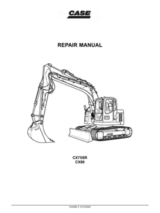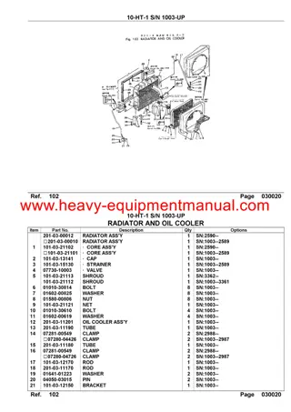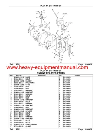
CASE CX80 Tier 3 Crawler Excavator Operator Manual Instant Download
Please open the website below to get the complete manualnn// n
Download Presentation

Please find below an Image/Link to download the presentation.
The content on the website is provided AS IS for your information and personal use only. It may not be sold, licensed, or shared on other websites without obtaining consent from the author. Download presentation by click this link. If you encounter any issues during the download, it is possible that the publisher has removed the file from their server.
E N D
Presentation Transcript
CX75SR CX75SR-LR CX80 CX135SR Tier 3 Crawler excavators Operator's Manual Print No. Lep 84336178 4th edition English 06/2010 - Original instructions Replaces Lep 84173693
THIS SAFETY ALERT SYMBOL INDICATES IMPORTANT SAFETY MESSAGES IN THIS MANUAL. WHEN YOU SEE THIS SYMBOL, CAREFULLY READ THE MESSAGE THAT FOLLOWS AND BE ALERT TO THE POSSIBILITY OF PERSONAL INJURY OR DEATH. The words Danger, Warning or Caution used on the safety decals have the following significance: DANGER: Indicates an immediate hazardous situation that, if not avoided, could result in serious injury or even death. The colour associated with Danger is RED. WARNING: Indicates a potentially hazardous situation that, if not avoided, could result in serious injury. The colour associated with Warning is ORANGE. CAUTION: Indicates a potentially hazardous situation that, if not avoided, may result in minor injury. It may also be used to alert against unsafe practices. The colour associated with Caution is YELLOW. Certain decals, in conformity with the ISO standard are in several parts. They must be interpreted as follows: The upper panel indicates the nature of the danger. The lower panel indicates appropriate avoidance of the danger. Background colour is YELLOW. Prohibition symbols such as if used, are RED. WARNING IMPROPER OPERATION OF THIS MACHINE CAN CAUSE INJURY OR DEATH. BEFORE USING THIS MACHINE, MAKE CERTAIN THAT EVERY OPERATOR: Is instructed in safe and proper use of the machine. Reads and understands the Manual(s) pertaining to the machine. Reads and understands ALL Safety Decals on the machine. Clears the area of other persons. Learns and practises safe use of machine controls in a safe, clear area before operating this machine on a job site. It is your responsibility to observe pertinent laws and regulations and follow CASE instructions on machine operation and maintenance. CNH France S.A. Company reserves the right to make changes in the specification and design of the machine without prior notice and without incurring any obligation to modify units previously sold. The description of the models shown in this manual has been made in accordance with the technical specifications known as of the date of design of this document. All data given in this manual is subject to production variations. Dimensions and weights are provided with approximate values and the machine fitting shown in the illustrations may not correspond with standard models. For precise information on specific machine models and versions, please consult your CASE Dealer. Reproduction or translation, even partial, is prohibited without written authorization from CNH France S.A. Company Lep 84336178 EN Copyright 2010 CNH France S.A. Issued March 2008 (Revised June 2010)
OPERATOR'S MANUAL CX75SR CX75SR-LR CX80 CX135SR Tier 3
https://www.ebooklibonline.com Hello dear friend! Thank you very much for reading. Enter the link into your browser. The full manual is available for immediate download. https://www.ebooklibonline.com
QUICK REFERENCE SECTION GUIDE Shown are the Sections contained within this book. 1 - To the owner 2 - Identification numbers/Machine components 3 - Safety/Decals/Hand signals 4 - Controls/Instruments/Accessories 5 - Operating instructions 6 - Servicing intervals 7 - Lubrication/Filters/Fluids 8 - Maintenance/Adjustments 9 - Electrical system 10 - Storage 11 - Specifications 12 - Alphabetical index
TABLE OF CONTENTS SECTION 1 - TO THE OWNER .................................................................................................................. 1-1 Hydraulic crawler excavators CX75SR, CX75SR-LR, CX80 and CX135SR ............................................1-1 Official documents ....................................................................................................................................1-3 Right, left, front and rear of the machine ..................................................................................................1-3 SECTION 2 - IDENTIFICATION NUMBERS/MACHINE COMPONENTS .................................................. 2-1 Type, serial number and year of manufacture of the machine .................................................................2-1 Description of the main components ........................................................................................................2-4 SECTION 3 - SAFETY/DECALS/HAND SIGNALS .................................................................................... 3-1 Safety instructions ....................................................................................................................................3-1 Before using the machine ........................................................................................................................3-2 Operating the machine .............................................................................................................................3-3 Preventing risks caused by vibrations ......................................................................................................3-4 Cab protection (F.O.P.S.) .........................................................................................................................3-5 Quick coupler (except CX75SR-LR) ........................................................................................................3-5 Safety area ...............................................................................................................................................3-5 Using an implement other than a bucket (except CX75SR-LR) ...............................................................3-5 Implement operation and maintenance (except CX75SR-LR) .................................................................3-5 Parking the machine ................................................................................................................................3-6 Maintenance and adjustments .................................................................................................................3-6 Preventing fires or explosions ..................................................................................................................3-7 Prevention of burns ..................................................................................................................................3-8 Decals ......................................................................................................................................................3-9 Hand signals ..........................................................................................................................................3-26 SECTION 4 - CONTROLS/INSTRUMENTS/ACCESSORIES .................................................................... 4-1 Cab door ..................................................................................................................................................4-1 Steps and access handles .......................................................................................................................4-2 Position of the operator s compartment controls and accessories ...........................................................4-4 RH control arm .........................................................................................................................................4-5 Instrument panel ......................................................................................................................................4-6 LH control arm (CX75SR, CX75SR-LR, CX80) ........................................................................................4-8 LH control arm (CX135SR) ....................................................................................................................4-10 Working light switch ...............................................................................................................................4-12 Windshield washer switch ......................................................................................................................4-12 Windshield wiper switch .........................................................................................................................4-12 High speed travel switch ........................................................................................................................4-13 Heating and ventilation control ...............................................................................................................4-14 Heating, ventilation or air-conditioning control .......................................................................................4-15 Quick coupler locking and unlocking control switch (except CX75SR-LR) ............................................4-16 Control locking lever ...............................................................................................................................4-17 Dipper and upperstructure swing LH control lever .................................................................................4-18 Boom and bucket RH control lever ........................................................................................................4-18
TABLE OF CONTENTS Controls/Instruments/Accessories (continued) Travel control levers and pedals .............................................................................................................4-19 Backhoe-offset boom control pedal (CX75SR, CX135SR) .....................................................................4-19 Articulated boom adjustment pedal (CX135SR) .....................................................................................4-19 Equipment offset pivot control pedal (CX80) ..........................................................................................4-19 Option pedal ...........................................................................................................................................4-20 Unlocking and locking of pedals .............................................................................................................4-20 Dozer blade control lever ........................................................................................................................4-21 Cab light .................................................................................................................................................4-21 Coat hanger hook ...................................................................................................................................4-21 Rear RH side window .............................................................................................................................4-22 Glove compartment ................................................................................................................................4-22 Storage tray ............................................................................................................................................4-22 Ashtray ...................................................................................................................................................4-23 Sun shield ...............................................................................................................................................4-23 Fuse box .................................................................................................................................................4-23 Cab radio compartment ..........................................................................................................................4-24 Speaker compartments ..........................................................................................................................4-24 Operator's seat .......................................................................................................................................4-25 Windshield ..............................................................................................................................................4-29 Lower front window .................................................................................................................................4-31 Window-breaker hammer .......................................................................................................................4-32 Air vents ..................................................................................................................................................4-32 Rear view mirrors ...................................................................................................................................4-33 Upper hood (CX75SR, CX75SR-LR, CX80) ...........................................................................................4-35 Fuel tank .................................................................................................................................................4-36 Engine hood ...........................................................................................................................................4-37 Side doors ..............................................................................................................................................4-39 Rotary light cable ....................................................................................................................................4-42 Towing hole ............................................................................................................................................4-43 Cab protection (F.O.P.S.) .......................................................................................................................4-43 Load handling eyes (except CX75SR-LR) ..............................................................................................4-44 Windshield washer reservoir ..................................................................................................................4-45 Lower panels ..........................................................................................................................................4-45 Safety valves ..........................................................................................................................................4-46 Optional tool supply valves .....................................................................................................................4-46 Optional tool flow selector valve (except CX75SR-LR) ..........................................................................4-47 Fuel tank filler pump (CX75SR, CX75SR-LR, CX80) .............................................................................4-48 Fuel tank filler pump (CX135SR) ............................................................................................................4-51 SECTION 5 - OPERATING INSTRUCTIONS ............................................................................................. 5-1 Before using the machine .........................................................................................................................5-1 Operating the machine .............................................................................................................................5-2
TABLE OF CONTENTS Operating instructions (continued) Run-in period ............................................................................................................................................5-3 Starting the engine ...................................................................................................................................5-4 Bringing the machine up to operating temperature ..................................................................................5-6 Engine operation ......................................................................................................................................5-7 Stopping the engine .................................................................................................................................5-8 Operating the machine in cold weather ....................................................................................................5-9 Operating the machine in hot weather .....................................................................................................5-9 Machine operation ..................................................................................................................................5-10 Machine travel ........................................................................................................................................5-12 Setting the 2.10 m or 2.85 m dipper into the transport position (CX135SR) ..........................................5-15 Removal and installation of heavy equipment items ..............................................................................5-16 Transporting the machine ......................................................................................................................5-17 Handling the machine ............................................................................................................................5-23 Operating the machine in water .............................................................................................................5-24 Operating the machine on sloping ground .............................................................................................5-24 Parking the machine ..............................................................................................................................5-25 Towing ....................................................................................................................................................5-27 Operating the backhoe bucket ...............................................................................................................5-28 Load handling .........................................................................................................................................5-29 Lowering the attachment in the event of a machine failure ....................................................................5-32 Quick coupler installation (except CX75SR-LR) .....................................................................................5-33 Quick tool installation and removal (except CX75SR-LR) ......................................................................5-33 Auxiliary hydraulic circuits (except CX75SR-LR) ...................................................................................5-38 SECTION 6 - SERVICING INTERVALS ..................................................................................................... 6-1 Servicing instructions ...............................................................................................................................6-1 Hourmeter ................................................................................................................................................6-2 Daily inspections ......................................................................................................................................6-2 Quick coupler servicing instructions (except CX75SR-LR) ......................................................................6-4 Quick coupler incorrect functioning (except CX75SR-LR) .......................................................................6-4 Intervals (CX75SR, CX75SR-LR) ............................................................................................................6-5 Intervals (CX80) .......................................................................................................................................6-8 Intervals (CX135SR) ..............................................................................................................................6-11 SECTION 7 - LUBRICATION/FILTERS/FLUIDS ........................................................................................ 7-1 Fluids and Lubricants ...............................................................................................................................7-1 Environment .............................................................................................................................................7-4 Fluid and lubricant capacities and specifications .....................................................................................7-4 Grease points ...........................................................................................................................................7-6 Levels .....................................................................................................................................................7-32 Engine (CX75SR, CX75SR-LR, CX80) ..................................................................................................7-36 Engine (CX135SR) .................................................................................................................................7-39
TABLE OF CONTENTS Lubrication/Filters/Fluids (continued) Cooling system (CX75SR, CX75SR-LR, CX80) .....................................................................................7-42 Cooling system (CX135SR) ....................................................................................................................7-46 Fuel system (CX75SR, CX75SR-LR, CX80) ..........................................................................................7-50 Fuel system (CX135SR) .........................................................................................................................7-54 Filling the fuel tank ..................................................................................................................................7-59 Releasing pressure in the hydraulic system ...........................................................................................7-60 Hydraulic system (CX75SR, CX75SR-LR, CX80) ..................................................................................7-62 Hydraulic system (CX135SR) .................................................................................................................7-68 Bleeding air from the hydraulic components ..........................................................................................7-75 Replacing the filters and hydraulic fluid when a hydraulic breaker is used (CX75SR, CX80) ................7-77 Replacing the filters and hydraulic fluid when a hydraulic breaker is used (CX135SR) .........................7-79 Air filter ...................................................................................................................................................7-80 Swing reduction gear (CX135SR) ..........................................................................................................7-85 Travel reduction gears ............................................................................................................................7-87 SECTION 8 - MAINTENANCE/ADJUSTMENTS ........................................................................................ 8-1 Tracks .......................................................................................................................................................8-1 Checking the condition of rubber tracks ...................................................................................................8-6 Replacing the rubber tracks ......................................................................................................................8-6 Track rollers and idler wheels ...................................................................................................................8-9 Radiator and oil cooler ............................................................................................................................8-10 Fan and alternator drive belt ...................................................................................................................8-11 Adjustment of engine valve rocker clearances .......................................................................................8-13 Fuel tank filter .........................................................................................................................................8-13 Inspecting and cleaning the machine .....................................................................................................8-14 Checking the machine settings ...............................................................................................................8-14 Checking for cylinder leakage ................................................................................................................8-14 Tooth tip wear limits on the backhoe bucket ..........................................................................................8-15 Replacing a tooth tip on a backhoe bucket .............................................................................................8-16 Replacing a backhoe bucket ..................................................................................................................8-17 Cab protection (F.O.P.S.) .......................................................................................................................8-18 Fire extinguisher .....................................................................................................................................8-19 Welding on the machine .........................................................................................................................8-19 Checking the quick coupler latching hook opening (except CX75SR-LR) ..............................................8-20 Air conditioning .......................................................................................................................................8-23 Plastic and resin parts ............................................................................................................................8-26 Engine troubleshooting ...........................................................................................................................8-27 Hardware torque inspection ....................................................................................................................8-29
TABLE OF CONTENTS SECTION 9 - ELECTRICAL SYSTEM ........................................................................................................ 9-1 Fuses .......................................................................................................................................................9-1 Batteries ...................................................................................................................................................9-4 Alternator ..................................................................................................................................................9-8 Starter motor ............................................................................................................................................9-9 Replacing a bulb ......................................................................................................................................9-9 Adjusting the working lights ....................................................................................................................9-11 SECTION 10 - STORAGE ......................................................................................................................... 10-1 Storing the machine ...............................................................................................................................10-1 SECTION 11 - SPECIFICATIONS ............................................................................................................ 11-1 Engine ....................................................................................................................................................11-1 Hydraulic system ....................................................................................................................................11-2 Undercarriage ........................................................................................................................................11-4 Safety devices ........................................................................................................................................11-5 Operator's compartment .........................................................................................................................11-5 Noise levels ............................................................................................................................................11-5 Vibration level inside the cab .................................................................................................................11-5 Cab .........................................................................................................................................................11-6 Weights ..................................................................................................................................................11-6 Booms ....................................................................................................................................................11-7 Dippers ...................................................................................................................................................11-7 Backhoe buckets ....................................................................................................................................11-8 Machine overall dimensions (CX75SR) ................................................................................................11-10 Machine overall dimensions (CX75SR-LR) ..........................................................................................11-12 Machine overall dimensions (CX80) ....................................................................................................11-13 Machine overall dimensions (CX135SR) ..............................................................................................11-14 Working range (CX75SR) ....................................................................................................................11-17 Working range (CX75SR-LR) ...............................................................................................................11-19 Working range (CX80) .........................................................................................................................11-20 Working range (CX135SR) ..................................................................................................................11-21 Quick coupler (except CX75SR-LR) ....................................................................................................11-24 SECTION 12 - ALPHABETICAL INDEX .................................................................................................. 12-1
TABLE OF CONTENTS NOTES
SECTION 1 4 TO THE OWNER HYDRAULIC CRAWLER EXCAVATORS CX75SR, CX75SR-LR, CX80 and CX135SR CT02C001 1 Type presented: CX135SR Dealer's Stamp CNH France S.A. 16-18 rue des Rochettes 91150 MORIGNY - CHAMPIGNY FRANCE 1-1
SECTION 1 - TO THE OWNER Your machine has been designed and built to the high- est standards of quality. It conforms to all current safety regulations. See "Official documents". However, the risk of accidents can never be completely excluded. That is why it is essential to observe ele- mentary safety rules and precautions. The engine and fuel system on your machine is designed and built to government emissions stand- ards. Tampering by dealers, customers, operators and users is strictly prohibited by law. Failure to comply could result in government fines, rework charges, invalid warranty, legal action and possible confiscation of the machine until rework to original condition is completed. Engine service and/or repairs must be done by a certified technician only! Read this manual carefully, paying particular attention to the instructions concerning safety, operation and maintenance so as to avoid the risk of injury while operating or servicing the machine. Before permitting a new operator on this machine, make sure: The standard attachments and tools of this machine are designed to carry out all kinds of earthmoving and rehandling operations. If you want to use this machine to handle a load (pipes, culverts, formwork, etc.), make sure that it is designed to carry out this kind of work. For this type of application, the machine must be equipped with safety valves, an overload indicator, a load handling chart corresponding to the type of machine and its attachment and a load fixing point. All legal requirements must also be strictly observed. 1. That the operator is qualified to operate the machine correctly and safely. 2. That the operator has read and understood the instructions given in this manual. Always keep this manual in the operator's compart- ment (in the seat back, behind the operator's seat). Make sure it is always complete and in good condition. If you wish to obtain extra copies, or copies in lan- guages other than that of the country of use, consult your CASE Dealer. Do not use this machine for any application or purpose other than those described in this manual. If the machine is to be used for work involving the use of special attachments, accessories or equipment, con- sult your CASE Dealer in order to make sure that any adaptations or modifications made are in keeping with the machine's technical specifications and with prevail- ing safety requirements. Your CASE Dealer is at your disposal for any further information. He will also provide any after-sales serv- ice you may require, and genuine CASE spare parts, your guarantee of quality and match. Any modification or adaptation which is not approved by the manufacturer may invalidate the machine's ini- tial conformity with safety requirements. The machine must undergo regular inspections, the frequency of which varies according to the type of use. Consult your CASE Dealer. 1-2
SECTION 1 - TO THE OWNER OFFICIAL DOCUMENTS A certificate defining the weight shown on the manufacturer's plate: - Indication that the weight shown on the manufacturer s plate is a value using the heaviest configuration and that it does not always correspond to the transport configuration. A "EC" declaration of conformity: - For a new construction equipment machine, series produced to a type approved design, designed and manufactured in accordance with the requirements of European directive 98/37/EC, concerning machine safety and mainly: 1 - The following directives: - 89/336/EC: Electromagnetic compatibility - 2000/14/EC: Noise level (outside the cab) - 2006/42/EC: Noise level (inside the cab) 2 - The following European standards: - EN 474-1: Safety - General requirements - EN 474-5: Safety - Hydraulic excavators including load handling IMPORTANT: An original of this "EC" declaration is supplied with each machine and must be kept carefully by the owner. IMPORTANT: The official documents supplied with the machine must be kept by the owner so as to be able to present them to any inspecting authority which may request them. RIGHT, LEFT, FRONT AND REAR OF THE MACHINE The terms "Right", "Left", "Front" and "Rear" are used in this manual to indicate the sides as they are seen from the operator's seat when the cab is over the idler wheels. A The illustration opposite shows the machine in nor- mal TRAVEL position. In normal TRAVEL position, the cab is over the idler wheels. The travel reduction gears are at the rear of the upperstructure. A. B. C. D. E. F. FRONT REAR RH SIDE LH SIDE TRAVEL MOTORS IDLER WHEELS F F D C E E B CT02D269 2 1-3
SECTION 1 - TO THE OWNER NOTES 1-4
SECTION 2 4 IDENTIFICATION NUMBERS/MACHINE COMPONENTS TYPE, SERIAL NUMBER AND YEAR OF MANUFACTURE OF THE MACHINE When ordering parts, obtaining information or assistance, always supply your CASE Dealer with the type and serial number of your machine or accessories. Write the following in the spaces below: the type, serial number and year of manufacture of your machine, accessories and the serial numbers of the various hydraulic and mechanical components. MACHINE CT02C036 1 (1) Type.......................................................................... (2) Serial number........................................................... (3) Year of build.............................................................. 1 2 3 CT04A171B 2 2-1
SECTION 2 - IDENTIFICATION NUMBERS/MACHINE COMPONENTS ENGINE (CX75SR, CX75SR-LR, CX80) Make and type ................................ ISUZU AU-4LE2X ........................................................................................ Serial number................................................................. ........................................................................................ CT02C062 3 (CX135SR) Make and type ................................. ISUZU AJ-4JJ1X ........................................................................................ Serial number................................................................. ........................................................................................ CT02C050 4 2-2
SECTION 2 - IDENTIFICATION NUMBERS/MACHINE COMPONENTS COMPONENT SERIAL NUMBERS Hydraulic pump.............................................................. ........................................................................................ Swing reduction gear..................................................... ........................................................................................ Travel reduction gears ................................................... ........................................................................................ Travel control valve ........................................................ ........................................................................................ Attachment control valve............................................... ........................................................................................ Swing control valve........................................................ ........................................................................................ CAB PROTECTION (F.O.P.S.) (optional) Complies with ISO 10262 level 2 standard. Identification number .................................................... ........................................................................................ CD09C001 5 QUICK COUPLER (except CX75SR-LR) (optional) 5 2 4 1 (1) Serial number .......................................................... (2) Weight....................................................................... (3) Operating pressure.................................................. (4) Type.......................................................................... (5) Part number.............................................................. (6) Date of manufacture................................................. (7) Safe working load..................................................... 6 3 7 CS97A032C 6 2-3
SECTION 2 - IDENTIFICATION NUMBERS/MACHINE COMPONENTS DESCRIPTION OF THE MAIN COMPONENTS The CX75SR, CX75SR-LR, CX80 and CX135SR are fully hydraulic excavators. They consist of an undercarriage fitted with tracks and a turntable bearing which supports the upperstructure frame. The upperstructure frame sup- ports the attachment, at the front end of the machine, plus the engine, hydraulics and cab. When the operator works the controls, the engine-driven pump delivers hydraulic fluid to the control valves. The control valves distrib- ute the hydraulic fluid to the various cylinders and motors concerned. A cooling system maintains the hydraulic fluid at normal operating temperature. 9 24 23 6 11 5 7 1 12 20 19 8 5 13 2 14 10 3 4 22 15 18 17 16 21 CT02C001A 7 1. Cab/Operator's compartment 2. Upperstructure 3. Undercarriage 4. Steps 5. Access handles 6. Boom 7. Boom cylinders 8. Dipper 9. Dipper cylinder 10. Backhoe bucket 11. Backhoe bucket cylinder 12. Engine compartment 13. Counterweight 14. Upper rollers 15. Lower rollers 16. Travel reduction gears 17. Idler wheels 18. Tracks 19. Hydraulic reservoir 20. Fuel tank 21. Dozer blade (if equipped) 22. Dozer blade cylinders (if equipped) 23. Attachment positioning pivot (CX80) 24. Pivot cylinder (CX80) 2-4
SECTION 3 30 SAFETY/DECALS/HAND SIGNALS SAFETY INSTRUCTIONS Your safety and that of people around you depends on you. It is essential that you understand this manual for the correct operation, inspection, lubrication and main- tenance of this machine. Read this manual carefully and check that: - You understand fully the symbols on the controls and the safety signs used in this manual and on the machine. - You understand fully the speed, stability, braking and steering characteristics of the machine. If you are in any doubt, consult your CASE Dealer. The safety messages in this manual concern situations which may arise during normal machine operation and servicing. These safety messages also indicate the dif- ferent ways of coping with these situations. Other safety messages are used throughout the manual to indicate specific dangers. Whatever type of work is being done (earthmoving, handling, etc.), the safety measures for private or pub- lic work-sites are those which conform to current regu- lations in the country concerned, or the type of operation concerned (example: mining, quarrying, underground work). The safety instructions given in this manual are a sum- mary of the basic rules to be respected at all times and do not exempt you from insurance requirements or from abiding by the highway code. Always keep this manual in the location provided for that purpose (behind the operator s seat). Make sure it is always complete and in good condition. If you wish to obtain extra copies, or copies in languages other than that of the country of use, consult your CASE Dealer. CT02C003 1 3-1
SECTION 3 - SAFETY/DECALS/HAND SIGNALS BEFORE USING THE MACHINE 12. Check that no tools or other items have been left on the machine (be it on the undercarriage or the upperstructure) or in the operator's compartment. 1. Avoid loose fitting clothing, loose or uncovered long hair, jewellery or any other items which could get caught up in machinery. 13. The operator must be alone on the machine at all times. Do not allow anyone to stand on or around the machine. 2. Different types of job will require different types of protective equipment. Items such as hard hats, safety shoes, heavy gloves, reflector type jackets, respirators, ear protection and eye protection may be required. Before starting a job, determine what protective equipment will be necessary. Use this equipment at all times. 14. To get in or out of the cab, it is imperative that the upperstructure frame is in line with the undercar- riage. 15. When alighting from or getting into the operator's compartment, always face the machine and use the steps and access handles. 3. Do not attempt to operate this machine unless you have first read and perfectly understood the safety messages and instructions appearing in this manual. 16. Be sure you know the position and function of each control. Incorrect operation of the controls can cause serious injuries. 4. Operating the machine requires full attention and care on the part of the operator can avoid acci- dents. Get to know the machine's possibilities and limitations and the working space required. There are areas of poor visibility in the working range of the machine. Have someone guide you for all areas where visibility is not perfect. 17. Check all controls and safety devices in a safe, open area before starting work. 18. Keep away from dangerous areas such as ditches, overhangs, rocky areas, etc. Make a sur- vey of the work-site and determine the possible dangers before using the machine. 19. Before parking the machine, make sure that the ground is stable. Plan the worksite so that the ground is flat, hard and level. 5. Grease, oil, mud or (in winter) ice on the steps and access handles can cause accidents. Make sure they are kept clean at all times. 20. Before moving the machine to work in a new area, walk around to determine all possible causes of accidents there. Holes, obstacles, debris and other danger risks in the working area can cause serious injury. 6. Every day, inspect the machine to detect any signs of hydraulic fluid leakage. Tighten the con- nections or replace any defective components as necessary. 7. Remove any obstructions which hinder visibility. Keep the windshield, rear view mirror and win- dows clean at all times. 21. Be ready to meet emergencies. Always carry a first aid kit and if possible, fire extinguisher (not supplied) within easy reach on board. Make sure the fire extinguisher is regularly serviced in con- formance with the manufacturer's instructions. 8. Make sure the windshield wiper works correctly. 9. Make sure you are perfectly familiar with hand sig- nals in daily use on the worksite so as to be able to obtain help with tight manoeuvres or when car- rying out operations where visibility is poor. 22. Check the fastening of the main components: counterweight, turntable bearing and operator's compartment. In the event of problems, consult your CASE Dealer. 10. Before undertaking any travel or working opera- tions during hours of darkness, make sure the lighting and signalling equipment is fully operative. 23. Make sure you understand the symbols used on the machine safety decals. Keep the decals clean so that they are perfectly legible at all times. 11. Before any travel operation, make sure that the doors and hoods are properly latched. 3-2
SECTION 3 - SAFETY/DECALS/HAND SIGNALS 24. Work out a means of convenient escape from the machine (emergency exit via the windshield or the rear window glass) in the event of the machine turning over or tipping over or the cab door being jammed. 5. Before starting the engine, check the direction of travel (in forward drive, the reduction gears should be to the rear of the machine). 6. Do not work near overhead high-voltage electric lines without checking beforehand that all neces- sary measures have been taken to respect the minimum distances: Less than 57 000 volts: 3 metres. More than 57 000 volts: 5 metres. 25. Make sure you are perfectly familiar with traffic regulations and special safety equipment require- ments before transporting this machine on a pub- lic highway. 26. When loading trucks, never swing the load over the truck cab. 7. Study the position of any existing pipelines or con- duits before starting work. Electrical cables, gas and water pipes and other underground installa- tions can cause serious injury. 27. Before undertaking any travel on the job site, make sure the itinerary to be followed is com- pletely safe. If bridges are to be crossed, make sure they are perfectly capable of supporting the weight of the machine. 8. Always make allowance for working conditions (sloping or rough ground), the site and weather conditions when driving the machine. 28. Always steer round large obstacles such as boul- ders, big trees, etc. 9. Do not allow anyone to stand in the machine working area. Accidental operation of the upper- structure swing control or of an attachment control could cause an accident. Stop all operations until everyone has moved away. QUICK COUPLER (except CX75SR-LR) (optional) 1. It is mandatory for the switch to be in the locked position when operating the machine. 10. Before operating the dozer blade (if equipped) or pivoting the backhoe-offset boom (if equipped), make sure that there is no one in the working area of the latter. 2. Every day, check that the locking bar functions correctly and that it is not fouled by foreign matter. Clean the locking system if necessary. 3. If you are obliged to use the quick coupler with buckets not manufactured by CASE, make sure the diameter of the pins and the width between the bucket lugs meet the dimensions needed to fit the quick coupler (pins, washers, bushings, etc.). Consult your CASE Dealer. 11. Operate all controls gradually to ensure smooth machine operation. 12. Whenever load handling operations are to be car- ried out, it is imperative to adhere strictly to the instructions given in this manual and local legisla- tion. OPERATING THE MACHINE 13. It is forbidden to use the machine to carry out tasks other than those for which it is intended. Never use the equipment for sweeping the ground to level out rubble or push objects (transversal stress on the attachment). 1. When working on a public highway, use standard traffic signs and take into consideration the work- ing range of the upperstructure and its attach- ments. Local or national regulations stipulate the number, type and location of reflector strips. 14. Stop the engine and remove the starter switch key when the machine is not in use, even for short periods of time. 2. Avoid running the engine in a confined space. If there is no alternative, proper ventilation must be provided at all times. 15. In some configurations, the working range of the attachment allows the tool to interfere with the machine. Always maintain a safe minimum dis- tance between the tool and the machine (swaying of the tool or incorrect operation). 3. Do not allow anyone else on the machine. The passenger could fall or cause an accident. 4. Never operate the working or travel controls unless you are properly seated in the operator s seat with the seat belt correctly fastened. 3-3
SECTION 3 - SAFETY/DECALS/HAND SIGNALS PREVENTING RISKS CAUSED BY VIBRATIONS 16. To access or exit the operator s compartment, the LH control arm must be in the raised position. Never forget this basic requirement. The machine's vibration affects the comfort and in some cases the health and safety of the operator. To reduce vibration risks to a minimum: 17. Never leave the operator's compartment while the engine is running. 18. To get in or out of the cab, it is imperative that the upperstructure frame is in line with the undercar- riage. 1. Make sure that the machine, the equipment and the tool are suitable for the work to be carried out. 2. Make sure that the machine is in good condition and that servicing intervals are complied with. 19. Dust, smoke or mist can reduce visibility and cause an accident. Reduce speed or come to a complete halt until visibility has improved. 3. Check the track tension adjustment and the play in equipment linkages. 20. Never jump down from the machine. When alight- ing from the machine or the upperstructure, always face the machine and use the steps and access handles. 4. Make sure that the operator's seat and is adjust- ment controls are in good condition and then adjust the seat to suit the operator's size and weight. The operator s seat complies with the ISO 7096, 2000 standard, EM 6 class. 21. In the event of an operating problem or failure, move the machine to a safe place, lower the attachment to the ground, shut down the engine and remove the starter switch key. Locate the problem, report it if necessary and take the nec- essary steps to warn others not to attempt to operate the machine. During work: 1. Operate all controls gradually to ensure smooth machine operation. 2. Modify the machine's operation to suit the working conditions. 22. Before tilting the operator's seat back forward, raise the armrests to prevent them from fouling with the control levers. 3. During travel, adjust the machine's speed, reduc- ing it if necessary. 4. Make sure that the machine's operating radius is in good condition, and free of obstacles and holes. 23. (CX135SR) If the machine is equipped with the 2.10 or 2.85 m dipper, for any work with the machine, the hooking point on the head of the dip- per cylinder must be in the work position. 24. (CX135SR) If the machine is equipped with the 2.10 m or 2.85 m dipper, the dipper cylinder top attachment point must be in the transport position before transporting the machine. 3-4
SECTION 3 - SAFETY/DECALS/HAND SIGNALS CAB PROTECTION (F.O.P.S.) (optional) QUICK COUPLER (except CX75SR-LR) (optional) 1. Never try to weld or straighten up the protective structure (F.O.P.S.). 1. Never place the control switch in the unlocked position when the machine is working. 2. Do not modify the protective structure (F.O.P.S.) in any way. Any modification, such as welding, drill- ing, cutting, addition of accessories, as well as damage suffered following an impact reduces the protection that it provides. Replace the protective structure (F.O.P .S.) if it has suffered an impact and do not attempt to repair it. 2. Each time a bucket is installed on the quick cou- pler, close the bucket and raise the attachment so as to be able to make a visual check that the bucket pin is correctly engaged in the latching hook. 3. The quick coupler modifies the working range of the machine. In certain attachment positions the tool may foul the machine. Always leave a safety distance. 3. Incorrect inspection or service work of the protec- tive structure (F.O.P.S.) may lead to serious injury. Carry out inspection operations of the protective structure (F.O.P.S.) given in this manual. If the pro- tective structure (F.O.P.S.) or its components need to be replaced, use only those parts that are listed in the spare parts catalogue corresponding to your machine. 4. Never carry out load handling using the front or rear anchoring points used to install the tool on the quick coupler. 5. Never put your hands inside the quick coupler and never attempt to adjust or repair the quick coupler if the engine is running. SAFETY AREA The safety area is the space necessary for the machine to operate at the maximum range of the tool and at full swing (360 ) plus 2 metres. 2 1. Working area. 2. Safety area. 1 CS97M019 2 USING AN IMPLEMENT OTHER THAN A BUCKET (except CX75SR-LR) (optional) When using a special implement (hydraulic breaker, cutter crusher etc.), refer to the operator's manual pro- vided with the implement. IMPLEMENT OPERATION AND MAINTENANCE (except CX75SR-LR) For the implement operation and maintenance, refer to the operator's manual provided with the implement. 3-5
SECTION 3 - SAFETY/DECALS/HAND SIGNALS PARKING THE MACHINE 7. If the attachment is raised or if the machine moves without an operator, serious injury can result. Before carrying out maintenance on this machine, proceed as follows: When parking the machine, proceed as follows: 1. Position the machine on flat, level ground, away from soft ground, excavations or poorly shored cavities. 1. Park the machine on flat, level ground. 2. Lower the attachment until it is resting on the ground. 2. Place the upperstructure and the attachment in line with the undercarriage, retract the attach- ment and dig the bucket into the ground. 3. Lower the dozer blade (if equipped) until it rests on the ground. 3. Lower the dozer blade (if equipped) until it rests on the ground. 4. Stop the engine and remove the starter switch key. 4. Stop the engine and remove the starter switch key. 5. Lock the tracks to prevent any machine move- ment. 5. It is imperative to lift the LH control arm before leaving the operator s compartment. 8. Any unauthorized modifications made to this machine can cause serious injury. Do not under- take any modifications without first consulting your CASE Dealer. Any modifications made must be in conformity with the technical specifications of the machine and any current safety legislation requirements. 6. Lock the cab door. 7. Make sure that the hoods and doors are prop- erly latched. 8. Check that no part of the machine is encroach- ing on the highway. If this cannot be avoided, install the necessary regulation signalling equipment. 9. Certain components of the machine are subject to type approval. When replacing such components, it is mandatory to make sure that they conform to regulations. For safety's sake, use genuine CASE parts. MAINTENANCE AND ADJUSTMENTS 1. Do not try to service this machine unless you have first read and perfectly understood the safety messages and instructions featuring in this man- ual. 10. Pressurized hydraulic fluid or grease which pene- trates the skin can cause serious injury. Take the necessary safety precautions (safety clothing and protection for face and hands) to avoid such risks. Also, before using these products, read the manu- facturer's instructions concerning their use. If hydraulic fluid penetrates the skin, call a doctor immediately. 2. When carrying out service work always wear suit- able dress. Avoid loose-fitting clothing. 3. Release pressure completely in the hydraulic sys- tem before disconnecting the hydraulic piping. Hydraulic oil escaping under pressure can cause serious injury. 11. Coolant solution is toxic. Avoid contact with skin, eyes and clothing. Antidote: EXTERNAL: rinse thoroughly with water and remove soiled clothes. INTERNAL: do not induce vomiting. Rinse the mouth out with water. Seek medical advice. EYES: rinse thoroughly with water and seek med- ical advice. 4. Before commencing any work on the machine, place a "Do not operate" tag on the right-hand control arm. 5. Always wear eye protection when using a tool that might project metal particles. Use a hammer with a soft face, such as copper, for installing pins. 6. Badly carried out maintenance or adjustments can cause serious injuries. If you do not under- stand a servicing or adjustment procedure, con- sult your CASE Dealer. 3-6
SECTION 3 - SAFETY/DECALS/HAND SIGNALS QUICK COUPLER (except CX75SR-LR) (optional) 12. The pressure in the track tension cylinders is high. Follow the procedure described in this manual carefully for increasing or reducing track tension. 1. Every day, check that the locking bar functions correctly and that it is not fouled by foreign matter. Clean the locking system if necessary. 13. When carrying out a welding operation on the undercarriage or upperstructure carriage as authorized by the manufacturer and in accord- ance with his instructions, disconnect the batter- ies, disconnect the alternator B+ and D+ terminal wires and connect the welding apparatus earth cable to the component on which the welding operation is to be performed. Never connect the welding apparatus to the undercarriage when welding on the upperstructure (or vice-versa). Never connect the welding apparatus earth to a component of the hydraulic system. PREVENTING FIRES OR EXPLOSIONS 1. Engine fuel can cause an explosion or a fire. - Never refuel when the engine is running. - Never smoke while refuelling. - Take all necessary safety measures when welding, grinding or working near a naked flame. 2. Always use a non-inflammable solvent for clean- ing parts. 3. A spark or a naked light can cause the hydrogen in a battery to explode. To avoid all risk of explo- sion, be sure to follow the instructions below: - When disconnecting battery cables, always disconnect the negative cable (-) first. - When connecting battery cables, always con- nect the negative cable (-) last. - Never short-circuit the battery terminals with metal objects. - Do not weld, grind or smoke near the batteries. 14. When using compressed air, take the necessary precautions to protect your face. 15. Clean the machine regularly. Accumulations of grease, dirt and debris can cause injuries or dam- age the machine. 16. Periodically inspect the fastening of the main components, as part of the machine maintenance programme: counterweight, turntable bearing and operator's compartment. In the event of problems, consult your CASE Dealer. 4. Always store batteries in a safe place, out of the reach of children. 17. If the accumulator is not functioning correctly, see your CASE Dealer. Never try to carry out any servicing operation on the accumulator. If this instruction is not followed serious injury can result. 5. Sparks can fly from the electrical system or the engine exhaust. Before running the machine in an area where there may be inflammable gasses, make sure there is adequate ventilation. 18. The accumulator is charged with nitrogen under high pressure. Do not weld or allow flames to come near to the accumulator. 6. If possible, make sure there is a fire extinguisher (not supplied) within easy reach on board the machine. Make sure the fire extinguisher is regu- larly serviced in conformity with the manufac- turer's instructions. 19. There is high pressure fuel in the feed pipe when the engine is running and immediately after it has been shut down. Wait for 2 minutes after engine shut down before you do any maintenance or inspections to allow the pressure to drop in the pipe. 7. Clean the machine regularly, removing all debris and inflammable material. 8. Make sure there are no leaks and replace any damaged hoses, lines or connectors. After any repair work, clean the machine before operating. 20. High-voltage is charged to the controller and/or to the injector while the engine is running and immediately after it has been shut down. Do not touch the controller or the injector. If it is necessary to touch them for maintenance purposes, consult your CASE Dealer. 3-7
Suggest: If the above button click is invalid. Please download this document first, and then click the above link to download the complete manual. Thank you so much for reading
SECTION 3 - SAFETY/DECALS/HAND SIGNALS PREVENTION OF BURNS 1. The electrolyte in the batteries can cause serious burns. Batteries contain sulphuric acid. Avoid con- tact with skin, eyes and clothing. Antidote: EXTERNAL: rinse thoroughly with water and remove soiled clothes. INTERNAL: do not induce vomiting. Rinse the mouth out with water. Seek medical advice. EYES: rinse thoroughly with water for 15 min- utes and seek medical advice. 2. When the batteries electrolyte freezes, they can explode if you try to charge them or start up the engine with booster batteries. To prevent the elec- trolyte from freezing, always keep the batteries fully charged. 3. Batteries give off explosive gases. Keep all naked flames, sparks and cigarettes away. Ensure ade- quate ventilation when charging batteries or when using in a confined place. Always protect your eyes when working near the batteries. 4. Boiling coolant solution can spray out if the radia- tor cap is removed while the system is still hot. Before removing the cap, let the system cool down and then turn the cap to its first notch, wait- ing until all pressure is released. Then remove the cap. 5. Never touch battery terminals with the hands as electrolysis can take place within the human body and damage vital organs. 3-8
https://www.ebooklibonline.com Hello dear friend! Thank you very much for reading. Enter the link into your browser. The full manual is available for immediate download. https://www.ebooklibonline.com


