CASE CX350C TIER 4 CRAWLER EXCAVATOR Service Repair Manual Instant Download
Please open the website below to get the complete manualnn// n
Download Presentation

Please find below an Image/Link to download the presentation.
The content on the website is provided AS IS for your information and personal use only. It may not be sold, licensed, or shared on other websites without obtaining consent from the author. Download presentation by click this link. If you encounter any issues during the download, it is possible that the publisher has removed the file from their server.
E N D
Presentation Transcript
CX350C Tier 4 Crawler Excavator SERVICE MANUAL Part number 84402832 1st edition English Printed in U.S.A. Copyright 2011 CNH America LLC. All Rights Reserved. Case is a registered trademark of CNH America LLC. Racine Wisconsin 53404 U.S.A. August 2011
Section 1001 Safety, general information and standard torque data 84402832 NA - May 2011
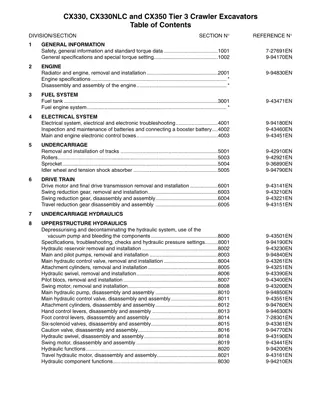
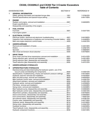
CONTENTS GENERAL INFORMATION. . . . . . . . . . . . . . . . . . . . . . . . . . . . . . . . . . . . . . . . . . . . . . . . . . . . . . . . . . . . . . . . . . . . . . . . . . . 3 Safety. . . . . . . . . . . . . . . . . . . . . . . . . . . . . . . . . . . . . . . . . . . . . . . . . . . . . . . . . . . . . . . . . . . . . . . . . . . . . . . . . . . . . . . . . . . . . 4 ROPS Judgment Method . . . . . . . . . . . . . . . . . . . . . . . . . . . . . . . . . . . . . . . . . . . . . . . . . . . . . . . . . . . . . . . . . . . . . . . . . . . . 6 Standard Torque Data For Cap Screws And Nuts . . . . . . . . . . . . . . . . . . . . . . . . . . . . . . . . . . . . . . . . . . . . . . . . . . . . . . 10 84402832 NA - May 2011 1001-1 Copyright 2011 CNH FRANCE S.A. PRINTED IN FRANCE
https://www.ebooklibonline.com Hello dear friend! Thank you very much for reading. Enter the link into your browser. The full manual is available for immediate download. https://www.ebooklibonline.com
Safety, general information and standard torque data GENERAL INFORMATION CLEANING Clean all metal parts except bearings, in a suitable cleaning solvent or by steam cleaning. Do not use caustic soda for steam cleaning. After cleaning, dry and put oil on all parts. Clean oil passages with compressed air. Clean bearings in a suitable cleaning solvent, dry the bearings completely and put oil on the bearings. INSPECTION Check all parts when the parts are disassembled. Replace all parts that have wear or damage. Small scoring or grooves can be removed with a hone or crocus cloth. Complete a visual inspection for indications of wear, pitting and the replacement of parts necessary to prevent early failures. BEARINGS Check bearings for easy action. If bearings have a loose fit or rough action replace the bearing. Wash bearings with a suitable cleaning solvent and permit to air dry. DO NOT DRY BEARINGS WITH COMPRESSED AIR. NEEDLE BEARINGS Before you press needle bearings in a bore always remove any metal protrusions in the bore or edge of the bore. Before you press bearings into position put petroleum jelly on the inside and outside diameter of the bearings. GEARS Check all gears for wear and damage. Replace gears that have wear or damage. Oil seals, O-rings and gaskets. Always install new oil seals, O-rings and gaskets. Put petroleum jelly on seals and O-rings. SHAFTS Check all shafts that have wear or damage. Check the bearing and oil seal surfaces of the shafts for damage. SERVICE PARTS Always install genuine Case service parts. When ordering refer to the Parts Catalogue for the correct part number of the genuine Case replacement items. Failures due to the use of other than genuine Case replacement parts are not covered by warranty. LUBRICATION Only use the oils and lubricants specified in the Operator s or Service Manuals. Failures due to the use of non-specified oils and lubricants are not covered by warranty. 84402832 NA - May 2011 1001-3
Safety, general information and standard torque data Safety This symbol means ATTENTION! BECOME ALERT! YOUR SAFETY IS INVOLVED. The message that follows the symbol contains important information about safety. Carefully read the message. Make sure you fully understand the causes of possible injury or death. To prevent injury always follow the Warning, Caution and Danger notes in this section and throughout the manual. Put the warning tag shown below on the key for the key switch when servicing or repairing the machine. One warning tag is supplied with each machine. Additional tags are available from your service parts supplier. WARNING Read the operator's manual to familiarize yourself with the correct control functions. WARNING Operate the machine and equipment controls from the seat position only. Any other method could result in serious injury. WARNING This is a one man machine, no riders allowed. WARNING Before starting engine, study Operator s Manual safety messages. Read all safety signs on machine. Clear the area of other persons. Learn and practice safe use of controls before operating. It is your responsibility to understand and follow manufacturers instructions on machine operation, ser- vice and to observe pertinent laws and regulations. Operator's and Service Manuals may be obtained from your CASE dealer. WARNING If you wear clothing that is too loose or do not use the correct safety equipment for your job, you can be injured. Always wear clothing that will not catch on objects. Extra safety equipment that can be required includes hard hat, safety shoes, ear protection, eye or face protection, heavy gloves and reflector clothing. WARNING When working in the area of the fan belt with the engine running, avoid loose clothing if possible, and use extreme caution. WARNING When doing checks and tests on the equipment hydraulics, follow the procedures as they are written. DO NOT change the procedure. WARNING When putting the hydraulic cylinders on this machine through the necessary cycles to check operation or to remove air from a circuit, make sure all people are out of the way. WARNING Use insulated gloves or mittens when working with hot parts. 84402832 NA - May 2011 1001-4
Safety, general information and standard torque data WARNING Lower all attachments to the ground or use stands to safely support the attachments before you do any maintenance or service. WARNING Pin sized and smaller streams of hydraulic oil under pressure can penetrate the skin and result in serious infection. If hydraulic oil under pressure does penetrate the skin, seek medical treatment immediately. Maintain all hoses and tubes in good condition. Make sure all connections are tight. Make a replacement of any tube or hose that is damaged or thought to be damaged. DO NOT use your hand to check for leaks, use a piece of cardboard or wood. WARNING When removing hardened pins such as a pivot pin, or a hardened shaft, use a soft head (brass or bronze) hammer or use a driver made from brass or bronze and a steel head hammer. WARNING When using a hammer to remove and install pivot pins or separate parts using compressed air or using a grinder, wear eye protection that completely encloses the eyes (approved goggles or other approved eye protectors). WARNING Use suitable floor (service) jacks or chain hoist to raise wheels or tracks off the floor. Always block machine in place with suitable safety stands. WARNING When servicing or repairing the machine, keep the shop floor and operator's compartment and steps free of oil, water, grease, tools, etc. Use an oil absorbing material and/or shop cloths as required. Use safe practices at all times. WARNING Some components of this machine are very heavy. Use suitable lifting equipment or additional help as instructed in this Service Manual. WARNING Engine exhaust fumes can cause death. If it is necessary to start the engine in a closed place, remove the exhaust fumes from the area with an exhaust pipe extension. Open the doors and get outside air into the area. WARNING When the battery electrolyte is frozen, the battery can explode if (1), you try to charge the battery, or (2), you try to jump start and run the engine. To prevent the battery electrolyte from freezing, try to keep the battery at full charge. If you do not follow these instructions, you or others in the area can be injured. 84402832 NA - May 2011 1001-5
Safety, general information and standard torque data ROPS Judgment Method 1. Purpose Check against the ROPS judgment criteria to judge whether the machine satisfies the ROPS criteria or not. The weight and boom of the machine greatly effects whether the ROPS judgment criteria is satisfied or not. The ROPS test assumes that the weight being used is the weight of the machine when the maximum number of selectable options are mounted (as of 2009). However, depending on the derivative machinery or the order details, the weight and boom position may differ from the assumed weight or position. Criteria for judging whether a machine satisfies the ROPS criteria 2. 1) Weight The weight must not be over the weight shown below for each class. If the weight is exceeded, there is a danger that the cab could be damaged and the operator could die or sustain a serious injury when the machine falls over. If the weight exceeds the stipulated weight, the machine will not satisfy the ROPS criteria. Weight (C series model) To satisfy the ROPS criteria, the weight must not be over the indicated weight. (The below weights are the weights indicated on the nameplate within the ROPS cab) Machine weight body total Class CX250C CX250CLR CX300C CX370C CX470C 31000 kg or less 40000 kg or less 50000 kg or less * The ROPS test assumes that the CX470C has a cage guard (alone). Weight (B series model) To satisfy the ROPS criteria, the weight must not be over the indicated weight. (The below weights are the weights indicated on the nameplate within the ROPS cab) Machine weight body total Class CX130B CX160B CX180B CX210B CX230B 25000 kg or less 84402832 NA - May 2011 1001-6
Safety, general information and standard torque data 2) Boom position WARNING If the machine has been modified so that the boom position has been lowered, the machine will not satisfy the ROPS criteria. It is necessary to consult with our company if it is possible that the boom's position has been lowered by modification. The extent to which a boom position has moved cannot be determined in the same way for all machines. a Ground point With the tip of the bucket in contact with the ground surface at maximum work radius, if the position (* in the diagram) that overlaps with the cab when viewed from the side is markedly lower than that of a standard machine (standard arm), the machine will not satisfy the ROPS criteria. Also, with a machine body with a cab mounted that can withstand up to 31 tons, the effect of mounting a 24 ton machine, which is near the restriction weight, and a 21 ton machine to the same cab will not be the same. 84402832 NA - May 2011 1001-7
Safety, general information and standard torque data 3. Prohibited items Modifications that reduce the strength of a platform that has a cab with a ROPS mounted to it. (Actions or modifications that reduce the functionality of the anchoring part at the left-rear of the cab) Modifications that effect the strength of the ROPS of a cab. A modifications (red part) Allow under spec- ified conditions (gray part) forbidden all All modifications (grinding, welding, drilling holes, removing, etc.) are prohib- ited. Removal of parts is prohibited. Bar welding and making holes (up to diameter 20 mm) by drilling are possible. [C series Cab] 84402832 NA - May 2011 1001-8
Safety, general information and standard torque data [B series Cab] In general, high cabs do not satisfy the ROPS criteria. (It is necessary to consult with our company to check if the high cab model satisfies the ROPS criteria.) 84402832 NA - May 2011 1001-9
Safety, general information and standard torque data Standard Torque Data For Cap Screws And Nuts BOLT AND NUT TIGHTENING Tighten alternating between left and right and top and bottom so that uniform tightening force is applied. If Loctite was used on a removed bolt (there is something white sticking to the bolt when it is removed), clean the old Loctite off with cleaning fluid, dry the bolt, then apply 2 - 3 drops of Loctite to the thread section of the bolt. Torque table Bolt nominal diameter (size) M6 10 M8 13 M10 17 M12 19 M14 22 M16 24 M18 27 M20 30 Wrench Tightening torque Wrench Tightening torque [mm] [N m] Hexagon bolt 6.9 19.6 39.2 58.8 98.1 156.9 196.1 294.2 5 [mm] [N m] 6 8 10 12 14 14 17 Hexagon socket head bolt 8.8 21.6 42.1 78.5 117.7 176.5 245.2 343.2 84402832 NA - May 2011 1001-10
Section 1002A Specifications 84402832 NA - May 2011
CONTENTS Overall (CX350C). . . . . . . . . . . . . . . . . . . . . . . . . . . . . . . . . . . . . . . . . . . . . . . . . . . . . . . . . . . . . . . . . . . . . . . . . . . . . . . . . . . 3 Main Data . . . . . . . . . . . . . . . . . . . . . . . . . . . . . . . . . . . . . . . . . . . . . . . . . . . . . . . . . . . . . . . . . . . . . . . . . . . . . . . . . . . . . 3 Performance . . . . . . . . . . . . . . . . . . . . . . . . . . . . . . . . . . . . . . . . . . . . . . . . . . . . . . . . . . . . . . . . . . . . . . . . . . . . . . . . . . . 3 Main Unit Dimensions . . . . . . . . . . . . . . . . . . . . . . . . . . . . . . . . . . . . . . . . . . . . . . . . . . . . . . . . . . . . . . . . . . . . . . . . . . . 3 Engine . . . . . . . . . . . . . . . . . . . . . . . . . . . . . . . . . . . . . . . . . . . . . . . . . . . . . . . . . . . . . . . . . . . . . . . . . . . . . . . . . . . . . . . . 3 Cooling System . . . . . . . . . . . . . . . . . . . . . . . . . . . . . . . . . . . . . . . . . . . . . . . . . . . . . . . . . . . . . . . . . . . . . . . . . . . . . . . . 4 Upper Side Work System . . . . . . . . . . . . . . . . . . . . . . . . . . . . . . . . . . . . . . . . . . . . . . . . . . . . . . . . . . . . . . . . . . . . . . . . 4 Operating Device . . . . . . . . . . . . . . . . . . . . . . . . . . . . . . . . . . . . . . . . . . . . . . . . . . . . . . . . . . . . . . . . . . . . . . . . . . . . . . . 4 Swing Units . . . . . . . . . . . . . . . . . . . . . . . . . . . . . . . . . . . . . . . . . . . . . . . . . . . . . . . . . . . . . . . . . . . . . . . . . . . . . . . . . . . . 5 Travel Lower Body. . . . . . . . . . . . . . . . . . . . . . . . . . . . . . . . . . . . . . . . . . . . . . . . . . . . . . . . . . . . . . . . . . . . . . . . . . . . . . 5 Hydraulic Equipment . . . . . . . . . . . . . . . . . . . . . . . . . . . . . . . . . . . . . . . . . . . . . . . . . . . . . . . . . . . . . . . . . . . . . . . . . . . . 6 Hydraulic Device . . . . . . . . . . . . . . . . . . . . . . . . . . . . . . . . . . . . . . . . . . . . . . . . . . . . . . . . . . . . . . . . . . . . . . . . . . . . . 6 Control Valve and Cylinder. . . . . . . . . . . . . . . . . . . . . . . . . . . . . . . . . . . . . . . . . . . . . . . . . . . . . . . . . . . . . . . . . . . . . 6 Capacities, Filters. . . . . . . . . . . . . . . . . . . . . . . . . . . . . . . . . . . . . . . . . . . . . . . . . . . . . . . . . . . . . . . . . . . . . . . . . . . . . . . 6 Coolant and Oil Capacities. . . . . . . . . . . . . . . . . . . . . . . . . . . . . . . . . . . . . . . . . . . . . . . . . . . . . . . . . . . . . . . . . . . . . 6 Hydraulic Oil Filters . . . . . . . . . . . . . . . . . . . . . . . . . . . . . . . . . . . . . . . . . . . . . . . . . . . . . . . . . . . . . . . . . . . . . . . . . . . 6 Fuel Filter. . . . . . . . . . . . . . . . . . . . . . . . . . . . . . . . . . . . . . . . . . . . . . . . . . . . . . . . . . . . . . . . . . . . . . . . . . . . . . . . . . . . 6
Specifications Overall (CX350C) Main Data 34700 kg 198 kW/1900 min-1 Operating weight Engine output Performance Standard weight Swing speed 18.0 kN 9.7 min-1 Low speed 3.2 km/h High speed 5.4 km/h 264 kN 70 (35 ) 65 kPa (600 mm grouser shoe) 57 kPa (700 mm grouser shoe) 50 kPa (800 mm grouser shoe) 47 kPa (850 mm grouser shoe) 45 kPa (900 mm grouser shoe) Travel speed Maximum pulling force Grade ability Ground pressure Standard weight Swing speed 18.0 kN 9.7 min-1 Low speed 3.2 km/h High speed 5.4 km/h 264 kN 70 (35 ) 58 kPa (700 mm grouser shoe) 51 kPa (800 mm grouser shoe) 48 kPa (850 mm grouser shoe) Travel speed Maximum pulling force Grade ability Ground pressure Main Unit Dimensions Main unit length Main unit width Upper swing body width Cab width Main unit height Swing radius (rear end) Swing body rear end distance Swing body height Distance between tumblers Overall track length Overall track width Distance between tracks Track shoe width 6010 mm 3200 mm (600 G shoe) 3030 mm 1000 mm 3160 mm 3550 mm 3520 mm rear section bottom 1210 mm (not including lug height of 36 mm) 4040 mm 4980 mm 3200 mm (600 G shoe) 2600 mm 600 mm (options 700 mm, 800 mm, 850 mm, 900 mm) 480 mm (to bottom of lower frame) (not including lug height of 36 mm) Minimum ground clearance Engine Isuzu 6HK1X diesel engine 4-cycle, water-cooled, overhead camshaft type Common rail system (electronic control), cooled EGR, with tur- bocharger (variable displacement type), DPD system Name Model Number of cylinders - bore x stroke 6 - D115 mm x 125 mm 84402832 NA - May 2011 1002A-3
Specifications Total stroke volume Maximum torque Starter Charging generator Battery 7.790 L 1043 N m/1500 min-1 24 V 5.0 kW reduction type 24 V 50 A AC type 12 V 128 Ah/5 HR x 2 Cooling System Fan type Radiator Fin type Fin pitch Oil cooler Fin type Fin pitch Intercooler Fin type Fin pitch Fuel cooler Fin type Fin pitch D850 mm, 6 blades, suction Wavy 1.75 mm Wavy 1.75 mm Wavy 2.5 mm Wavy 2.0 mm Upper Side Work System Model Components, dimensions, working di- mensions Bucket capacity (reference) Bucket width Bucket width with side cutter Bucket weight with side cutter Boom length Backhoe Attachment Heaped 1.40 m3(Leveled 1.04 m3) 1300 mm 1440 mm 1150 kg 6450 mm Standard (STD/HD) (3.25 m) 3250 mm 4040 mm 1680 mm 173 11170 mm 11900 mm Long (4.04 m) Ultra-short (2.21 m) Short (2.63 m) Arm type Arm length Bucket radius Bucket wrist angle Maximum digging radius Maximum digging radius at ground line Maximum digging depth Maximum vertical straight wall dig- ging depth Maximum digging height Maximum dump height Minimum swing radius at front Height for minimum swing radius at front 2630 mm 2210 mm 10670 mm 10200 mm 10980 mm 11720 mm 10470 mm 9990 mm 7340 mm 8140 mm 6730 mm 6300 mm 6350 mm 7150 mm 5970 mm 5080 mm 10370 mm 7230 mm 4500 mm 10670 mm 7540 mm 4560 mm 10320 mm 7140 mm 4630 mm 9850 mm 6770 mm 4660 mm 8480 mm 8490 mm 8540 mm 8650 mm Operating Device Operator's seat Position Left side Adjustable forward and back and up and down, reclining mech- anism, with seat suspension Sealed steel type, all reinforced glass, ROPS, with sunroof Structure Cab Levers and pedals For travel use Lever and pedal type (hydraulic pilot type) x 2 84402832 NA - May 2011 1002A-4
Specifications For operating machine use Instruments and switches Work mode switchover Travel mode switchover One-touch idle Engine emergency stop Monitor device Machine status display (TFT color liquid crystal) Message display Work mode select status Instruments Fuel gauge Enginecoolanttemperaturegauge Hydraulic oil temperature gauge Hour meter Rear view camera monitor Warning display and warning alarm * has warning alarm Overheat (*) Battery charge (*) Electrical system abnormality (*) Refill fuel (*) Engine oil pressure (*) Refill coolant (*) Engine pre-heat Auto Warm-up Air cleaner (*) Anti-theft device triggered Engine system abnormality (*) Engine emergency stop (*) Illumination equipment Right front tool box front sur- face: Cab top: 24 V 70 W x 2 Boom side: 24 V 70 W x 1 Interior light 4 V 10 W x 1 Horn Electric horn x 2 Wiper with intermittent function, window washer, air conditioner, 4 rear view mirrors (2 on cab sides, 1 front right stay, 1 CTWT rear right), 1 rear view mirror (on CTWT) Lever type (hydraulic pilot type) x 2 3 modes (SP/H/A) Low-speed/high-speed switch type Knob switch type Switch type SP/H/A Working light 24 V 70 W x 1 Other Swing Units Swing circle Swing hydraulic motor Reduction gear Swing parking brake Swing bearing type (with inner gear) Fixed displacement piston motor x 1 Planetary gear 2-stage reduction gear Mechanical lock (operational lever linkage type) Travel Lower Body Travel hydraulic motor Reduction gear Travel brake Parking brake Track shoe Model Number of shoes (per side) 48 Shoe width Grouser height Link pitch Roller No. of upper rollers (per side) No. of lower rollers (per side) Track belt tension adjuster Variable displacement piston motor x 2 Planetary gear 2-stage reduction gear(Nabtesco Corporation) Hydraulic lock Mechanical lock (travel lever linkage type) Assembly-type triple grouser shoe 600 mm (options 700 mm, 800 mm, 850 mm, 900 mm) 36 mm 216 mm 2 8 Grease cylinder type (with cushion spring) 84402832 NA - May 2011 1002A-5
Specifications Hydraulic Equipment Hydraulic Device Hydraulic pump drive type Hydraulic pump Direct engine link (no transmission) Double variable displacement piston pump x 1 Gear pump x 1 Piston pump 2 x 285 L/min Gear pump 28.5 L/min Simultaneous output full-horsepower control 34.3 MPa (37.3 MPa for pressure boost) 27.4 MPa (boom down) 39.2 MPa (boom up/arm/bucket) Model Discharge volume Pump control method Set pressure of main relief valve Set pressure of overload relief valve Control Valve and Cylinder Control valve Model Operating method Cylinder Boom cylinder Arm cylinder Bucket cylinder Quadruple spool + quintuple spool x 1 Hydraulic pilot type: travel, swing, and operating machine No. of cylinders x tube bore - rod diameter - stroke 2 x D145 mm - D100 mm - 1495 mm 1 x D170 mm - D120 mm - 1748 mm 1 x D150 mm - D105 mm - 1210 mm Capacities, Filters Coolant and Oil Capacities 35.4 L 580 L 49 L 11 L 5 L 350 L 175 L Coolant Fuel Engine lubricating oil (including remote oil filter) Travel reduction gear lubricating oil (one side) Swing reduction gear lubricating oil Hydraulic oil Hydraulic oil tank regulation amount Hydraulic Oil Filters Suction filter (inside tank) Return filter (inside tank) Pilot line filter (inside pump chamber) 105 m 6 m 8 m Fuel Filter 2 m 7 m Main filter Pre-filter 84402832 NA - May 2011 1002A-6
Section 1002B Main Equipment Table 84402832 NA - May 2011
CONTENTS Main Equipment Table. . . . . . . . . . . . . . . . . . . . . . . . . . . . . . . . . . . . . . . . . . . . . . . . . . . . . . . . . . . . . . . . . . . . . . . . . . . . . . . 3 Lower Component . . . . . . . . . . . . . . . . . . . . . . . . . . . . . . . . . . . . . . . . . . . . . . . . . . . . . . . . . . . . . . . . . . . . . . . . . . . . . . . . . . 3 Travel Unit . . . . . . . . . . . . . . . . . . . . . . . . . . . . . . . . . . . . . . . . . . . . . . . . . . . . . . . . . . . . . . . . . . . . . . . . . . . . . . . . . . . . . 3 Take-up Roller. . . . . . . . . . . . . . . . . . . . . . . . . . . . . . . . . . . . . . . . . . . . . . . . . . . . . . . . . . . . . . . . . . . . . . . . . . . . . . . . . . 3 Upper Roller . . . . . . . . . . . . . . . . . . . . . . . . . . . . . . . . . . . . . . . . . . . . . . . . . . . . . . . . . . . . . . . . . . . . . . . . . . . . . . . . . . . 3 Lower Roller . . . . . . . . . . . . . . . . . . . . . . . . . . . . . . . . . . . . . . . . . . . . . . . . . . . . . . . . . . . . . . . . . . . . . . . . . . . . . . . . . . . 3 Recoil Spring. . . . . . . . . . . . . . . . . . . . . . . . . . . . . . . . . . . . . . . . . . . . . . . . . . . . . . . . . . . . . . . . . . . . . . . . . . . . . . . . . . . 3 Shoe (CX350C) . . . . . . . . . . . . . . . . . . . . . . . . . . . . . . . . . . . . . . . . . . . . . . . . . . . . . . . . . . . . . . . . . . . . . . . . . . . . . . . . 4 Upper Component . . . . . . . . . . . . . . . . . . . . . . . . . . . . . . . . . . . . . . . . . . . . . . . . . . . . . . . . . . . . . . . . . . . . . . . . . . . . . . . . . . 5 Swing Unit (CX350C) . . . . . . . . . . . . . . . . . . . . . . . . . . . . . . . . . . . . . . . . . . . . . . . . . . . . . . . . . . . . . . . . . . . . . . . . . . . 5 Engine-related . . . . . . . . . . . . . . . . . . . . . . . . . . . . . . . . . . . . . . . . . . . . . . . . . . . . . . . . . . . . . . . . . . . . . . . . . . . . . . . . . . . . . 6 Engine . . . . . . . . . . . . . . . . . . . . . . . . . . . . . . . . . . . . . . . . . . . . . . . . . . . . . . . . . . . . . . . . . . . . . . . . . . . . . . . . . . . . . . . . 6 DPD . . . . . . . . . . . . . . . . . . . . . . . . . . . . . . . . . . . . . . . . . . . . . . . . . . . . . . . . . . . . . . . . . . . . . . . . . . . . . . . . . . . . . . . . . . 6 Air Cleaner (double element) . . . . . . . . . . . . . . . . . . . . . . . . . . . . . . . . . . . . . . . . . . . . . . . . . . . . . . . . . . . . . . . . . . . . . 6 Radiator . . . . . . . . . . . . . . . . . . . . . . . . . . . . . . . . . . . . . . . . . . . . . . . . . . . . . . . . . . . . . . . . . . . . . . . . . . . . . . . . . . . . . . . 6 Hydraulic Device . . . . . . . . . . . . . . . . . . . . . . . . . . . . . . . . . . . . . . . . . . . . . . . . . . . . . . . . . . . . . . . . . . . . . . . . . . . . . . . . . . . 7 Hydraulic Pump . . . . . . . . . . . . . . . . . . . . . . . . . . . . . . . . . . . . . . . . . . . . . . . . . . . . . . . . . . . . . . . . . . . . . . . . . . . . . . . . 7 Control-related . . . . . . . . . . . . . . . . . . . . . . . . . . . . . . . . . . . . . . . . . . . . . . . . . . . . . . . . . . . . . . . . . . . . . . . . . . . . . . . . . . . . . 8 Control Valve. . . . . . . . . . . . . . . . . . . . . . . . . . . . . . . . . . . . . . . . . . . . . . . . . . . . . . . . . . . . . . . . . . . . . . . . . . . . . . . . . . . 8 Solenoid Valve (4 stack) . . . . . . . . . . . . . . . . . . . . . . . . . . . . . . . . . . . . . . . . . . . . . . . . . . . . . . . . . . . . . . . . . . . . . . . . . 8 Remote Control Valve (left/right, travel operations) . . . . . . . . . . . . . . . . . . . . . . . . . . . . . . . . . . . . . . . . . . . . . . . . . . 9 Remote Control Valve for Left/Right Operations. . . . . . . . . . . . . . . . . . . . . . . . . . . . . . . . . . . . . . . . . . . . . . . . . . . . . 9 Remote Control Valve for Travel Operations. . . . . . . . . . . . . . . . . . . . . . . . . . . . . . . . . . . . . . . . . . . . . . . . . . . . . . . . 9 Remote Control Valve Characteristic Diagram . . . . . . . . . . . . . . . . . . . . . . . . . . . . . . . . . . . . . . . . . . . . . . . . . . . . . . 9 Operation Remote Control Valve Control Diagram. . . . . . . . . . . . . . . . . . . . . . . . . . . . . . . . . . . . . . . . . . . . . . . . . . . 9 Travel Remote Control Valve Control Diagram . . . . . . . . . . . . . . . . . . . . . . . . . . . . . . . . . . . . . . . . . . . . . . . . . . . . . 10 Cushion Valve (heat circuit, with shuttle valve). . . . . . . . . . . . . . . . . . . . . . . . . . . . . . . . . . . . . . . . . . . . . . . . . . . . . 11 Center Joint. . . . . . . . . . . . . . . . . . . . . . . . . . . . . . . . . . . . . . . . . . . . . . . . . . . . . . . . . . . . . . . . . . . . . . . . . . . . . . . . . . . 11 Backhoe Attachment . . . . . . . . . . . . . . . . . . . . . . . . . . . . . . . . . . . . . . . . . . . . . . . . . . . . . . . . . . . . . . . . . . . . . . . . . . . . . . . 11 Cylinder . . . . . . . . . . . . . . . . . . . . . . . . . . . . . . . . . . . . . . . . . . . . . . . . . . . . . . . . . . . . . . . . . . . . . . . . . . . . . . . . . . . . . . 11
84402832 NA - May 2011 1002B-2 Copyright 2011 CNH FRANCE S.A. PRINTED IN FRANCE
Main Equipment Table Main Equipment Table Lower Component Travel Unit Manufacturer Motor type Nabtesco Corporation Variable displacement piston motor Automatic 2-speed switchover with parking brake 290.7/170.1 cm3/rev 34.3 MPa 285 L/min 47.39 kN m min. (including reduction gear) 35.8 - 37.8 MPa Intake amount Operating pressure Operating flow Brake torque Relief valve set pressure Automatic 2-speed switchover pressure Reduction gear Reduction gear type Reduction ratio Dry weight 26.5 MPa Planetary gear 2-stage reduction gear 40.467 399 kg Take-up Roller LH5146 164.6 kg Sumitomo part No. Weight Upper Roller Weight 43 kg Lower Roller Weight 61 kg Recoil Spring Item Yoke Sems B M16 x 50 Threaded rod Groove height N M64 SP pin 10 x 100 Recoil spring Grease cylinder assembly Sems B M16 x 65 Assembly (Total) Mounting length of spring Weight (kg) 39.8 0.5 49.1 1.9 0.1 119.4 41.1 0.3 252.2 779 mm Q'ty 1 4 1 1 1 1 1 2 84402832 NA - May 2011 1002B-3
Main Equipment Table Shoe (CX350C) Weight or Q'ty 2217 kg 1 set 48 192 192 2473 kg 1 set 48 192 192 2618 kg 1 set 48 192 192 2735 kg 1 set 48 192 192 2817 kg 1 set 48 192 192 600 grouser Link Shoe Bolt Nut 700 grouser Link Shoe Bolt Nut 800 grouser Link Shoe Bolt Nut 850 grouser Link Shoe Bolt Nut 900 grouser Link Shoe Bolt Nut 84402832 NA - May 2011 1002B-4
Main Equipment Table Upper Component Swing Unit (CX350C) Swing motor assembly Swing motor Manufacturer Motor type Kawasaki Precision Machinery Ltd. Fixed displacement piston motor With parking brake 180.1 cm3/rev 30.4 MPa 285 L/min 1010.8 N m min. 3.1 MPa max. 30.4 MPa Intake amount Operating pressure Operating flow Mechanical brake torque Brake off pressure Relief valve set pressure Swing reduction gear Reduction gear type Reduction ratio Dry weight Turntable bearing No. of teeth Weight Counterweight Weight Planetary gear 2-stage reduction gear 27.143 437 kg 92 540 kg 6400 kg 84402832 NA - May 2011 1002B-5
Main Equipment Table Engine-related Engine Sumitomo part No. Engine model name KSH11600 Isuzu 6HK1X diesel engine 4-cycle, water-cooled, overhead camshaft type, common rail system (electronic control), cooled EGR, with turbocharger (variable displace- ment type), DPD system No. of cylinders - bore - stroke 6 - D115 mm - 125 mm Total displacement 7.79 L Compression ratio 17.5 Rated output 198 kW/1900 min-1 Maximum torque 1043 N m/about 1500 min-1 Fuel consumption ratio 221 - 241 g/kW h at 1900 min-1 Engine dry weight About 640 kg Engine dimension L 1388 - W 1047 - H 1194 mm Cooling fan D850 mm - suction type - 6 vanes, plastic and steel With bell mouth-type fan guide Pulley ratio 0.9 (reduction) Charging generator 24 V 50 A AC type Starter motor 24 V 5 kW reduction type Coolant capacity 14.5 L Oil pan capacity Max: 46 L Min: 36 L (not including oil filter) Direction of rotation Right (viewed from fan side) Compliant with JISD 0006-2000. Engine type DPD Isuzu Motors, Ltd. 38 kg Manufacturer Weight Air Cleaner (double element) Nippon Donaldson, Ltd. Manufacturer Element (outer) Element (inner) Weight 13 kg Radiator Tokyo Radiator MFG. Co.,Ltd. 39.0 kg 12.9 L 11.9 kg 9.4 L 12.6 kg - 1.0 kg x 2 0.3 L x 2 159 kg Manufacturer Oil cooler Weight Oil volume Weight Coolant capacity Weight Capacity Weight Capacity Radiator Air cooler Fuel cooler Total weight 84402832 NA - May 2011 1002B-6
Main Equipment Table Hydraulic Device Hydraulic Pump Kawasaki Precision Machinery Ltd. Manufacturer Main pump Pump type Displacement capacity Operating pressure Double variable displacement piston pump 150 x 2 cm3/rev 34.3 MPa 37.3 MPa 1900 min-1 289 x 2 L/min (at Pd = 3.0 MPa. 1900 min-1) 285 x 2 L/min (at Pd = 8.0 MPa. 1900 min-1) Rated Maximum Input revolution speed Maximum discharge flow Pilot pump Pump type Displacement capacity Operating pressure Maximum discharge flow Control method Gear pump 15 cm3/rev 3.9 MPa 28.5 L/min (at 1900 min-1) Hydraulic simultaneous constant output control Maximum flow adjustment control through external com- mands (negative control) Maximum flow adjustment control through external com- mand milli-amp (negative control, front side) Setting horsepower adjustment control through external command milli-amp 188 kg Dry weight 84402832 NA - May 2011 1002B-7
Main Equipment Table Control-related Control Valve STD (with 2nd option add-on valve) Manufacturer Maximum flow Overload set pressure KYB Corporation 285 L/min (at 1900 min-1) 27.4 MPa boom down 39.2 MPa boom up, arm, bucket 22.6 MPa attachment 2 34.3 MPa 37.3 MPa 2.55 MPa Straight travel circuit Boom-up/arm 2 pumps internal flow Boom and arm load holding circuit Boom-down regenerative circuit Bucket-close regenerative circuit Arm-in forced regenerative circuit Swing priority variable orifice 2 pumps flow (external flow merging) 199 kg Main relief set pressure (at boosting) Foot relief set pressure Function Weight 215 kg Solenoid Valve (4 stack) Yuken Kogyo Co., Ltd. Manufacturer Valve specifications Maximum flow Rated pressure Port size P B 20 L/min Other 5 L/min 4.5 MPa P.T.B. port C1, C2, C3, C4, C5 ports G3/8 G1/4 Solenoid specifications Operating voltage Power consumption Weight DC 20 - 32 V 17 W max. 5 kg 84402832 NA - May 2011 1002B-8
Main Equipment Table Remote Control Valve (left/right, travel operations) Remote Control Valve for Left/Right Operations Kawasaki Precision Machinery Ltd. 3.92 MPa 0.64 - 2.45 MPa primary short type 19 25 1.9 kg Manufacturer Operating pressure Secondary pressure Operating 1, 3 port 2, 4 port Weight Remote Control Valve for Travel Operations Kawasaki Precision Machinery Ltd. 3.92 MPa 0.64 - 2.45 MPa primary short type 12.4 5.5 kg Manufacturer Operating pressure Secondary pressure Operating angle Weight Remote Control Valve Characteristic Diagram Operation Remote Control Valve Control Diagram Ports 1, 3 Secondary pressure [MPa] Push rod stroke [mm] Operating angle [deg.] Secondary pressure 1 84402832 NA - May 2011 1002B-9
Main Equipment Table Ports 2, 4 Secondary pressure [MPa] Push rod stroke [mm] Operating angle [deg.] Secondary pressure 1 Travel Remote Control Valve Control Diagram Secondary pressure [MPa] Push rod stroke [mm] Pedal operating angle [deg.] Secondary pressure 1 84402832 NA - May 2011 1002B-10
Main Equipment Table Cushion Valve (heat circuit, with shuttle valve) Yanagisawa Seiki MFG. Co., Ltd. G 3/8 (A - P ports) G 1/4 (Q - V ports) 12.5 kg Manufacturer Port size Weight Center Joint Operating pressure High-pressure passage (ABCD) Drain port (T) Pilot port (P) High-pressure passage (ABCD) Drain port (T) Pilot port (P) Forward right Forward left Backward right Backward left Drain port Pilot port 55.5 kg 34.3 MPa 1.0 MPa 3.9 MPa 360 L/min 40 L/min 31 L/min G1 G1 G1 G1 G1/2 G1/4 Flow Port A Port B Port C Port D Port T Port P Weight Backhoe Attachment Cylinder Boom Cylinder Cylinder bore Rod diameter Maximum retracted length Stroke Weight D145 mm D100 mm 2090 mm 1495 mm 279 kg Arm Cylinder Cylinder bore Rod diameter Maximum retracted length Stroke Weight D170 mm D120 mm 2445 mm 1748 mm 462 kg Bucket cylinder Cylinder bore Rod diameter Maximum retracted length Stroke Weight D150 mm D105 mm 1870 mm 1210 mm 276 kg 84402832 NA - May 2011 1002B-11
Main Equipment Table 84402832 NA - May 2011 1002B-12
Section 1002C Main Unit Weight 84402832 NA - May 2011
CONTENTS Main Unit Weight . . . . . . . . . . . . . . . . . . . . . . . . . . . . . . . . . . . . . . . . . . . . . . . . . . . . . . . . . . . . . . . . . . . . . . . . . . . . . . . . . . . 3 Divided Weight (standard specifications) CX350C. . . . . . . . . . . . . . . . . . . . . . . . . . . . . . . . . . . . . . . . . . . . . . . . . . . . . . . 3 Stand Alone Part Weight (CX350C) . . . . . . . . . . . . . . . . . . . . . . . . . . . . . . . . . . . . . . . . . . . . . . . . . . . . . . . . . . . . . . . . . . . 4 Shoe Weight (per side) CX350C . . . . . . . . . . . . . . . . . . . . . . . . . . . . . . . . . . . . . . . . . . . . . . . . . . . . . . . . . . . . . . . . . . . . . . 4 Arm Weight (CX350C). . . . . . . . . . . . . . . . . . . . . . . . . . . . . . . . . . . . . . . . . . . . . . . . . . . . . . . . . . . . . . . . . . . . . . . . . . . . . . . 4
Suggest: If the above button click is invalid. Please download this document first, and then click the above link to download the complete manual. Thank you so much for reading
Main Unit Weight Main Unit Weight Divided Weight (standard specifications) CX350C Weight (kg) 34700 Code Component name A Operating weight Upper component (including counterweight and turntable bearing) Counterweight Lower component (with grouser shoe) Main unit weight Attachments Boom (including cylinders) Arm (including cylinders and linkage) B 15370 6420 12290 27700 7000 3920 1800 C D E F G H 84402832 NA - May 2011 1002C-3
https://www.ebooklibonline.com Hello dear friend! Thank you very much for reading. Enter the link into your browser. The full manual is available for immediate download. https://www.ebooklibonline.com


