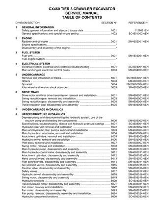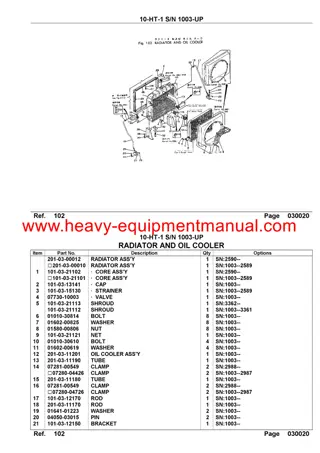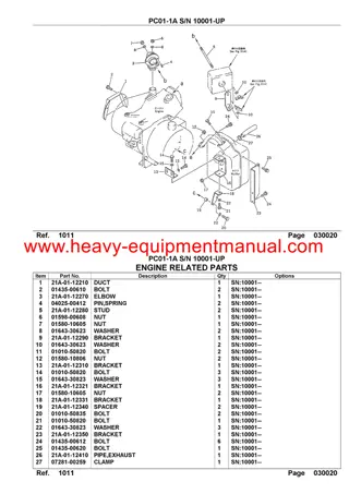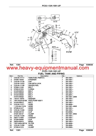
CASE CX210C TIER 4 CRAWLER EXCAVATOR Service Repair Manual Instant Download
Please open the website below to get the complete manualnn//
Download Presentation

Please find below an Image/Link to download the presentation.
The content on the website is provided AS IS for your information and personal use only. It may not be sold, licensed, or shared on other websites without obtaining consent from the author. Download presentation by click this link. If you encounter any issues during the download, it is possible that the publisher has removed the file from their server.
E N D
Presentation Transcript
Section 1004 FLUIDS AND LUBRICANTS 84402826 - May 2011
CONTENTS HYDRAULIC FLUID. . . . . . . . . . . . . . . . . . . . . . . . . . . . . . . . . . . . . . . . . . . . . . . . . . . . . . . . . . . . . . . . . . . . . . . . . . . . . . . . . 3 ENGINE OIL . . . . . . . . . . . . . . . . . . . . . . . . . . . . . . . . . . . . . . . . . . . . . . . . . . . . . . . . . . . . . . . . . . . . . . . . . . . . . . . . . . . . . . . 3 FUEL . . . . . . . . . . . . . . . . . . . . . . . . . . . . . . . . . . . . . . . . . . . . . . . . . . . . . . . . . . . . . . . . . . . . . . . . . . . . . . . . . . . . . . . . . . . . . 4 Conditions applicable to diesel fuel. . . . . . . . . . . . . . . . . . . . . . . . . . . . . . . . . . . . . . . . . . . . . . . . . . . . . . . . . . . . . . . . . . . . 4 RECOMMENDED CONDITIONS THAT CAN BE APPLIED TO DIESEL FUEL . . . . . . . . . . . . . . . . . . . . . . . . . . . . . . 4 84402826 - May 2011 1004-1 Copyright 2011 CNH FRANCE S.A. PRINTED IN FRANCE
FLUIDS AND LUBRICANTS Lubricants must have the correct properties for each application. IMPORTANT: The conditions of use for individual fluids and lubricants must be respected. HYDRAULIC FLUID CASE/AKCELA hydraulic fluid is specially designed for high pressure applications and for the CASE hydraulic system. The type of fluid to be used depends on the ambient temperature. ENGINE OIL The "CASE Tutela LE ENGINE OIL" is recommended for your engine. This oil ensures correct lubrication of your engine in all working conditions. If the "CASE Tutela LE ENGINE OIL" cannot be obtained, use the oil corresponding to one of the following cate- gories: API CJ-4. ACEA E6. 84402826 - May 2011 1004-3
https://www.ebooklibonline.com Hello dear friend! Thank you very much for reading. Enter the link into your browser. The full manual is available for immediate download. https://www.ebooklibonline.com
FLUIDS AND LUBRICANTS FUEL IMPORTANT: EPA regulation ultra low sulfur fuel only. The fuel must conform to Interim Tier 4/Stage 3B Ex- haust Gas Control Regulations. Use grade number 2-D (S15) fuel. Using other types of fuel may lead to stalled engine out- put or deterioration in fuel economy. During cold weather (lower than -7 ), it is temporarily acceptable to use a mixture of No. 1-D (S15) and No. 2-D (S15). Consult the fuel supplier or the CASE dealer. If the temperature drops below the fuel cloud point, out- put deficiency or engine start problems may occur due to wax crystals. Conditions applicable to diesel fuel IMPORTANT: If a serious problem occurs when other fuels are used, the warranty is invalidated. Using a non-recommended fuel may lead to damage of the fuel injection pump, injector, DPD, and other fuel supply systems or to the engine. CASEassumesnoresponsibilityforthesedamages. Note that the warranty will not be applied for these dam- ages. It is recommended that the following safety information be considered in order to prevent damage to the engine fuel supply system. The diesel fuel used must: - Some fuel suppliers mix old engine oil and diesel fuel. - be free from dust particles, even minute ones, - have the proper viscosity, - have a high cetane number, - present great fluidity at low temperatures, - have low sulphur content, - have very little residual carbon. RECOMMENDED CONDITIONS THAT CAN BE APPLIED TO DIESEL FUEL Makers of larger engine permit the use of this kind of fuel. However, do not use diesel fuel contaminated with en- gine oil in customer's engines. Not only will this fuel damage the engine, it may also have a negative impact on the exhaust gas purification function. Before using diesel fuel, confirm with the supplier whether the fuel complies with the above specifications. IMPORTANT: Consult the supplier or the CASE dealer regarding ap- propriate use of fuel additives. Do not use fuel oil or gasoline as these may damage the engine. - JIS (Japanese Industrial Standards): No. 2 - DIN (Deutsche Industrie Normen): DIN 51601 - SAE-J-313C: SAE (Society of Automotive Engineers) based on No. 2-D (S15) - BS(BritishStandards)basedonBS/2869-1970: Class A-1 - EN 590 (less than 10 ppm sulfur) - Or fuel specified by the country using these standards and this machine IMPORTANT: In order to prevent condensation during cold weather, fill the fuel tank to full after the completing the day's work. 84402826 - May 2011 1004-4
Section 1005 Conversion Table 84402826 - May 2011
CONTENTS Metric to U.S . . . . . . . . . . . . . . . . . . . . . . . . . . . . . . . . . . . . . . . . . . . . . . . . . . . . . . . . . . . . . . . . . . . . . . . . . . . . . . . . . . . . . . . 3 U.S to Metric . . . . . . . . . . . . . . . . . . . . . . . . . . . . . . . . . . . . . . . . . . . . . . . . . . . . . . . . . . . . . . . . . . . . . . . . . . . . . . . . . . . . . . . 4 84402826 - May 2011 1005-1 Copyright 2011 CNH FRANCE S.A. PRINTED IN FRANCE
Conversion Table Metric to U.S MULTIPLY square meter hectare newton newton millimeter meter kilometer kilogram kilogram/hectare gr/kW/hr. kg/cubic meter kilowatt kilopascal bar megapascal (MPA) degree C newton meter newton meter kilometer/hr cubic centimeter cubic meter cubic meter milliliter litre litre litre litre litre/min. litre/min BY 10.763 91 2.471 05 3.596 942 2.224 809 0.039 370 3.280 840 0.621 371 2.204 622 0.000 466 0.001 644 1.685 555 1.341 02 0.145 038 14.50385 145.0385 1.8 x C +32 8.850 748 0.737 562 0.621 371 0.061 024 35.314 66 1.307 950 0.033 814 1.056 814 0.879 877 0.264 172 0.219 969 0.264 172 0.219 969 TO OBTAIN square foot acre ounce force pound force inch foot mile pound ton/acre lbs/hp/hr. lb/cubic yd. horsepower lb/sq. lb/sq. psi degree F lb/inch lb/foot miles/hr. cubic inch cubic foot cubic yd. ounce (US fluid) quart (US liquid) quart (Imperial) gallon (US liquid) gallon (Imperial) gallon/min. (US liquid) gallon/min. (Imperial) AREA: FORCE: LENGTH: MASS: MASS/AREA: MASS/ENERGY: MASS/VOLUME: POWER: inch inch PRESSURE: TEMPERATURE: TORQUE: VELOCITY: VOLUME: VOLUME/TIME: 84402826 - May 2011 1005-3
Conversion Table U.S to Metric MULTIPLY square foot acre ounce force pound force inch foot mile pound ounce ton/acre lbs/hp/hr. lb/cubic yd. horsepower lb/sq. lb/sq. lb/sq. psi degree F lb/inch lb/foot miles/hr. cubic inch cubic foot cubic yd. ounce (US fluid) quart (US liquid) quart (Imperial) gallon (US) gallon (Imperial) gallon/min. BY 0.092 903 0.404 686 0.278 014 4.448 222 25.4 0.304 8 1.609 344 0.453 592 28.35 2241 702 608.277 4 0.593 276 0.745 700 6.894 757 0.069 0.070 303 0.006 895 1.8 F - 32 0.112 985 1.355 818 1.609 344 16.387 06 0.028 317 0.764.555 29.573 53 0.946 353 1.136 523 3.785 412 4.546 092 3.785 412 TO OBTAIN square meter hectare newton newton millimeter meter kilometer kilogram gram kilogram/hectare gr/kW/hr. kg/cubic meter kilowatt kilopascal bar kg/sq. cm megapascal (Mpa) degree C newton meter newton meter kilometer/hr cubic centimeter cubic meter cubic meter milliliter litre litre litre litre litre/min. AREA: FORCE: LENGTH: MASS: MASS/AREA: MASS/ENERGY: MASS/VOLUME: POWER: inch inch inch PRESSURE: psi TEMPERATURE: TORQUE: VELOCITY: VOLUME: VOLUME/TIME: 84402826 - May 2011 1005-4
Section 1900 Abbreviations 84402826 - May 2011
CONTENTS Abbreviations . . . . . . . . . . . . . . . . . . . . . . . . . . . . . . . . . . . . . . . . . . . . . . . . . . . . . . . . . . . . . . . . . . . . . . . . . . . . . . . . . . . . . . 3 84402826 - May 2011 1900-1 Copyright 2011 CNH FRANCE S.A. PRINTED IN FRANCE
Abbreviations Abbreviations Abbreviation AC A/D ABDC AC ACC ACG ACT API ASM ATDC ATF drilled head B eye B full threaded B hexagon socket head B high-strength B reamer B B+ BAT BBDC BKT BRG BTDC C/B C/U CAL CAN CFG CHK CKP CMP CO CPU DC DI DIAG DLC DMM DPD DTC ECM ECT ECU EEPROM EGR EMI EMPS ENG EPF EVRV EXH F/B F/C F/L FLW FRT description air conditioner analog/digital after bottom dead center alternating current accessory alternating current generator actuator american petroleum industry assembly after top dead center automatic transmission fluid drilled head bolt eye bolt full threaded bolt hexagon socket head bolt high-strength bolt reamer bolt battery + terminal battery before bottom dead center bracket bearing before the top dead center circuit breaker control unit calibration a control unit communication method (control area network) config check crankshaft position camshaft position carbon monoxide central processing unit direct current direct injection type diagnosis data link connector digital multi meter diesel particulate diffuser self-diagnosis code engine control module engine coolant temperature electronic control unit electrically erasable/programmable ROM exhaust gas recirculation electromagnetic interference engine module programing system engine engine protection feature electric vacuum regulating valve exhaust feedback fuel cut fusible link fusible link wire front 84402826 - May 2011 1900-3
Abbreviations Abbreviation FT FWD GEN GND HBCV HC HO2S HR HRD IAC IAT IC ID Plate IMT INL INJ ISO ISP ITP J/C JIS KW LED LH LLC LM M/V MAF MAP Max MIL milli-amp Min MPU high-strength N NC NO NOx N-TDC PM O2S OBD OEM OPT OT P/L PCV P-I PM PTO PWM QOS QWS R/L RAM REF RH ROM description fuel temperature front generator ground hose burst check valves hydrocarbon superheat O2 sensor hour high reach idle air control intake air temperature integrated circuit ID plate (Name plate) intake manifold temperature intake injection international organization for standardization intake shutter position intake throttle position joint connector japan Industrial Standard a communication method (Keyword) light emitting diode left long life coolant lifting magnet electromagnetic valve mass air flow manifold air pressure maximum warning light (diagnostic) milli-amperage minimum micro processing unit high-strength nut normally closed normally open nitrogen oxide top dead center revolution speed particle material O2 sensor on-board diagnosis original equipment manufacturer option oil temperature pilot light pump control valve/positive crankcase ventilation proportion-integration particle material power take-off pulse width modulation wave quick on start system quick warming up system relay RAM (random access memory) reference right ROM (read only memory) 84402826 - May 2011 1900-4
Abbreviations Abbreviation RP Rr RWD flush head S phillips pan head S truss head S subassembly SAE SBF SCV SIG SLD SP pin ST STD SW TDC TEMP TP TEMP UART VB VGS Turbo high-strength W toothed W W/H W/L W/S WOT description rail pressure rear rear flush head screw phillips pan head screw truss head screw sub assembly society of atomotive engineers slow blow fuse suction control valve signal shield special pin starter/start standards switch top dead center temperature throttle position temperature universal asynchronous receiver transmitter battery voltage variable geometry system turbo high-strength washer toothed washer wire/harness warning light weld splice wide open throttle 84402826 - May 2011 1900-5
Section 2000 Removal and Installation of Engine Assembly 84402826 - May 2011
CONTENTS Removal of Engine Assembly . . . . . . . . . . . . . . . . . . . . . . . . . . . . . . . . . . . . . . . . . . . . . . . . . . . . . . . . . . . . . . . . . . . . . . . . 3 Installation of Engine Assembly. . . . . . . . . . . . . . . . . . . . . . . . . . . . . . . . . . . . . . . . . . . . . . . . . . . . . . . . . . . . . . . . . . . . . . . 9 84402826 - May 2011 2000-1 Copyright 2011 CNH FRANCE S.A. PRINTED IN FRANCE
Removal and Installation of Engine Assembly Removal of Engine Assembly WARNING 1. Remove the counterweight.(For details, see "Re- moval and Installation of Counterweight".) Remove the pump.(For details, see "Removal and Installation of Hydraulic Pump".) Use a wrench 14 mm to remove the bolts (1) and (2), and then remove the fan shroud (3). Keep away from fire. Be sure to release hydraulic pressure before beginning work. The air conditioner circuit is filled with high- pressure gas, so beware of the gas released when loosening lines. Do not use open flames and do not allow sparks near the battery. 2. 3. CAUTION Be sure to stop the engine before beginning work. Be sure to inspect the wire rope and other lifting equipment before beginning work. Do not stand or pass under the suspended load. Items to prepare Wrenches (7 mm, 8 mm, 10 mm, 12 mm, 13 mm, 14 mm, 17 mm, 36 mm) Box wrench (24 mm) Shackle (with the required lifting capacity) x 2 Wire rope (with the required breaking load) Crane (with the required lifting capacity) Marking pen Caps Plugs Waste oil can Rag Cleaning fluid Wood plank 4. Use a wrench to remove the bolts (1), and then re- move the fan guard (2). 84402826 - May 2011 2000-3
Removal and Installation of Engine Assembly 5. Use a wrench (7 mm) to loosen the hose band (1) ontheradiator, andthenremovetheupperhose(2). 8. Use a wrench (8 mm) to loosen the hose band (1) on the inter cooler, and then remove the hose (2). Use caps to cover the line and hose to prevent the entry of water, dust or dirt. 6. Use a wrench (7 mm) to loosen the hose band (1) on the radiator, and then remove the lower hose (2). Use caps to cover the radiator and hoses to pre- vent the entry of water, dust or dirt. Before removing the radiator hoses, completely drain the coolant. 9. Remove the hose bands (1) in the 3 locations. 10. Prepare a waste oil can (1). Drain the engine oil before removing the engine oil hose. 7. Use a wrench (12 mm) to loosen the line bolts (1) in 2 locations, and then remove the 2 lines (2) and (3) from the compressor. Always remove the low-pressure (suction side) line (2) first. Attach caps or plugs to the compressor and lines to prevent any entry of water, dust or dirt. 11. Use a wrench (36 mm) to remove the 2 engine oil remote hoses (1). Mark the engine and hoses so that the connectors match at the time of assembly. Attach caps or plugs to the engine and hoses to prevent any entry of water, dust or dirt. Clean the engine and hoses by spraying them with a parts cleaner to prevent scratches and pre- vent dirt from accumulating on the connectors. 3 Line (discharge side) 84402826 - May 2011 2000-4
Removal and Installation of Engine Assembly 14. Use a wrench (14 mm) to remove the 1 nut (1), and then remove the wiring (2) from the starter motor. 12. Use a wrench (17 mm) to remove the bolt (1), and then remove the negative-side battery cable (2). 15. Remove the hose band (1), and then remove the fuel hose (2). When removing the terminal and harness, secure them so that they do not interfere with the frame. Also, cover with a rubber cap to protect against sparks. Attach caps or plugs to the engine and hose to prevent any entry of water, dust or dirt. 13. Use a wrench (8 mm) to remove the 1 nut (1), and then remove the wiring (2) from the starter motor. 16. Remove the hose band (1), and then remove the fuel hose (2). Attach caps or plugs to the engine and hose to prevent any entry of water, dust or dirt. 84402826 - May 2011 2000-5
Removal and Installation of Engine Assembly 17. Use a wrench (13 mm) to remove the 2 bolts (1), and then remove the connector bracket (2). 20. Loosen the hose band (1), and then remove the heater hose (2). Attach caps or plugs to the engine and hose to prevent any entry of water, dust or dirt. 18. Use a wrench (13 mm) to remove the hose band (1) from the bracket, and then remove the connectors (2). 21. Use a wrench (7 mm) to loosen the hose band (1), and then remove the radiator hose (2). Wraptheremovedconnectorsinplasticaftertying them together. Use caps to cover the line and hose to prevent any entry of water, dust or dirt. 19. Loosen the hose band (1), and then remove the heater hose (2). 22. Use a wrench (7 mm) to loosen the hose band (1), and then remove the air hose (2). Attach caps or plugs to the engine and hose to prevent any entry of water, dust or dirt. Use caps to cover the line and hose to prevent any entry of water, dust or dirt. 84402826 - May 2011 2000-6
Removal and Installation of Engine Assembly 23. Use a wrench (9.5 mm) to loosen the hose band (1), and then remove the air hose (2). 26. Use a wrench (13 mm) to remove the bolt (1), and then remove the radiator hose clamp (2). Use caps to cover the line and hose to prevent any entry of water, dust or dirt. 27. Install the 2 shackles (1), and then use the wire rope (2) and crane to secure the engine. 24. Remove the connectors (1) from the alternator. 25. Use a wrench (10 mm) to remove the nut (1), and then remove the wiring from the alternator (2). 84402826 - May 2011 2000-7
Removal and Installation of Engine Assembly 28. Use a box wrench (24 mm) to remove the 4 bolts (1) from the mount. 29. Use the wire rope (1) and crane to lift the engine. Thoroughly check that the location is safe before lowering the engine on wood planks, etc. 84402826 - May 2011 2000-8
Removal and Installation of Engine Assembly Installation of Engine Assembly 2. Run the engine at no-load idling and check for any water or oil leaks. Attach the hydraulic pump, covers, and counter- weight. For details, see the individual explanations for each procedure. 1. To install the engine, perform the reverse of the re- moval procedure. After installing the engine, resupply coolant and en- gine oil, perform fuel line air bleeding, and perform filling for the air conditioner gas. For details, see the individual explanations for each procedure. 3. 84402826 - May 2011 2000-9
Section 2001 Removal and installation of the fuel cooler engine inter-cooler radiator and oil cooler 84402826 - May 2011
CONTENTS Removal and Installation of Fuel Cooler . . . . . . . . . . . . . . . . . . . . . . . . . . . . . . . . . . . . . . . . . . . . . . . . . . . . . . . . . . . . . . . 3 Removal of Fuel Cooler . . . . . . . . . . . . . . . . . . . . . . . . . . . . . . . . . . . . . . . . . . . . . . . . . . . . . . . . . . . . . . . . . . . . . . . . . 3 Installation of Fuel Cooler. . . . . . . . . . . . . . . . . . . . . . . . . . . . . . . . . . . . . . . . . . . . . . . . . . . . . . . . . . . . . . . . . . . . . . . . 4 Removal and Installation of Engine Intercooler. . . . . . . . . . . . . . . . . . . . . . . . . . . . . . . . . . . . . . . . . . . . . . . . . . . . . . . . . . 5 Removal of Intercooler . . . . . . . . . . . . . . . . . . . . . . . . . . . . . . . . . . . . . . . . . . . . . . . . . . . . . . . . . . . . . . . . . . . . . . . . . . 5 Installation of Intercooler. . . . . . . . . . . . . . . . . . . . . . . . . . . . . . . . . . . . . . . . . . . . . . . . . . . . . . . . . . . . . . . . . . . . . . . . . 6 Removal and Installation of Radiator . . . . . . . . . . . . . . . . . . . . . . . . . . . . . . . . . . . . . . . . . . . . . . . . . . . . . . . . . . . . . . . . . . 6 Removal of Radiator . . . . . . . . . . . . . . . . . . . . . . . . . . . . . . . . . . . . . . . . . . . . . . . . . . . . . . . . . . . . . . . . . . . . . . . . . . . . 7 Installation of Radiator. . . . . . . . . . . . . . . . . . . . . . . . . . . . . . . . . . . . . . . . . . . . . . . . . . . . . . . . . . . . . . . . . . . . . . . . . . 10 Removal and Installation of Oil Cooler . . . . . . . . . . . . . . . . . . . . . . . . . . . . . . . . . . . . . . . . . . . . . . . . . . . . . . . . . . . . . . . . 11 Removal of Oil Cooler . . . . . . . . . . . . . . . . . . . . . . . . . . . . . . . . . . . . . . . . . . . . . . . . . . . . . . . . . . . . . . . . . . . . . . . . . . 11 Installation of Oil Cooler . . . . . . . . . . . . . . . . . . . . . . . . . . . . . . . . . . . . . . . . . . . . . . . . . . . . . . . . . . . . . . . . . . . . . . . . 14 84402826 - May 2011 2001-1 Copyright 2011 CNH FRANCE S.A. PRINTED IN FRANCE
Removal and installation of the fuel cooler engine inter-cooler radiator and oil cooler Removal and Installation of Fuel Cooler Removal of Fuel Cooler 1. Mark the fuel cooler (5) and hoses (1) (2) so that the connectors match at the time of assembly. CAUTION Remove the fuel hose clamp (6). Use pliers to loosen the hose bands (3) (4), and then remove the hoses. Fuel will spill out, so place a drip pan directly be- low the area. Install caps or plugs to the fuel cooler and hoses to prevent any entry of water, dust or dirt. Tightening torque for bolt (1) installation: 25.0 N m Be sure to stop the engine before beginning work. As the fuel hose will be removed, strictly pro- hibit open flames. Items to prepare Wrenches (12 mm) Screwdriver Pliers Marking pen Cap Plug Rag Cleaning fluid Drip pan 84402826 - May 2011 2001-3
Removal and installation of the fuel cooler engine inter-cooler radiator and oil cooler Installation of Fuel Cooler 2. Use a wrench (12 mm) to remove the 4 bolts (1), and then remove the fuel cooler (2). Perform the reverse of the removal procedure. After connecting the hoses, carefully check for any fuel leaks. When installing the bolts, tighten them to the specified torque. If the torque is not specified for a bolt or other part, see the "Bolt Size and Torque Table". 84402826 - May 2011 2001-4
Removal and installation of the fuel cooler engine inter-cooler radiator and oil cooler Removal and Installation of Engine Intercooler Removal of Intercooler 1. Use a wrench (8 mm) or flathead screwdriver to loosen the hose bands (1) in the 2 locations, and then remove the 2 hoses (2) (3). CAUTION Use caps to cover the intercooler and hoses to prevent the entry of water, dust or dirt. Tightening torque for band (1) installation: 8.8 - 9.8 N m Be sure to stop the engine before beginning work. As the fuel hose will be removed, strictly pro- hibit open flames. Items to prepare Wrenches (8 mm, 14 mm) Flathead screwdriver Cap Rag Cleaning fluid 2. Use a wrench (14 mm) to remove the 4 bolts (1), and then remove the intercooler (2). Tightening torque for bolt (1) installation: 55.0 N m 84402826 - May 2011 2001-5
Removal and installation of the fuel cooler engine inter-cooler radiator and oil cooler Installation of Intercooler Removal and Installation of Radiator To install, perform the reverse of the removal procedure. Check for any air leaks. When installing the bolts, tighten them to the specified torque. If the torque is not specified for a bolt or other part, see the "Bolt Size and Torque Table". WARNING Do not remove the radiator cap when the ra- diator coolant temperature is high. Hot liquid could spray out. CAUTION Be sure to release hydraulic pressure before beginning work. Be sure to stop the engine before beginning work. Be sure to inspect the wire rope and other lifting equipment before beginning work. Do not stand or pass under the suspended load. Items to prepare Wrenches (7 mm, 8 mm, 13 mm, 14 mm, 19 mm) Box wrench (12 mm) Pliers Shackles (with the required lifting capacity) x 2 Wire rope (with the required breaking load) Liftcrane (with the required lifting capacity) Cap Plug Drain tank Drain hose Rag Cleaning fluid Wood planks, etc. 84402826 - May 2011 2001-6
Removal and installation of the fuel cooler engine inter-cooler radiator and oil cooler Removal of Radiator 4. Loosen the drain plug (1), and then drain the coolant. 1. Use a wrench (19 mm) to remove the 3 bolts (1), and then remove the under cover (2). 5. Use a wrench (13 mm) to remove the high-strength bolt (1), plain washer (2), and seal retainer (3), and then remove the cushion seal. Remove the 4 sems bolts (4), and then remove the bracket. 2. Install the drain hose (1), and then prepare the drain tank (2). 3. To make it easier to drain the coolant, remove the radiator cap (1). 6. Use a wrench (13 mm) to remove the 5 bolts (1), and then remove the cover (2). 84402826 - May 2011 2001-7
Removal and installation of the fuel cooler engine inter-cooler radiator and oil cooler 7. Use a wrench (7 mm) to loosen the hose band (1), and then remove the upper hose (2) and lower hose (3) from the radiator. 9. Loosen the hose band (2), and then remove the hose (1) from the radiator cap. Install caps or plugs to the hoses to prevent any entry of water, dust or dirt. Use caps to cover the radiator and hoses to pre- vent the entry of water, dust or dirt. Tightening torque for band (1) installation: 4.9 - 5.9 N m 10. Use a wrench (14 mm) to remove the 3 bolts (1), and then remove the brackets (2). 11. Use a wrench (14 mm) to remove the 2 bolts (1), and then remove the fan guard (2). 8. Remove the drain plug (1), loosen the hose band (2), and then remove the hose (3). 84402826 - May 2011 2001-8
Removal and installation of the fuel cooler engine inter-cooler radiator and oil cooler 12. Use a wrench (14 mm) to remove the 3 bolts (1), and then remove the brackets (2). 15. Remove the 2 one-touch clips (1), and then remove the front anti-insect net (2). 13. Use a wrench (14 mm) to remove the 3 bolts (1), and then remove the brackets (2). 16. Use a wrench (17 mm) to remove the 4 bolts (1), the 8 washers (2) and the 4 rubber cushions (3). 14. Use a box wrench (12 mm) to remove the 8 bolts (2) from the fan shroud (1), and then move the fan shroud (1) towards the engine. 84402826 - May 2011 2001-9
Removal and installation of the fuel cooler engine inter-cooler radiator and oil cooler Installation of Radiator 17. Install the 2 shackles (1) to the top of the radiator, and then use the wire rope (2) and liftcrane to lift the radiator. To install, perform the reverse of the removal procedure. Tighten bolts being installed to the specified torque. If the torque is not specified, see the "Bolt Size and Torque Table". Coolant capacity is 30.2 L. Finally, check that the level of coolant is correct. 18. Lift until the fixtures (1) at the bottom of the radiator become disconnected. 19. Thoroughly check that the location is safe before lowering the radiator on square wooden piece. When laying down the radiator, be careful not to bend or crush the bottom fixtures (1). 84402826 - May 2011 2001-10
Removal and installation of the fuel cooler engine inter-cooler radiator and oil cooler Removal and Installation of Oil Cooler Removal of Oil Cooler Drain the hydraulic oil from the hydraulic oil tank. See "Draining Oil from Hydraulic Oil Tank" for details of the procedure. WARNING 1. Use a wrench (19 mm) to remove the 3 bolts (1), and then remove the under cover (2). Keep away from fire. CAUTION Be sure to stop the engine before beginning work. Be sure to inspect the wire rope and other lifting equipment before beginning work. Do not stand or pass under the suspended load. Items to prepare Wrenches (13 mm, 17 mm, 19 mm) Hexagon wrench (10 mm) Pliers Screwdriver Eyebolts (M12 x 2) Shackles (with the required lifting capacity) x 2 Wire rope (with the required breaking load) Liftcrane (with the required lifting capacity) Cap Waste oil can Rag Cleaning fluid Wood planks, etc. 2. Prepare the waste oil can (1). 3. Use a wrench (13 mm) to remove the 5 bolts (1), and then remove the cover (2). 84402826 - May 2011 2001-11
Suggest: If the above button click is invalid. Please download this document first, and then click the above link to download the complete manual. Thank you so much for reading
Removal and installation of the fuel cooler engine inter-cooler radiator and oil cooler 4. Remove the 2 one-touch clips (1), and then remove the anti-insect net (2). 6. Use a wrench (14 mm) to remove the 3 bolts (1), and then remove the brackets (2). 5. Use a hexagon wrench (10 mm) to remove the 2 upper hexagon socket head bolts (1) and 2 lower bolts (1), and then use a wrench (8 mm) to loosen the hose bands (2) and remove the lines (3) (4). 7. Use a wrench (14 mm) to remove the 2 bolts (1), and then remove the fan guard (2). Use caps to cover the oil cooler and lines to pre- vent the entry of water, dust or dirt. 8. Use a wrench (14 mm) to remove the 3 bolts (1), and then remove the brackets (2). 84402826 - May 2011 2001-12
https://www.ebooklibonline.com Hello dear friend! Thank you very much for reading. Enter the link into your browser. The full manual is available for immediate download. https://www.ebooklibonline.com


