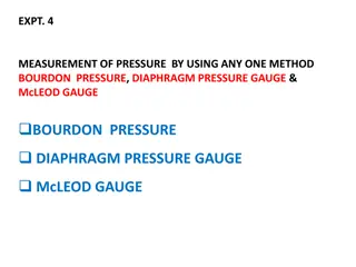
Calibration of Bourdon Gauge


Experiment 2
Calibration of Bourdon Gauge
By
Asst.Lectuer: Mohammed Abid Jameel


Ministry of Higher Education and Scientific
Research
Mustansiriyah University
College of Engineering
Water Resources Engineering Department
Fluid laboratory

1.
Introduction:
Burden Gauge is a mechanical device, it is using to measure the gases pressure which
trapping in a given space or the fluid which passing through the pipes, where, it measures the
difference between absolute pressure and atmospheric pressure. As a result of, much use for
this device, some its parts may be damaged, for this reason, we need to calibrate the device
by the calibration cylinder to ensure its measurement accuracy, then finding error in the
device, and correct the gauge reading.
2.
Objectives
:
1- To calibrate bourdon gauge device.
3.
Theoretical background (equations):
F = m× g……... (1)
F= The force (weight) delivered by weights or piston (N)
m= mass of weights or piston (Kg)
g = acceleration to the gravity (9.81 m/s
2
)
Note:
mass of piston: 1kg, weight of piston =9.81 N
P
actual
= F / A……… (2)
note:
Cross-sectional area = 333 mm
2
P
actual
= Actual Pressure (N/ m
2
)
F= Total force (weight) delivered by weights and piston (N)
A= Cross-Sectional Area of force delivered (m
2
)
Error = P
actual
- P
gauge
……… (3)
Error = the error in device reading
P
actual
= Actual Pressure (N/ m
2
)
P
gauge
=gauge Pressure (N/ m
2
)
Efficiency % = ( P
actual
- P
gauge
) / P
actual
)×100……… (4)
Efficiency %= the percentage of the error or efficiency in device reading
4.
Experimental Work:
4.1.
Equipment and apparatus:
Bourdon pressure gauge is consisting essentially from: (Figure 1)
1- Thin-walled tube of oval cross-section, which is bent to a circular arc encompassing
approximately 270'. It is rigidly held at one end, when the pressure is admitted. The other end
is free to move and is sealed. When pressure is applied, the tube tends to straighten, so that
the free end moves slightly. This movement operates a mechanism which drives a pointer
round the graduated dial, the movement of the pointer being proportional to the applied
pressure.
2- A cylindrical piston, free to move vertically in a closely-fitting cylinder (calibration
cylinder), is loaded with known weights.
3- The space below the piston is filled with oil, and the pressure is transmitted by the oil to
the gauge under test through transparent plastic tube.
4- Metal base for support the device.
Figure 1
4.2.
Procedure:
1-The weight of the piston, and its cross-sectional area, should be noted.
2- To full the cylinder, the piston is removed, and oil is poured into the
cylinder until it is full to the overflow level.
3- Any air trapped in the tube may be cleared by tilting and gently tapping the apparatus. In
point of fact. A small amount of air left in the system will not affect the experiment, unless
there is so much as to cause the piston to bottom on the base of the cylinder.
4- The piston is then replaced in the cylinder and allowed to settle. A spirit level placed on the
platform at the top of the pistol may be used to ensure that the cylinder stands quite vertically.
5-Weights are now added in convenient increments, and at each increment the pressure gauge
leading is observed. A similar set of results is then taken with decreasing weights. To guard
against the piston sticking in the cylinder, it is advisable to rotate the piston gently while the
pressure gauge is being read.
4
.
3
.
D
a
t
a
S
h
e
e
t
:
5.
Calculations and Results:
For two case weights adding and weights decreasing, we find:
1- The force (weight) delivered by weights or piston (F) (N).
2-The True Pressure (P
actual)
(N/ m
2
).
3- Calculate the error in device reading.
4- Calculate the percentage of the error or efficiency in device reading (Efficiency %).
5- Draw diagrams between True Pressure and gauge Pressure.
6- Draw diagrams between True Pressure and the percentage of the error or efficiency in
device reading (Efficiency %).
6
.
D
i
s
c
u
s
s
i
o
n
:
1- Is there a difference between actual pressure and gauge pressure? Why?
2- Is the efficiency of the device good to use? Why?
3- What is the relationship between actual pressure and efficiency? Why?
4- What is the relationship between the error in device reading and efficiency? Why?
Thnke you
Bourdon Gauge is a mechanical device used to measure gas pressure or fluid flow. In this experiment, the gauge is calibrated using known weights and a cylinder to ensure accurate measurements. The procedure involves filling the cylinder with oil, removing any trapped air, and noting the piston's weight and area. By comparing actual and gauge pressures, errors are determined and corrected to enhance gauge efficiency.

Download Presentation

Please find below an Image/Link to download the presentation.
The content on the website is provided AS IS for your information and personal use only. It may not be sold, licensed, or shared on other websites without obtaining consent from the author.If you encounter any issues during the download, it is possible that the publisher has removed the file from their server.
You are allowed to download the files provided on this website for personal or commercial use, subject to the condition that they are used lawfully. All files are the property of their respective owners.
The content on the website is provided AS IS for your information and personal use only. It may not be sold, licensed, or shared on other websites without obtaining consent from the author.
E N D
Presentation Transcript
Ministry of Higher Education and Scientific Research Mustansiriyah University College of Engineering Water Resources Engineering Department Fluid laboratory Experiment 2 Calibration of Bourdon Gauge By Asst.Lectuer: Mohammed Abid Jameel
1. Introduction: Burden Gauge is a mechanical device, it is using to measure the gases pressure which trapping in a given space or the fluid which passing through the pipes, where, it measures the difference between absolute pressure and atmospheric pressure. As a result of, much use for this device, some its parts may be damaged, for this reason, we need to calibrate the device by the calibration cylinder to ensure its measurement accuracy, then finding error in the device, and correct the gauge reading. 2. Objectives: 1- To calibrate bourdon gauge device.
3.Theoretical background (equations): F = m g ... (1) F= The force (weight) delivered by weights or piston (N) m= mass of weights or piston (Kg) g = acceleration to the gravity (9.81 m/s2) Note: mass of piston: 1kg, weight of piston =9.81 N Pactual = F / A (2) note: Cross-sectional area = 333 mm2 Pactual= Actual Pressure (N/ m2) F= Total force (weight) delivered by weights and piston (N) A= Cross-Sectional Area of force delivered (m2) Error = Pactual - Pgauge (3) Error = the error in device reading Pactual= Actual Pressure (N/ m2) Pgauge =gauge Pressure (N/ m2) Efficiency % = ( Pactual - Pgauge) / Pactual ) 100 (4) Efficiency %= the percentage of the error or efficiency in device reading
4.Experimental Work: 4.1. Equipment and apparatus: Bourdon pressure gauge is consisting essentially from: (Figure 1) 1- Thin-walled tube of oval cross-section, which is bent to a circular arc encompassing approximately 270'. It is rigidly held at one end, when the pressure is admitted. The other end is free to move and is sealed. When pressure is applied, the tube tends to straighten, so that the free end moves slightly. This movement operates a mechanism which drives a pointer round the graduated dial, the movement of the pointer being proportional to the applied pressure. 2- A cylindrical piston, free to move vertically in a closely-fitting cylinder (calibration cylinder), is loaded with known weights. 3- The space below the piston is filled with oil, and the pressure is transmitted by the oil to the gauge under test through transparent plastic tube. 4- Metal base for support the device.
4.2. Procedure: 1-The weight of the piston, and its cross-sectional area, should be noted. 2- To full the cylinder, the piston is removed, and oil is poured into the cylinder until it is full to the overflow level. 3- Any air trapped in the tube may be cleared by tilting and gently tapping the apparatus. In point of fact. A small amount of air left in the system will not affect the experiment, unless there is so much as to cause the piston to bottom on the base of the cylinder. 4- The piston is then replaced in the cylinder and allowed to settle. A spirit level placed on the platform at the top of the pistol may be used to ensure that the cylinder stands quite vertically. 5-Weights are now added in convenient increments, and at each increment the pressure gauge leading is observed. A similar set of results is then taken with decreasing weights. To guard against the piston sticking in the cylinder, it is advisable to rotate the piston gently while the pressure gauge is being read.
4.3. Data Sheet: Ran mass of weights or piston (kg) Pgauge (N/ m2) 1 2 3
5. Calculations and Results: For two case weights adding and weights decreasing, we find: 1- The force (weight) delivered by weights or piston (F) (N). 2-The True Pressure (Pactual) (N/ m2). 3- Calculate the error in device reading. 4- Calculate the percentage of the error or efficiency in device reading (Efficiency %). 5- Draw diagrams between True Pressure and gauge Pressure. 6- Draw diagrams between True Pressure and the percentage of the error or efficiency in device reading (Efficiency %).
Ran The force (F) (N). (Pactual) (N/ m2). Error Efficiency % 1 2 3
Pgauge Effic % Pactual Pactual 6. Discussion: 1- Is there a difference between actual pressure and gauge pressure? Why? 2- Is the efficiency of the device good to use? Why? 3- What is the relationship between actual pressure and efficiency? Why? 4- What is the relationship between the error in device reading and efficiency? Why?
Thnke you Thank you


:")