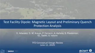
Explore the application of the Stream Model in analyzing the TF coil quench in WEST Tokamak at the ChATS Workshop 2021. Delve into the results, analysis, and conclusions of the research conducted by Sylvie Nicollet, A. Torre, B. Lacroix, A. Louzguiti, Q. Gorit & the WEST Team. Learn about the Toroidal Field Coil quench of Tore Supra/West Tokamak, the West TFC systems, and the hydraulic circuit analysis. Discover the advancements in superconducting coils technology and insights gained from over 30 years of successful operation.
Please find below an Image/Link to download the presentation.
The content on the website is provided AS IS for your information and personal use only. It may not be sold, licensed, or shared on other websites without obtaining consent from the author. If you encounter any issues during the download, it is possible that the publisher has removed the file from their server.
You are allowed to download the files provided on this website for personal or commercial use, subject to the condition that they are used lawfully. All files are the property of their respective owners.
The content on the website is provided AS IS for your information and personal use only. It may not be sold, licensed, or shared on other websites without obtaining consent from the author.
E N D
Presentation Transcript
DE LA RECHERCHE LINDUSTRIE STREAM MODEL APPLIED TO WEST TF COIL QUENCH ANALYSIS CHATS-AS Workshop 20-25/09/2021 Sylvie NICOLLET, A. Torre, B. Lacroix, A. Louzguiti, Q. Gorit & WEST Team Commissariat l nergie atomique et aux nergies alternatives - www.cea.fr Commissariat l nergie atomique et aux nergies alternatives
1 WEST TFC & QUENCH 2 STREAM MODEL 3 RESULTS & ANALYSIS 4 - CONCLUSION & FURTHER APPLICATION DE LA RECHERCHE L INDUSTRIE Commissariat l nergie atomique et aux nergies alternatives - www.cea.fr Commissariat l nergie atomique et aux nergies alternatives
WEST TFC SYSTEMS: 1st SUPERCONDUCTING COILS 18 TF Coils in NbTi cooled with static superfluid helium bath (1.8 K) I= 1400 A, Conductor (5,6 x 2,8 mm2) constituted by 11 000 strands of NbTi with a matrix of Cu-Ni Coil Number Major Radius Height Weight Self Inductance 613 H Stored Energy 601 MJ 18 2.442m 2.970m 162 t Since 1988: 1st Superconducting Coils More than 30 years of successfull operation with only 2 quench 3 Commissariat l nergie atomique et aux nergies alternatives
TOROIDAL FIELD (TF) COIL QUENCH OF TORE SUPRA/ WEST TOKAMAK Toroidal Field (TF) of Tore Supra/West Tokamak Quench 18 NbTi superconducting coils carrying a current of 1255A cooled by a static superfluid helium bath at 1.8 K operating since 1988 in CEA/ IRFM (Cadarache). CHATS 2019 Paper WEST TF quench analysis SuperMagnet Results: WP CICC-like coil model (void=0.405) Monolithic conductor: NbTi/Cu/CuNi 2.8 x 5.6 mm 11000 filaments - 1400A Superconducting Coils: av. 2.6 m 2.5 t 26 double-pancakes, 39 turns, 2028 spires Stainless Steel thick Casing: ext : 3.3 m 6.6 t 18 Coils: 165 t , L tot : 613 H (4.5T at plasma radius) I Op : 1255A, B Op : 8.1T E tot : 479 MJ (3.9T at plasma radius) 19th december 2017, at end of Plasma N 52205 (14:02:59) quench on BT09 detected first on an helium liquid level (TNL) triggered a current fast discharge. Voltage quench detection (V) was at that time nearly to be trigerred. High Energy Runaway electrons (30 MeV) (+ disruption at Plasma end) which collided on outboard plasma facing components creating high neutron and gamma flux : Energy in Coil=1.3 kJ 4 Commissariat l nergie atomique et aux nergies alternatives
WEST TFC QUENCH ANALYSIS: HYDRAULIC CIRCUIT CHATS 2019, Cryogenics 106 (2020) 103042, S. Nicollet: Thermohydraulic Analysis of Tore Supra / WEST TF Coil Quench: Associated Smooth Quench Occurrence in Tokamak WEST TFC09 Quench SuperMagnet Model Analysis Initial quenched length: 0.4 m @ x=2 m (2.6 s duration), Model Voltage threshold:100 mV Initial number of quenched conductors: ~100 / 2028 8 m TORE SUPRA / WEST TFC QUENCH DETECTION PARAMETERS Symbol Measurements V Voltage, Comparison 2 to 2 T Temperature on HeII Bath TNL Temperature "Liquid Level" P Pressure on He II Bath 5 m Security Threshold time delay 2 V 1,98 K 1,95 K 1,88 bar 1 s 1 s 1 s 0,2 s 5 Commissariat l nergie atomique et aux nergies alternatives
WEST TFC QUENCH ANALYSIS: SUPERMAGNET & GEANT4 MODELS Runaway electrons of High Energy (30 MeV): GEANT4: disruption + runaway high neutron & gamma flux E=6,84 kJ (thick casing) & 1,3 kJ (Coil WP). WEST TFC SuperMagnet model (Coil CICC-like THEA model in bath) Coil helium pressure comparison, depending on Minimum Quench Energy Small initiation zone: dL ~0.4 m, dY ~0,24 m and dR ~ 1 cm. Calculated = Observed expulsed helium mass flow=5 kg/s Initial number of quenhed conductors: ~ 100 / 2028 confirms criticality and the possible occurrence of smooth quench (small heat deposition length at low field region). Secondary detection (thermohydraulic) more rapid than Voltage primary detection WEST TF magnet integrity has been confirmed and has reoperated since 2018. Cryogenics 106 (2020) 103042, S. Nicollet: Thermohydraulic Analysis of Tore Supra / WEST TF Coil Quench: Associated Smooth Quench Occurrence in Tokamak 6 Commissariat l nergie atomique et aux nergies alternatives
STREAM MODEL OBJECTIVES : ANALYTICAL MODEL WITH EXPLICIT RESOLUTION MORE RAPID IN EXECUTION TIME VALIDATION WITH EXPERIMENTAL RESULTS, CROSSCHECK WITH SUPERMAGNET MODEL AS WELL ALL QUENCH MACRO-PARAMETERS ENGINEERING APPROACH STREAM: SUPERCONDUCTOR THERMOHYDRAULICAL AND RESISTIVE ELECTRICAL ANALYTICAL MODEL (CEA-IRFM, S. Nicollet, Matlab) STREAM describes electrical, thermodynamical (thermal) & hydraulical analytical equation during quench Electrical model, describes evolution of quenched length Lq, Joule heating in conductor (>Tcs), resistance, voltage and decrease of current (from voltage threshold criteria). - first thermal and thermodynamical phase describes evolution of helium pressure & temperature in closed volume, with heatedpart (Vh with external Joule energy deposited) & other cold part submitted to isentropic compression (Vc remains adiabatic). - second hydraulical phase describes helium mass flow expulsion, from given pressure drop threshold, through relief circuit with limitation at atmospheric pressure or Mach = 1 7 Commissariat l nergie atomique et aux nergies alternatives
STREAM MODEL STREAM: SUPERCONDUCTOR THERMOHYDRAULICAL AND RESISTIVE ELECTRICAL ANALYTICAL MODEL STREAM Model Main Characteristics - Computer code used for thermodynamic helium properties. - STREAM model: 0-D model (no space discretization in Winding Pack). Only two volumes hot and cold considered with corresponding temperatures. - The resolution is explicit - The final (or next time step) heated and non heated volume (inside the coil) are at the same pressure: PHe,c (t) = PHe,h (t) = PHe (t) - Safety valves models: PCLAP = pressure set of magnetic safety disc) for P < PCLAP, MF = 0 (Helium Mass Flow) for P > PCLAP, valve is open. If P < PCLAP after valve opening, reduced section for spring valve - The code can take into account a shock wave - Pressure drop & heat transfer coefficients in exhaust pipe determined using experimental results. 8 Commissariat l nergie atomique et aux nergies alternatives
STREAM ELECTRICAL MODEL QUENCH PROPAGATION : SHAJII FREIDBERG MODEL, SHORT COIL LOW PRESSURE REGIME FOR WEST TFC QUENCH 2 ?? ??=? ?0 ?0 ??? 2 ?0 CONDITIONS IN CICC LENGTH & PRESSURE INCREASE 1st Phase 2nd Phase 2 ?? ?2<24 ? ?0 ? ?0= ? ?0 ? 4 ? ?0 ??2< 1 ? ?? A. Shajii, Universal Scaling Laws for Quench and Thermal Hydraulic Quenchback in CICC Coils, IEEE, June 1995. ?????????? ??=???????? ?0 ??? ?0= ????= ?0: ????????( ? = ???????+ ???????+ ?????????? 2 For both Phases: Jcu=I/Acu= (2028*1255 A)/0.0227m = 112.098 A/m , 0 =4.49 10-15 First phase : P0=1.3 bar, T0=1.7 K, 0= 147.6 kg/m3, Lq,ini=0.0246 m quench propagation velocity Vq=1.636 m/s Second phase : P0=1.3 bar, T0=110 K, 0= 0.6 kg/m3, Lq,ini=2.5 m quench propagation velocity Vq=0.640 m/s. VERY SIMPLE ELECTRICAL CORRELATION ???????? = ???????? ? ,?????,??????? ????+ ?????????? ,?????,??????? (1 ????) ??????(?) = ???????(?) ??(?) ????/???,???? ??????(?) = ??????(?) ??????(?) (? ??????+??????? ?) ??????? ??????? = ???? ? ???= ? ? ? ? ?? (? ??????+??????? ?) ??????? ??????? = ???? ? 9 Commissariat l nergie atomique et aux nergies alternatives
STREAM HYDRAULICAL MODEL If PHE > PCLAP in first tube and non-adiabatic in second tube, limited to Patm or Mach=1. Uniform Fluid Flow in one dimension, with viscosity and friction forces, compressible and adiabatic GENERAL HYDRAULICAL FORMULA & LOOP on MASS FLOW MF(t) & ABSCISSA X ALONG THE FLOW PATH ?? (?) ?? ???= ( ?? ??? ?? ???) ???,? ??????,? ???,?? = ??? = ??,??,???,??,? ( ??,?? ??) ??? ?= EXPRESSION OF PRESSURE EVOLUTION ALONG HYDRAULIC PATH 2 ????,? ?? ??? ? 1 ??? ? = ??,?? ????1?? + ????2?? + ????3?? 2 )/( ??,?? ?? ?? ????1?? = ( ??? 1 ???,?? ??,??,? ?????,? ???,?? ???,?? ? ?) 2 ????3?? = (??????,? ??? ?? 2 ?? ??????,? (2 ? ,?) ( ??? 1 ???,?? 2 ? ????2?? = ??? ? + 1) ?? ??,? ??? EXPRESSION OF DENSITY, VELOCITY & TEMPERATURE EVOLUTION ALONG HYDRAULIC PATH ? ??,? ?? ??? ??2 ???,? ??? ?? ?? ??,? 2 ? ,? ( ??,? ??? ?? ?? ???,? ? ??,? ?? ? ? ?? ?P ????,? = + ?? ????,?= ? ??,? + ????,?= ??,? ENERGY BILANCE ON EXHAUST TUBES AND RELIEF VALVES ???,?(? + ??) = ???,?(?) + (??????,??,?(?)/(?? ??? ??? ????)) ??????,??,?(?) = ?????,? ??,??,?? ?? ???,?? ???,?(?) ?? END LOOP IN X AND MASS FLOW: EVOLUTION OF MASS ???? + ?? = ???? ?? ? ?? 11 Commissariat l nergie atomique et aux nergies alternatives
WEST TFC MINIMUM QUENCH ENERGY & NORMAL LENGTH 3-D 0-D 1-D Thea GEANT4 Runaway GEANT4 Runaway SuperMagnet Gamma + Neutron Gamma + Neutron STREAM P_VOL MQE P_lin Length AHe Acond duration Energy Number Etot DV_QD Hconv T_gradients (W/m3) W/m (m) (m ) (m ) (s) (J) (-) (kJ) (V) (W/m K) 424673 25350 385305 23000 900000 53724 0.4 0.4 0.4 0.4 0.027894 0.031799 0.027894 0.031799 0.027894 0.031799 2.6 2.6 2.6 1300 100 26364 2028 26.3640 23920 2028 23.9200 55873 2028 55.8726 0.1 2 2 2 500 peak 50 peak peak global Tquench Tquench Ncond ~100 Ncond =2028 First Phase: Vq=1.636 m/s Until 2.5 or 3 m (nearest 1st extremity ) Second Phase: Vq=0.640 m/s Tini Tini STREAM MQE HconvE_2.5 K-Tcs~ 2 *THEA MQE (temperature gradients) 12 Commissariat l nergie atomique et aux nergies alternatives
WEST TFC QUENCH ELECTRICAL RESULTS Measurements: Blue STREAM Calculated Results: Red SuperMagnet Calculated Results: Orange Maximum Voltage: 1400 V Coil dissipated Energy: ~18 MJ Calculated Coil Resistance: ~5 (magneto-resistance & Td=120 s) Calculated STREAM & SuperMagnet Electrical Results in good agreement with Measurements (or Values deduced from measurements) 13 Commissariat l nergie atomique et aux nergies alternatives
WEST TFC QUENCH THERMOHYDRAULICAL RESULTS Measurements: Blue STREAM Calculated Results: Red SuperMagnet Calculated Results: Orange Maximal Pressure upstream CSV: 1.0 MPa (SuperMagnet controlled PHeat 0.4 MPa) Maximal Conductor Hot Spot Temperature: 110 K Average Temperature: 80 K Maximal Temperature upstream cold safety valve (CSV) : 50 K (good dynamics at 10 K) Calculated STREAM & SuperMagnet Thermohydraulical Results in good agreement with Measurements (or Values deduced from measurements) 14 Commissariat l nergie atomique et aux nergies alternatives
WEST TFC QUENCH COMPLEMENTARY THERMOHYDRAULICAL RESULTS Measurements: Blue STREAM Calculated Results: Red SuperMagnet Calculated Results: Orange Mach Number limited to 1 (or slightly over after 50 s: minimal MF imposed limit) Massflow of 5 kg/s during 5 s !! (total helium mass/volume ~ 25+5 kg / 200+40 l ) STREAM & SuperMagnet Calculated Results in good agreement with Measurements (or values deduced from measurements) 15 Commissariat l nergie atomique et aux nergies alternatives
CONCLUSION & FURTHER STREAM APPLICATION Superconductors Thermohydraulical and Resistive Electrical Analytical Model (STREAM) successfully developed for coils cooled in static superfluid helium bath Electrical, Thermodynamical (isentropic compression) & Hydraulical model (expulsed helium mass flow limited at Patmor Mach = 1) STREAM Validation: WEST TFC Quench STREAM Calculated Results show good agreement with the measurements results or deduced from measurements (& SuperMagnet Calculated Results) STREAM important interest (Calculation ~10 min / SuperMagnet Calculation for WEST ~hours/days) STREAM usefull for Tokamak magnets quench studies and safe operation STREAM developments & application to CICC Coil Configuration JT-60SA TFC in CTF and Tokamak: Q. Gorit, Publication at CHATS-AS 2021, ITER Coils, DEMO, etc Application to Cryostat Vacuum Loss Incident Analysis (JT-60SA EF1- helium leaks and Cryostat Vacuum Pressure increase) 16 Commissariat l nergie atomique et aux nergies alternatives
Merci de votre attention DE LA RECHERCHE L INDUSTRIE Commissariat l nergie atomique et aux nergies alternatives - www.cea.fr Commissariat l nergie atomique et aux nergies alternatives
WHAT IS A QUENCH ? Irreversible transition from superconducting state to normal resistive state Large energy dissipation due to Joule heating If not quickly detected, possible permanent damage of the magnet Starting from a localized perturbation, the normal (quenched) zone propagates and generates a large resistive power He inlet He outlet 2 methods for quench detection: Electrical signature (resistive voltage) fastest method, so primary detection Thermo-hydraulic signature (He mass flow, pressure, temperature) secondary detection Voltage compensation (from coil to coil) to discriminate resistive voltage from magnetic disturbances Courtesy of IRFU/SACM CEA Saclay 18 Commissariat l nergie atomique et aux nergies alternatives
FEATURES OF PRIMARY DETECTION V(t) & I(t) 3,0 3,0E+04 4 phases for a protection sequence: Propagation p(Ut) Filtering phase holding time h Current breakers opening cb Fast Safety Discharge of the current ( FSD) for dumping magnetic energy (1.06 GJ for 18 TF coils) into an external resistor Fast Safety Discharge of the current 2,5 2,5E+04 1. 2,0 2,0E+04 2. Current (A) voltage (V) Voltage (V) Resistive 3. 1,5 1,5E+04 4. 1,0 1,0E+04 Ut= 0.5 V 0,5 5,0E+03 Voltage Current 0,0 0,0E+00 p 0 5 10 15 time (s) h+ cb da = p + h + cb A high propagation velocity is Primary detection parameterization = setting the values (Ut, h) favourable for quench detection Hot spot criterion (maximal acceptable Tcond) detection and action time da p(Ut) requires a reliable simulation of quench propagation Choice of the voltage threshold Ut p(Ut) h = da p(Ut) cb 19 Commissariat l nergie atomique et aux nergies alternatives
WEST TFC QUENCH: COMMON STREAM & SUPERMAGNET PARAMETERS Name Monolithic Conductor Material Electrical characteristics and STREAM Parameters Type of strand Number of SC cable (equivalent to CICC Strands, NTot) Copper RRR (RRRCu) Conductor Dimensions dY / dR Conductor Operating Current Iini Model Winding Pack Operating Current Iini Coil minimum magnetic field Bini Current sharing Temperature (Tcs) Voltage Quench Detection Threshold (DVdetect) Voltage Quench Detection Time (Tdelay) Equivalent Current discharge time constant (Taudum) WP Total Conductor Cross section (ACond) Superconducting Conductor (Strands) Cu/non-Cu ratio WP Cu and CuNi Cross section (ACU) WP NbTi Cross Section (ANbTi) Cable components NbTi / Cu / CuNi Thermal (Thermodynamical) characteristics Parameters (Coil) Superfluid Helium Bath Temperature/ Pressure Hydraulic Length (Inner Radius) WP Helium Volume WP Helium initial Mass Toro dal (Y) / Radial (R) axis Thin Case Dimensions Thin Case Stainless Steel Cross Section (ASS) Thin Case Stainless Steel-Helium Wetted Perimeter (Pw,SS) Winding Pack Total Insulation Cross Section (AIN) Toro dal (Y) / Radial (R) axis WP Dimensions WP Insulation Helium Wetted Perimeter (Pw,IN) WP Helium Cross Section (AHE) WP Conductor-Helium Wetted Perimeter (Pw,He) WP Helium Hydraulic Diameter (DhHE) WP Helium Void fraction Vf Cupper / NbTi, SS volumetric mass Value (1ere OK) NbTi/Cu/CuNi NbTi 2028 100 2.8 / 5.6 1255 1255*2028=2545.103 5.5 6.5 2 1 18 0.031799 0.0227045 or 0.02258 0.0090945 or 0.00922 29 / 64 / 7 Units mm / mm A A T K V s s m m m % and STREAM 1.69 / 0.13 7.17 0.176 25.98 0.27725 / 0.24962 0.00210748 / 0.0026848 1.05374 or 1.3424 0.00950801 0.25525 / 0.22715 19.8588 0.0245467 or 0.02789 34.0704 0.002882 or 0.00335 0.3612 or 0.4048 8960 / 6012 / 7900 K / MPa m m3 kg m / m m m m m / m m m m m Kg/m3 20 Commissariat l nergie atomique et aux nergies alternatives
WEST TFC QUENCH: STREAM PARAMETERS Name TSWEST Coil STREAM Hydraulical Parameters Initial Ratio of hot volume over total volume Initial helium Pressure / Temperature Convective heat exchange coefficient in Coil Initial external volumetric deposited Power Initial external deposited power length External depositied energy duration CvCp Ratio for constant volume and mix evolution TSWEST Coil STREAM Electrical Parameters Coil Current Coil Magnetic Field Current sharing temperature Initial quenched Length Quenched Length exponential propagation time cste TSWEST expulsed circuit STREAM Hydraulical Parameters Pressure Threshold Value Stainless Steel Tube Thickness Cold safety Valve (CSV) chracteristics CSV tube Length CSV friction factor CSV Helium Section CSV Hydraulic Diameter CSV Initial Stainless Steel Tube Temperature Upstream Cold Tube (UCT) Characteristics Upstream tube Length Upstream tube friction factor Upstream tube Helium Section Upstream Tube Hydraulic Diameter Upstream Tube Initial Stainless Steel Tube Temperature Downstream Warm Tube (DWT) Characteristics Dowstream tube Length Dowstream tube friction factor Dowstrem tube Helium Section Downstream Tube Hydraulic Diameter Downstream Tube Initial Stainless Steel Tube Temperature Warm Spring Valve (WSV) Characteristics WSV tube Length WSV tube friction factor WSV tube Helium Section WSV Tube Hydraulic Diameter WSV Initial Stainless Steel Tube Temperature Warm Spring Valve (WSV) Reduced Section Characteristics Ratio of reduced Section WSV reduced section tube Length WSV reduced section tube friction factor WSV reduced section tube Helium Section WSV reduced section Tube Hydraulic Diameter TSWEST STREAM Code Parameters Time step Abscissa calculation step Parameters R VOL P He / T He Hconv Q VOL LNG,ini tNG R CvCp I 0 B 0 T cs L q,ini t q,prop P CLAP e SS L0 F0 A0 Dh0 T SS,L0 L1 f1 A1 Dh1 T SS,L1 L2 f2 A2 Dh2 T SS,L2 L3 F3 A3 Dh3 T SS,L3 NAreduced L3,bis F3,bis A3,bis Dh3,bis dt dx Values 0.7 0.13 / 1.69 50 900 0.4 2.6 1 / 0.5 1255 5.5 6.5 0.01 10 0.4 0.002 0.5 0.08 10*10-4 0.02 2.5 8 0.3 40.8*10-4 0.0721 2.5 5 0.1 40.8*10-4 0.0721 300 0.5 0.1 15*10-4 0.0437 300 8 =L3 = F3 = A3 /NAreduced^2 =Dh3 / NAreduced 0.002 0.25 Unit MPa / K W/m K kW/m3 m s - A T K m s MPa m m - m m K m - m m K m - m m K m - m m K - m - m m s m 21 Commissariat l nergie atomique et aux nergies alternatives
WEST TFC QUENCH COMPLEMENTARY RESULTS Time between t0 quench & t0FD: 3.5 s Maximal Pressure in Coil: 1.6 MPa (SuperMagnet: controlled PHeat 0.4 MPa) Volumetric Ratio evolution 22 Commissariat l nergie atomique et aux nergies alternatives
WEST TFC QUENCH HEAT FLUX Calculated SuperMagnet Heat Flux Maximal long duration (10 s) value near 1500 W/m Calculated STREAM Heat Flux Maximal long duration (10 s) value near 1100 W/m 23 Commissariat l nergie atomique et aux nergies alternatives
SUPERMAGNET CODE SuperMagnet Code [1] developed by Luca Bottura (CERN) and commercialized by Horizon Technology (John Persichetti, USA),FORTRAN Code The CryoSoft suite of codes THEA [2] (Thermal, Hydraulic and Electric Analysis of Superconducting Cables), FLOWER [3] (Hydraulic Network Simulation), POWER (Electric Network Simulation of Magnetic Systems), and HEATER provides a basis for well optimised and flexible tools for the analysis of specific issues in superconducting magnet systems. SUPERMAGNET is the manager application that launches two or more of the above codes, schedules their communication and terminates execution as appropriate. The codes communicate through a data exchange mechanism that achieves the desired physical coupling and makes it possible to describe a series of processes such as: effect of helium expulsion during thermal transients on the proximity cryogenics; evolution of the coil current during quench, including the effect of quench resistance; cooling of a coil with thermally coupled parallel channels; [1] Bagnasco M et al. Progress in the Integrated Simulation of Thermal-Hydraulic Operation of the ITER Magnet System. IEEE Transactions on Applied Superconductivity 2010; 20-3: 411-414. 24 Commissariat l nergie atomique et aux nergies alternatives
THEA CODE Geometrical Description of Cable-In-Conduit Conductor (A, Ub, Dh) Implementation in subroutines: CICC friction factors, from measurements at room temperature on each conductor CICC Heat exchange coefficient COLBURN Pancakes Magnetic Field Strands Performances NbTi Jc (B, T) with L. Bottura Law, strands of average performances (identical) Heat load from casing to Pancakes (lateral + central) Eventually, Initiation of Quench by local perturbation Coil Current Parameters of quench detection & Current safety discharge THEA Parameters THEA Code [1] is the numerical implementation of a 1-D model for the thermohydraulic simulation of Cable In Conduit Conductor : Mass, momentum and energy balance with Compressible fluid Model of 4 independent components: the strands, the conduit, the bundle helium and central helium. I, B (x,t) during quench, the Joule heat generation is computed consistently with the non-linear critical current density correlation. The solver decides whether a quench or a recovery has taken place. [2] L. Bottura et al., A numerical model for the simulation of quench in the ITER magnets, Journal of Computational Physics 125, 26-41, Article N 0077, 1996. 25 Commissariat l nergie atomique et aux nergies alternatives
FLOWER CODE FLOWER Code Implementation & Description of Cryogenic Components: JUNCTIONS (1-D with compressible fluid) defined by (P, T, v) Cryolines, manifolds & tubes Control Valve, quench relief valve (Burst Disk with pressure set), check valve Heat exchangers Pumps Possibility of a additional heater (JT-60SA CTF: increase of The,inlet until T=7,5 K) VOLUMES (0-D) defined by (P, T) Tank (relief) Additional connection volumes between 2 Junctions Each Junction is connected to 2 Volumes Each Volume is connected to minimum 2 Junctions [3] Bottura L, Rosso C. Flower a model for the Analysis of Hydraulic Networks and Processes. CHATS Workshop, Cryogenics, 2003; 43: 215-223. 1 THEA / Pancake 26 Commissariat l nergie atomique et aux nergies alternatives
CONTEXT: OBJECTIVES & CODES OPERATION: SLOW TRANSIENTS THEA / SimCryogenics (IRIG/DSBT) QUENCH INCIDENT: FAST TRANSIENTS SUPERMAGNET (CERN, L. Bottura, Ref ITER) THEA: 1-D CICC Model Advantages: - Precise Thermal, Hydraulic and Electric Analysis of Superconducting Cables, and Cryogenic components - Finite element model in space, finite difference in time Disavantages: - Large calculation time consuming - Forced flow CICC Quench: few hours - Bath cooled coil Quench: 5 days FLOWER: Cryodistribution Model Advantages: - More realistic tool for normal operation - PID Automatic control (P,T, M) - JT-60SA Refrigerator available SimCryogenics models Disadvantages - Coupling difficulty with THEA - Only valid for SLOW TRANSIENTS - Difficulty Quench Modelling QHe,St(pst, hst) Strand (Tst) Helium (P, THe, v) QHe,jk(pjk, hjk) QSt,jk (pSt,jk, hSt,jk) Jacket (Tjk) OBJECTIVES OF STREAM: ANALYTICAL MODEL WITH EXPLICIT RESOLUTION MUCH MORE RAPID IN EXECUTION TIME (10 min) CROSSCHECK WITH SUPERMAGNET MODEL AS WELL ALL QUENCH MACRO-PARAMETERS ENGINEERING APPROACH 27 Commissariat l nergie atomique et aux nergies alternatives
JT-60SA EF1 INCIDENT (09/03/2021): RAPID CRYOSTAT VACUUM LOSS & PRESSURE INCREASE LAVAL NOZZLE: VACUUM PRESSURE PVAC(t) CALCULATION IN STREAM LAVAL NOZZLE IMPLEMENTED IN STREAM CODE PHe Initial in Coil= 0.5 MPa, PVAC ini =4.3 10-5 Pa, TVAC ini =300 K VVAC in Cryostat =1410 m3, V He,Coil=3 m3, M He,Coil~400 kg (EF1,2,3+CS1,2) Crack or hole section S= 2.835mm Crack Diameter=1.9 mm Crack Diameter=1.9 mm DP DPVAC ~800 Pa in 9000s (2.5h Pa in 9000s (2.5h) ) MF MF Crack,max = 40 g/s ? 1 ? ? 1 ??? 2? ????(?) ??? ? = ? ? 1 ? ????(? + ??) = ????(?) +(??????? ?? ???? ????) (??? ????) VAC~800 Crack,max = 40 g/s 28 Commissariat l nergie atomique et aux nergies alternatives
PASCHEN LAW ??? ? = ) ? ln(?? 1torr=133.32 Pa DV min~100V JT-60SA Cryostat~ qqs torr*cm ? ? = ? ?? ? = ?? ? ? Gaz H2 N2 Air He Ne Ar A (Torr-1 cm-1) 5 12 15 3 4 14 B (V Torr-1 cm-1) 130 342 365 34 100 180 kB=1.380649 10-23 J K-1, constante de Boltzman R=NA*kB=8.31442618 J mol -1 K -1 NA=6.02214076 10 23mol -1, Nombre d Avogadro 29 Commissariat l nergie atomique et aux nergies alternatives


 COIL QUENCH OF TORE SUPRA/ WEST TOKAMAK")


: RAPID CRYOSTAT VACUUM")