AG3000 Horizontal Installation Overview
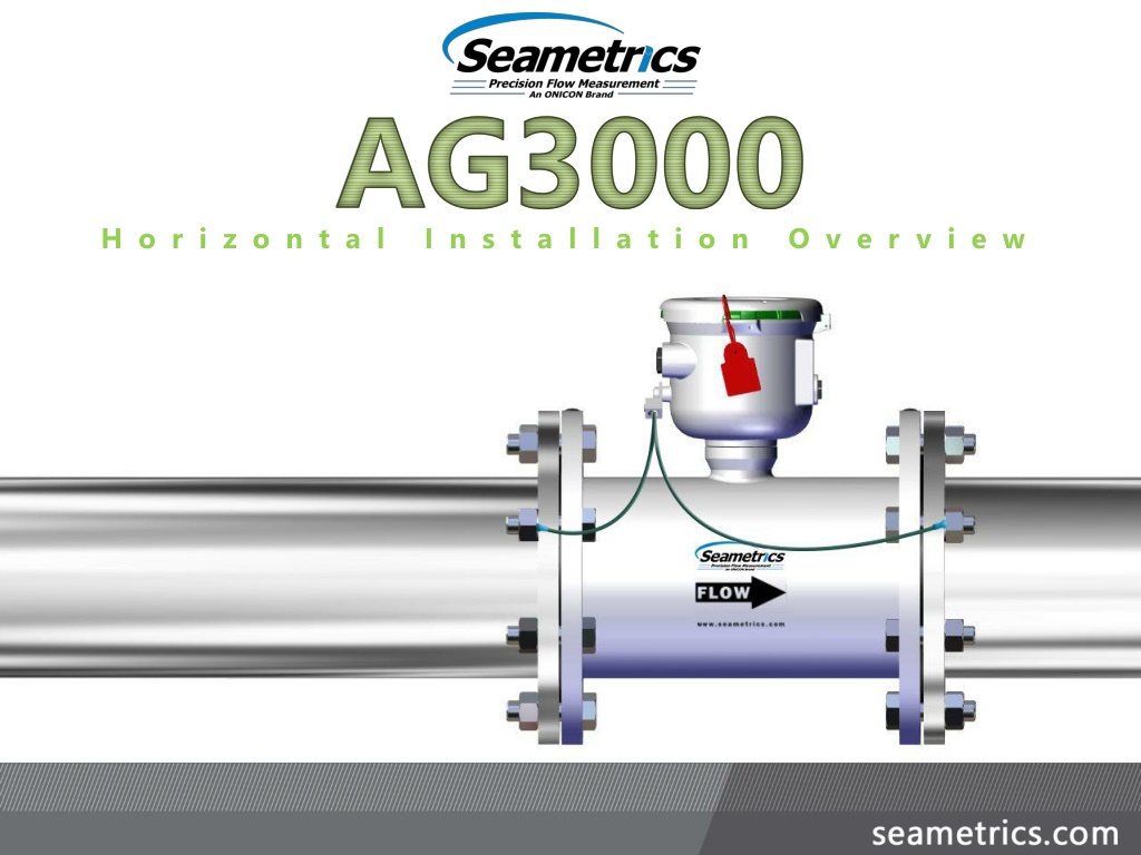
Horizontal Installation Overview
Step 1
Step 1
You’ll Need:
You’ll Need:
Measure the horizontal straight pipe from pump.
Ensure there is sufficient straight pipe to meet the
requirements of the meter.
AG3000-300 22“ total minimum straight pipe
AG3000-400 22“ total minimum straight pipe
AG3000-600 30" total minimum straight pipe
Tape Measure
Installing an
AG3000
Total minimum straight pipe for your meter – see below.
Meter + Flanges
+ Gaskets
+ Grounding rings
AG3000-800 38" total minimum straight pipe
AG3000-1000 48“ total minimum straight pipe
AG3000-1200 60" total minimum straight pipe
2X Pipe Diameter
Upstream
1X Pipe
Diameter
Downstream
Cut out a section of straight pipe, insuring there are at
least two pipe diameters of straight pipe on the inlet
side of the meter, and one pipe diameter of straight
pipe on the outlet side of the meter.
Tape Measure
Cutting Tools
Installing an
AG3000
Step 2
Step 2
You’ll Need:
You’ll Need:
This meter is sensitive to
heat
. Do not
weld or flame cut within 10’ of meter.
Heat will damage electronics and liner.
(Heat damage will void warranty.)
Meter + Flanges
+ Gaskets
+ Grounding rings
2X Min. Pipe Diameter
Upstream
1X Min.
Pipe
Diameter
Down
Cut out a section of straight pipe, ensuring there are at
least two pipe diameters of straight pipe upstream of
the meter, and one pipe diameter of straight pipe
downstream of the meter.
Tape Measure
Cutting Tools
Installing an
AG3000
Step 3
Step 3
You’ll Need:
You’ll Need:
2X Min. Pipe Diameter
Upstream
1X Min.
Pipe
Diameter
Down
This meter is sensitive to
heat
. Do not
weld or flame cut within 10’ of meter.
Heat will damage electronics and liner.
(Heat damage will void warranty.)
Meter/Flanges/
Gaskets/
Grounding rings
Weld the appropriate ANSI pattern flanges on each
open end of pipe, ensuring the flanges are parallel, and
the flange bolt holes are aligned.
Allow the welds to cool to ambient temperature.
Tape Measure
Welding Tools
Level
Installing an
AG3000
Step 4
Step 4
You’ll Need:
You’ll Need:
This meter is sensitive to
heat
. Do not
weld or flame cut within 10’ of meter.
Heat will damage electronics and liner.
(Heat damage will void warranty.)
Weld the appropriate ANSI pattern flanges on each
open end of pipe, ensuring the flanges are parallel, and
the flange bolt holes are aligned.
Allow the welds to cool to ambient temperature.
Tape Measure
Welding Tools
Level
Installing an
AG3000
Step 5
Step 5
You’ll Need:
You’ll Need:
WARNINGS:
THE HEAT AND/OR ELECTRICAL
CURRENTS FROM THE WELDER
WILL DAMAGE THE METER
AND VOID THE WARRANTY.
THE PIPE MUST NOT EXTEND
PAST THE SURFACE OF THE
FLANGE
Ensure bolt holes
are aligned
This meter is sensitive to
heat
. Do not
weld or flame cut within 10’ of meter.
Heat will damage electronics and liner.
(Heat damage will void warranty.)
Flow arrow
points
downstream
Torque
Wrench
Installing an
AG3000
FLOW
Step 6
Step 6
You’ll Need:
You’ll Need:
Install only with full face gasket on each
end of the meter.
Insert the meter, gaskets and grounding rings (if
applicable), with the direction arrow on the side of the
meter pointed down stream in the direction of the
flow.
Although the meter is shown
installed in the 12:00 position
for visual purposes, which is
acceptable, the ideal
installation is to rotate the
meter one bolt hole to a
slightly angled position.
Bolt the meter to the flanges using the appropriate
sequence and torque.
Installing an
AG3000
Step 6
Step 6
You’ll Need:
You’ll Need:
AG3000-300 25 ft-lb
AG3000-400 20 ft-lb
AG3000-600 42 ft-lb
AG3000-800 65 ft-lb
AG3000-1000 73 ft-lb
AG3000-1200 97 ft-lb
Torque
Wrench
Install the equalization wires and tabs from the lug to
the outside pipe flanges (not in direct contact with the
meter) for proper electrical grounding.
Wire Cutters
Tab on pipe flange
NOT
meter flange
Tab on pipe flange
NOT
meter flange
Installing an
AG3000
Step 7
Step 7
You’ll Need:
You’ll Need:
Torque
Wrench
#2 Phillips
Screw Driver
Install the equalization wires and tabs from the lug to
the outside pipe flanges (not in direct contact with the
meter) for proper electrical grounding.
Wire Cutters
Installing an
AG3000
Step 8
Step 8
You’ll Need:
You’ll Need:
Ensure proper
grounding.
See instruction manual for
more information on grounding
the meter.
Torque
Wrench
#2 Phillips
Screw Driver
If cables from meter to other electronics will be
needed in the field, install cables. See manual for
specific wiring requirements for your application.
Wrench
Wire Cutters
Installing an
AG3000
Step 9
Step 9
You’ll Need:
You’ll Need:
Inspect and clean O-ring and
threads on plastic wire gland
and cap.
#2 Phillips
Screw Driver
If meter does not have a factory installed hinged
weather guard, attach the weather guard cover and
lanyard.
Installing an
AG3000
Step 10
Step 10
You’ll Need:
You’ll Need:
Connect the security seal.
Installing an
AG3000
Step 11
Step 11
You’ll Need:
You’ll Need:
Your meter is installed!
Refer to the Seametrics AG3000 Instruction Manual for
additional information and programming instructions.
Installing an
AG3000
Step 12
Step 12
You’ll Need:
You’ll Need:
For Additional Support Call: 800-975-8153
Learn how to install the AG3000 meter horizontally with detailed steps including pipe requirements, cutting instructions, welding guidelines, and important precautions to prevent damage to the meter. Follow these steps for a successful installation process.

Download Presentation

Please find below an Image/Link to download the presentation.
The content on the website is provided AS IS for your information and personal use only. It may not be sold, licensed, or shared on other websites without obtaining consent from the author.If you encounter any issues during the download, it is possible that the publisher has removed the file from their server.
You are allowed to download the files provided on this website for personal or commercial use, subject to the condition that they are used lawfully. All files are the property of their respective owners.
The content on the website is provided AS IS for your information and personal use only. It may not be sold, licensed, or shared on other websites without obtaining consent from the author.
E N D
Presentation Transcript
AG3000 H o r i z o n t a l I n s t a l l a t i o n O v e r v i e w
Step 1 You ll Need: Total minimum straight pipe for your meter see below. Tape Measure Meter + Flanges + Gaskets + Grounding rings 1X Pipe Diameter Downstream 2X Pipe Diameter Upstream AG3000-300 22 total minimum straight pipe AG3000-800 38" total minimum straight pipe AG3000-400 22 total minimum straight pipe AG3000-600 30" total minimum straight pipe AG3000-1000 48 total minimum straight pipe AG3000-1200 60" total minimum straight pipe Measure the horizontal straight pipe from pump. Ensure there is sufficient straight pipe to meet the requirements of the meter. Installing an AG3000
Step 2 You ll Need: 1X Min. Pipe Diameter Down Meter + Flanges + Gaskets + Grounding rings 2X Min. Pipe Diameter Upstream Tape Measure Cutting Tools This meter is sensitive to heat. Do not weld or flame cut within 10 of meter. Heat will damage electronics and liner. (Heat damage will void warranty.) Cut out a section of straight pipe, insuring there are at least two pipe diameters of straight pipe on the inlet side of the meter, and one pipe diameter of straight pipe on the outlet side of the meter. Installing an AG3000
Step 3 You ll Need: 1X Min. Pipe Diameter Down Meter/Flanges/ Gaskets/ Grounding rings 2X Min. Pipe Diameter Upstream Tape Measure Cutting Tools This meter is sensitive to heat. Do not weld or flame cut within 10 of meter. Heat will damage electronics and liner. (Heat damage will void warranty.) Cut out a section of straight pipe, ensuring there are at least two pipe diameters of straight pipe upstream of the meter, and one pipe diameter of straight pipe downstream of the meter. Installing an AG3000
Step 4 You ll Need: Tape Measure Welding Tools Level This meter is sensitive to heat. Do not weld or flame cut within 10 of meter. Heat will damage electronics and liner. (Heat damage will void warranty.) Weld the appropriate ANSI pattern flanges on each open end of pipe, ensuring the flanges are parallel, and the flange bolt holes are aligned. Allow the welds to cool to ambient temperature. Installing an AG3000
Step 5 You ll Need: Ensure bolt holes are aligned Tape Measure WARNINGS: Welding Tools THE HEAT AND/OR ELECTRICAL CURRENTS FROM THE WELDER WILL DAMAGE THE METER AND VOID THE WARRANTY. THE PIPE MUST NOT EXTEND PAST THE SURFACE OF THE FLANGE Level This meter is sensitive to heat. Do not weld or flame cut within 10 of meter. Heat will damage electronics and liner. (Heat damage will void warranty.) Weld the appropriate ANSI pattern flanges on each open end of pipe, ensuring the flanges are parallel, and the flange bolt holes are aligned. Allow the welds to cool to ambient temperature. Installing an AG3000
Step 6 You ll Need: Although the meter is shown installed in the 12:00 position for visual purposes, which is acceptable, the ideal installation is to rotate the meter one bolt hole to a slightly angled position. Torque Wrench FLOW Flow arrow points downstream Install only with full face gasket on each end of the meter. Insert the meter, gaskets and grounding rings (if applicable), with the direction arrow on the side of the meter pointed down stream in the direction of the flow. Installing an AG3000
Step 6 You ll Need: Torque Wrench AG3000-300 25 ft-lb 1 AG3000-400 20 ft-lb AG3000-600 42 ft-lb 5 8 3 4 AG3000-800 65 ft-lb 6 7 AG3000-1000 73 ft-lb 2 AG3000-1200 97 ft-lb Bolt the meter to the flanges using the appropriate sequence and torque. Installing an AG3000
Step 7 You ll Need: Torque Wrench Wire Cutters #2 Phillips Screw Driver Tab on pipe flange NOT meter flange Tab on pipe flange NOT meter flange Install the equalization wires and tabs from the lug to the outside pipe flanges (not in direct contact with the meter) for proper electrical grounding. Installing an AG3000
Step 8 You ll Need: Torque Wrench Wire Cutters #2 Phillips Screw Driver Ensure proper grounding. See instruction manual for more information on grounding the meter. Install the equalization wires and tabs from the lug to the outside pipe flanges (not in direct contact with the meter) for proper electrical grounding. Installing an AG3000
Step 9 You ll Need: Wrench Wire Cutters #2 Phillips Screw Driver Inspect and clean O-ring and threads on plastic wire gland and cap. If cables from meter to other electronics will be needed in the field, install cables. See manual for specific wiring requirements for your application. Installing an AG3000
Step 10 You ll Need: If meter does not have a factory installed hinged weather guard, attach the weather guard cover and lanyard. Installing an AG3000
Step 11 You ll Need: Connect the security seal. Installing an AG3000
Step 12 You ll Need: Your meter is installed! Refer to the Seametrics AG3000 Instruction Manual for additional information and programming instructions. Installing an AG3000