Advances in Free Spin Precession Method by Ivan Koop
Explore the Free Spin Precession Method (FSP) by Ivan Koop, where spins of polarized particles are deflected using an RF flipper to analyze spin rotation and harmonics. Discover the application of RF-Flipper for coherent rotation of spins and the algorithm to calculate effective harmonic values for local vertical orbit bumps.

Download Presentation

Please find below an Image/Link to download the presentation.
The content on the website is provided AS IS for your information and personal use only. It may not be sold, licensed, or shared on other websites without obtaining consent from the author. If you encounter any issues during the download, it is possible that the publisher has removed the file from their server.
You are allowed to download the files provided on this website for personal or commercial use, subject to the condition that they are used lawfully. All files are the property of their respective owners.
The content on the website is provided AS IS for your information and personal use only. It may not be sold, licensed, or shared on other websites without obtaining consent from the author.
E N D
Presentation Transcript
Advances in Free Spin Precession Method Ivan Koop BINP, 630090 Novosibirsk, Russia eeFACT 2025 70th ICFA Advanced Beam Dynamics Workshop on High Luminosity e+e- Circular Colliders, Tsukuba, Japan, March 3-7, 2025.
Outline Introduction to Free Spin Precession Method Basics of a Longitudinal Polarimeter Monte Carlo simulation code for sawtooth and synchrotron motion Statistical analysis of spin rotation tracking Local orbit bump for a Flipper Flipper harmonic strength evaluations at Z beam energy Discussion of results koop-advances in free spin precession 2
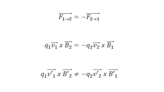
Introduction to Free Spin Precession Method (FSP) In the FSP method, the spins of polarized particles are resonantly deflected from their vertical orientation by a powerful RF-flipper a strong depolarizer that is turned on for 100 200 revolutions at a fixed frequency that is not too far off resonance. The frequency offset of the RF flipper should be small compared to its harmonic value. The free spin precession is then recorded using a Compton polarimeter. A Fourier analysis of the beats in the count rate of this polarimeter gives us the spin tune value. The first application of RF-Flipper for coherent rotation of spins by 90 degrees to the horizontal plane was carried out at VEPP-2M in an experiment comparing the magnetic moments of electrons and positrons in 1987, see: I.B. VASSERMAN et al, PHYSICS LETTERS B, Vol. 198, number 2, pp. 302-306, 1987. koop-advances in free spin precession 3
Algorithm to calculate w for the local vertical orbit bumps The effective harmonic value w of a local bump spin rotator is just a sum of ?0??- spin rotations by the M kickers or quads around the x-axis. Each kick is included in the final sum with a weight factor ??= ???0??: 1 4? ?=1 Where ?0is a spin tune, and ??is the accumulated horizontal bend angle starting from the first kick. ? ? = ?0?? ?? The half-wave -bump is the shortest. Longer spin-rotators consisting of N half-wave -bumps can provide a larger value of the depolarizer/flipper harmonic. Their strength can be calculated as the sum of a geometric progression: 1 ( ??? ?)? 1 + ??? ? ??= ?1 At Z the spin phase advance ? ? = 1.869 per one half-wave bump is small and increase of N>2 is not efficient. At W the spin phase advance ? ? = 3.297 per one half-wave bump is close to and increase of N is efficient. koop-advances in free spin precession 4
Full wave bump as a common solution for both beam energies: 45 and 80 GeV Full wave orbit bump with a kick angle amplitude ? = 1 10 5 produces the needed spin rotation at 45 GeV and almost 6 times larger at 80 GeV. 1-st kick For symmetry and with some margin I propose to install 8 such depolarizers per ring (2 in each quadrant). Also this will permit to do fast spin rotation needed in FSP method. 2-nd kick A request to beam dynamics experts: let s evaluate the DA for such local bump! Is it sufficient for the local oscillation amplitude ? = 1.1 mm ? koop-advances in free spin precession 5
Depolarizer parameters for RDP of a single bunch The desired harmonic of the depolarizer ? = 1.4 10 4. At Z two full-wave local bumps are required to limit the beam deflection by +- 1 mm. Strip Line sketch: Then at Z-energy ?????= 1 10 5- kick angle provided by each AC-dipole. ? ?? = ?? = 0.5 ????? ?? = 7.5 10 4? ? ?? = 150 ? ? , d ? ? = 2.5 ?, ? = 2 ??, ? = 3 ??, ? = 900 ? ??, ?2?????= 8100 ?, ? = 0.5 ? ? = 900 ?, ??????= 0.5 ? = ?????? a pulse. ? ? = 8100 10 ?? 320 ??? = 250 ?? - during The technical design will be developed by W. Hofle. Technically looks feasible? Parameters could be relaxed, if the distance between plates could be made smaller: ? = 1 ?? ? koop-advances in free spin precession 6
How to organize the coherent spin precession by Flipper? (as example at 45 GeV ) ????? E=45 GeV, ?0= 102.475, ?0= 0.1, ??= 0.000371 , ? = 0.002, ?0= .005, ??=0.032, ??= 1310 ????? ????? ?? ?2+ ?2 = w Spin precession in resonance frame Tracking of 400 particles with initial polarization ?0= 0.1 Flipper with w=0.002 is switched on only for 512 revolutions. In this example we assume that the flipper frequency is shifted from the resonance by a small error offset : ?0= .005. After 512 revolutions, the flipper switches off and we observe free spin precession for many thousands of revolutions. The final loss of the vertical component of the polarization is only 10% and the same bunch can be used again many times! As can be seen, the maximum deviation of the spin from the vertical initial orientation is achieved just after the first 100 revolutions. koop-advances in free spin precession 7
Fourier spectrum of the lost electrons assuming the Compton scattering asymmetry A=0.5 (at Z) E=45 GeV, ?0= 102.475, ? = 2048 ?????, ??=1000, A=0.5 Fourier transform of Poisson distribution of counts: ??=Poisson ?? 1 + ? ????? At Z polarization asymmetry of the Compton cross section relative to the longitudinal spin component could easily exceed A>0.5 and the free precession peak at =0.475 is well above the statistical noise. koop-advances in free spin precession 8
Compton polarimeter asymmetry to longitudinal polarization at Z In case of coherent spin precession we can explore large asymmetry A to the longitudinal spin component of the ICS cross-section, selecting events from two regions: / _max > 0.8 (N1) and 0.3 < / _max < 0.6 (N2). Then do FFT analysis of a signal: (N1-N2)/(N1+N2), modulated by spin precession. A Compton Polarization Asymmetry at E=45 GeV, _light=2.33 eV, _max=27.73 GeV Berestetskii, Lifshitz, Pitaevskii, Quantum Electrodynamics. N1 N2 / _max koop-advances in free spin precession 9
Compton Polarimeter: Rates koop-advances in free spin precession 10
Possible longitudinal polarimeter locations in FCC-ee koop-advances in free spin precession 11
Trajectories with different energy losses at E=45.6 GeV, place1: Lost energy electrons are intercepted by Counters 1, 2 Dipole with a negative bending field!!! ? = +0.50 ? = 0.22 -Counters N1, N2 koop-advances in free spin precession 12
Trajectories with different energy losses at E=45.6 GeV, place 2: ? = +0.50 ? = 0.22 -Counters N1, N2 koop-advances in free spin precession 13
Trajectories with different energy losses at E=45.6 GeV, place 3: ? = +0.50 ? = 0.22 - Counters N1, N2 koop-advances in free spin precession 14
The Longitudinal Compton polarimeter data analysis A longitudinal Compton polarimeter counts lost electrons scattered due to interaction with the circularly polarized laser light. The effective cross-section asymmetry to the difference in lost particle s momentum is relatively large and at Z is equal to approximately ? = 0.5. By performing a Monte Carlo simulation, I generate a Poisson distribution, assuming that the number of events is : ? = ? 1 + ? ? ?? where ? is the average number of the scattered electrons from a single bunch per turn (expected 2000 to 20000), ? is the initial polarization degree (expected 0.05 to 0.15) and ??is the longitudinal spin component of a bunch, assuming fully polarized beam in the beginning of free spin precession. I consider the beat of the counts as a polarimeter signal: ??= Statistical nature of such a signal lead to a noise in extracting of the longitudinal spin component from the polarimeter data. An example of a single run during 200 turns is presented below: ?? ? ? A more or less clear reproduction of spin precession can be seen during the first 3-5 synchrotron periods, but then the data peaks are blurred due to spin decoherence.. koop-advances in free spin precession 15
Fourier spectrum of the polarimeter data The main peak and two side frequencies (one mirror- symmetrical) are clearly visible. The argument of the largest peak can be thought of as the zeroth approximation of the precessional phase, and its frequency can be thought of as the spin tune. But can try to improve the accuracy of phase determination by calculating the correlation of the polarimeter signal with a sinusoid of a given frequency. ??????sin 2??? + ? ? ? = ?=1 then solving ? ?0=0 ?0 If such a correlation analysis of the data from all 4 polarimeters is carried out, assuming a common spin tune, then the errors in determining the phase differences between the 4 quadrants will become minimal. I performed such an analysis to find the precession phases in all 4 quadrants and determine the statistical precisions and their dependencies on input parameters such as the level of polarization or the number of scattered electrons. koop-advances in free spin precession 16
Saw-tooth model of a ring A ring with 4 IP, spaced by 900. All bending magnets have homogeneous field and parallel edges. Synchrotron radiation power: ???~?2?2. Let s assume that the damping parameter ? = ????? : ?? ??= ??2 ?(0) ? ? = 1+?? 0 ? 1 1 Here ? is a fraction of a turn, thus ? = ???? ????, ???? ????= ( ?)????. ?? 0 ?2 3 ? ? 0 ?? 1+?? 0 ?= Average energy of a particle: ? =1 1 1 ?? 0 ? ??ln 1 + ?? 0 ? ? 0 + ? 0 2 I took ????=45.62 GeV, ????= 45.581 GeV, (????+????) 2 = 45.6 GeV and ???? ????= 0.039 GeV. I placed an RF cavity at the beginning of the ring, with ???= 0.079 GV and harmonic number = 121200. The momentum compaction factor was taken as ??= 29.2 10 6. The RF phase shift accumulates according to the energy difference with the reference particle. For simplicity, the particle energy decays smoothly along the quadrant and makes quantum jumps only at their ends. In my tracking code I got the true value of the synchrotron tune ??= 0.029, see next slide. koop-advances in free spin precession 17
Synchrotron motion with saw-tooth and quantum fluctuations Quantum fluctuations occur at the beginning of each quadrant. Their relative sigma value is: = ?? ?? with ??= 3.9 10 4and ??= 1169 turns. Large oscillations do not decay exponentially, but make continuous small oscillations, finally approaching equilibrium. koop-advances in free spin precession 18
Sawtooth-Based Spin Tracking Approach I tracked the synchrotron motion of an ensemble of 1000 particles subjected to quantum fluctuations and damping. I also tracked their spins under the assumption that all they initially are oriented along the longitudinal axis. The spin rotates around the vertical axis in accordance with the energy integral for each quadrant. This integral is determined by the energy of the particle at the entrance to the quadrant (which corresponds to a quarter turn): 1 0.25 0 As a result of quantum fluctuations of SR, the spin precession phases are blurred relative to each other in a certain interval, which grows with time as the square root of the number of turns. So, decoherence of the spin ensemble occurs. But for the first few hundred turns we observe strong beating of the longitudinal spin component which occurs with the synchrotron tune (the synchrotron period is 34.5 turns). 0.25 ? 0 ?? 1 + ?? 0 ?= 1 ? = ? 0.25ln 1 + ?? 0 0.25 koop-advances in free spin precession 19
Longitudinal Compton polarimeter data analysis A longitudinal Compton polarimeter counts lost electrons scattered due to interaction with the circularly polarized laser light. The effective cross-section asymmetry to the difference in lost particle s momentum is relatively large and at Z is equal to approximately ? = 0.5. By performing a Monte Carlo simulation, I generate a Poisson distribution, assuming that the number of events scales as : ? = ? 1 + ? ? ?? where ? is the average number of the scattered electrons from a single bunch per turn (expected 2000 to 20000), ? is the initial polarization degree (expected 0.05 to 0.15) and ??is the longitudinal spin component of a bunch, assuming fully polarized beam in the beginning of free spin precession. I consider the beat of the counts as a polarimeter signal: ??= Statistical nature of such a signal lead to a noise in extracting of the longitudinal spin component from the polarimeter data. An example of a single run during 200 turns is presented below: ?? ? ? A more or less clear reproduction of spin precession can be seen during the first 3-5 synchrotron periods, but then after the data peaks are blurred due to spins decoherence. koop-advances in free spin precession 20
Fitting of phase determination errors First, I studied the dependence of phase determination accuracy on the length of the data sample. I found that for given beam parameters at Z (synchrotron tune Qs = 0.029, energy spread ??= 0.00039, damping time = 1169 turns) the optimal sample length is about 4000 turns and this dependence is not sharp. Let's look at some results with 4096 turns. For a set of input parameters ? = 0.2, ?? = 2000, ? = 0.5 I got the following sigmas (with accuracy about 10%): ??= 0.121 - for phase determination, ? ?= 0.046 - for phase difference of two quadrants. We see that the phase difference is determined approximately 3 times better than their individual values! Now another three sets: ? = 0.0625, ?? = 2000, ? = 0.5 ? = 0.0625, ?? = 4000, ? = 0.5 ? = 0.0625, ?? = 10000, ? = 0.5 ??= 0.381, ? ?= 0.163 ??= 0.285, ? ?= 0.092 ??= 0.124, ? ?= 0.069 ? Can be fitted as: ? ?~ - more or less natural scaling! ?? koop-advances in free spin precession 21
General scenario for saw tooth studies In my opinion, when FCCee launches, we should spend a few weeks or months investigating the sawtooth problem. First, of course, it is necessary to globally tune the machine and maximize the achievable level of polarization. In special sawtooth runs, we can store up to 11200 non-colliding bunches, polarize them with wigglers for several hours to a high degree (up to 40%), and then rotate spins with a flipper, bunch by bunch, and measure the free spin precession over 4000 revolutions for each bunch. The complete procedure will take several hours, since one measurement takes 1 s. Let s assume that for single bunch the attainable accuracy of the phase differences determination is about ? ?= 0.06 radians. Then, after completing the full series, we will receive a 100-fold improvement in the statistical error of phase measurement. Thus, in one beam store the achievable accuracy can reach: ? ?= 0.0006 ? = 40 keV So, about 100 series of such measurements will be enough to limit the accuracy of determining the energy difference between the 4 quadrants to the level of 4 keV. Of course, this is a very optimistic scenario - in reality, many difficulties and surprises await us. Finally, I would like to remind you that after spin rotation, the bunches are not completely depolarized, they lose only a few percent of the degree of polarization and can continue to be used again after using wigglers for few hours to restore the initial polarization level. koop-advances in free spin precession 22
Discussion of results and conclusion The free precession method allows one to obtain not only the spin tune value, but also the relative phase differences between the polarimeters installed on the ring. The phase accuracy obtained from measuring only one bunch can be of the order of 0.06 radians, which corresponds to a 4 MeV difference in the energy integrals of the two quadrants. In a series of experiments specifically devoted to studying the sawtooth shape, we hope to compress the uncertainties in the phase differences to the level of 4 keV or even better. By combining the analysis of data obtained from 4 longitudinal polarimeters and possibly from one dedicated polarimeter-energy spectrometer, we hope to obtain a real picture of the beam energy distribution between the 4 IPs and thus will determine the Ecm energies with such high accuracy. koop-advances in free spin precession 23
Thank You for Your Attention! koop-advances in free spin precession 24


")