Comprehensive Overview of Wastewater Treatment Systems and Processes
This detailed profile showcases Rajesh Bhagat's extensive academic and professional achievements in environmental engineering, focusing on wastewater treatment. It covers various treatment processes such as secondary treatment, sludge digestion, preliminary treatment, and primary treatment. References to key textbooks in the field are also provided.
- Wastewater treatment
- Environmental engineering
- Rajesh Bhagat
- Academic achievements
- Treatment processes

Download Presentation

Please find below an Image/Link to download the presentation.
The content on the website is provided AS IS for your information and personal use only. It may not be sold, licensed, or shared on other websites without obtaining consent from the author. Download presentation by click this link. If you encounter any issues during the download, it is possible that the publisher has removed the file from their server.
E N D
Presentation Transcript
Wastewater Engineering (Environmental Engg.-II) Rajesh Bhagat BE (Civil Engg) GCOE, Amravati Achievement: Selected Scientist, NEERI-CSIR, Govt. of India. MTech (Env. Engg) VNIT, Nagpur GATE Qualified Three Times. UGC - NET Qualified in First Attempt. In 2020, Recognized by SWAYAM, NPTEL & IIT: 1) Discipline Star 2) NPTEL Believer 3) NPTEL Motivated Learner Topper of PhD Course Work at UGC-HRDC, RTMNU Nagpur. Selected Junior Engineer, ZP Washim. Three Times Selected as UGC Approved Assistant Professor: 1) Assistant Professor, PCE, Nagpur. 2) Assistant Professor, Cummins College of Engg. for Women. 3) Assistant Professor, YCCE, Nagpur. Mobile No.:- 8483002277 / 8483003474 Email ID :- rajeysh7bhagat@gmail.com Website:- www.rajeysh7bhagat.wordpress.com
Unit-IV 1) Secondary Treatment: Principle of Biological Treatment, Activated sludge process & Trickling Filter. 2) Sludge Digestion & Sludge Drying Beds. 3) Methods of disposal: Disposal on land and in water stream. 4) Self-purification capacity of stream. 2
References:- 1. B.C. Punmia, Waste Water Engineering, Laxmi Publication 2. S.K. Garg, Environmental Engineering Vol II, Standard Publication 3. G.S. Birdie, Water Supply & Sanitary Engineering, Dhanpat Rai Pub Company 4. M.N. Rao & H.V.N. Rao, Air Pollution, McGraw Hill Publication. 5. M.J. Machghee, Water Supply & Sewage, McGraw Hill Publication. 6. Dr. P N Modi, Sewage Treatment & Disposal & Wastewater Engg., Rajsons Publications Pvt. Lts
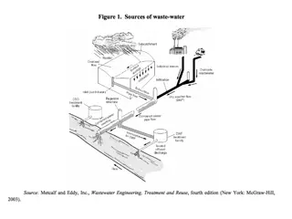
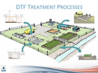
Treatment System: The type of combination used from the available unit operation and processes for treatment of a particular wastewater is known as the treatment system. Types of treatment system: 1. Preliminary Treatment 2. Primary Treatment 3. Secondary Treatment 4. Tertiary or Advanced or Final Treatment
Preliminary Treatment: To remove floating material, large size particles & heavy inorganic contents of wastewater that cause operational problems in primary & secondary treatment. It is also known as pretreatment in conventional treatment system. The preliminary Treatment includes: 1. Screen Chamber: to remove large size floating materials. 2. Grit Chamber: to remove grit & sand. 3. Skimming tank: to remove oil & grease. 4. Detritus Tank: to remove heavy organic & inorganic matter
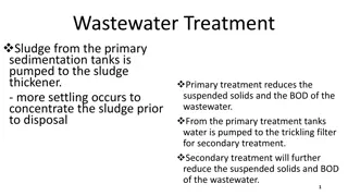
Primary Treatment: To remove settleable suspended solids. The preliminary treatment unit as well as primary settling tank are included in the primary treatment system. Primary settling tank is also known as primary clarifier. Removal of organic matter in conventional treatment takes place in two steps. The settleable suspended organic matter is removed by PST while colloidal & soluble organic fraction is removed in secondary treatment system.
Secondary Treatment: Biological Treatment To remove colloidal & soluble organic matter. Biological processes are used to remove remaining contents. Different treatment units are available: 1. ASP 2. Trickling filter 3. SST 4. RBC 5. Oxidation Pond or Waste Stabilization Pond 6. Oxidation Lagoons or Aerated lagoons 7. Oxidation ditches
Tertiary Treatment: To remove the concentration of residual impurities after secondary treatment. Used for treatment for industrial wastewater. Very expensive. Different treatment units are available: 1. Ultra and Micro Filtration 2. Ion Exchange 3. Reverse Osmosis 4. Electro dialysis 5. Adsorption 6. Chemical Precipitation 7. Nitrification / Denitrification
Biological or Secondary Wastewater Treatment:- To remove colloidal & soluble organic matter. Biological processes are used to remove remaining contents. Microorganism breakdown complex organic matter into simple and more stable substances. Sewage can remain in aerobic or anaerobic condition depending on the availability or non-availability of Oxygen. Different treatment units are available: 1. ASP 2. Trickling filter 3. SST 4. RBC 5. Oxidation Pond or Waste Stabilization Pond 6. Oxidation Lagoons or Aerated lagoons 7. Oxidation ditches
Biological Wastewater Treatment:- To remove soluble, colloidal organic matter, nutrients such as nitrogen and phosphorous from sewage. Under proper environmental conditions, the soluble organic substances of the wastewater are completely destroyed by biological oxidation; part of it is oxidized while rest is converted into biological mass, in the biological reactors. The end products of the metabolisms are either gas, liquid & the synthesized biological mass which can flocculate easily and be separated out. ACTIONS BY BACTERIA:- The colloidal & dissolved putrescible organic matters present in the sewage are absorbed within few minutes in the trickling filters and within about one hour in the ASP. Bacteria converts the organic matter into stable forms by oxidizing them. Organic matter is 10 necessary for their life.
Filter :- Filter mostly used in sewage treatment plant can be classified as 1) Intermittent Sand Filter 2) Contact Beds or Contact Filter 3) Trickling Filter. 1) Intermittent Sand Filters:- Earliest type of sewage filter, similar in construction to the slow sand filter of water treatment. Requires large area, due to which are not commonly used now days. Most suitable small area like hospitals, institutes, etc. Tank is constructed below the ground surface by excavating the earth & it is without lining on side & bottom. 2) The Contact Beds:- In ancient time contact beds were very popular in the treatment of sewage. Construction is similar to the intermittent sand filter. Water tight tank is constructed below the ground surface by excavating the earth. 3) Trickling Filters:- Used for complete treatment for domestic wastewater and as roughing 11 filter for strong industrial wastewater prior to activated sludge units. Percolating Filter or Sprinkling Filter.
Filter :- 12 Fig. 4.2 TF (16)
Filter :- 13 Fig. 4.2 TF (16)
Trickling Filter:- 1) First trickling filter adopted in 1893 in England & 1908 in US of America. . 2) Trickling filter is an attached growth process for treatment of wastewater. 3) Used for biological treatment of wastewater, which are amenable to aerobic biological processes. 4) Posses a unique capacity to handle shock loads and provide dependable performance with minimum supervision. 5) The primary sedimentation tank is provided prior to trickling filter so that the settleable solids in the sewage may not clog the filter. 6) The trickling filter is followed by secondary settling tank for removal of settleable bio- solids produced in filtration process. Fig. 4.3 TF (16)
Types of Trickling Filter:- On the basis of hydraulic & organic loading rates trickling filter are classified as: . 1) Low Rate Trickling Filter or Standard Trickling Filter or Conventional Filter 2) Intermediate Rate Trickling Filter 3) High Rate Trickling Filter 4) Super Rate Trickling Filter Construction details are same. No provision is made in low rate trickling filter for recirculation of sewage through the filter to the PST and re-passing through the filter. Recirculation ratio 0 to 1 for intermediate, 1 to 3 for high rate & 1 to 4 for super rate filter. Intermediate rate trickling filter employ rock, gravel & slag as filter media. High rate filter employ rock, slag & synthetic material such as plastic modules as filter media. Fig. 4.3 TF (16) Super rate filter employ synthetic material.
Working of Trickling Filter:- 1) The sewage is allowed to sprinkle or to trickle over a bed of course, rough & hard . material. 2) After getting trickled over the filter filtering media sewage starts percolating downward through the contact media, while moving down it is acted upon by the bacteria. 3) The dissolved & colloidal organic matter are precipitated & flocculated by the action of the bacteria & forms a gelatinous layers at the surface of the contact media. 4) The aerobic bacteria eat up this gelatinous layer & oxidize it & convert it to sulphate, phosphate, nitrate, etc. 5) The oxidation of the organic matter is carried out under aerobic conditions. 6) With the time, the gelatinous slime become thicken & heavier and move towards the bottom of the trickling filter and it is then collected through the under drainage system. 7) Slime pass out with the effluent & settle in the secondary settling tank or humus tank. Fig. 4.3 TF (16)
Construction of Trickling Filter:- 1) Essentially consists of a masonry or RCC tank which circular or rectangular in plan. . 2) Coarse aggregates of impervious nature is filled in this tank which acts as filtering media. 3) The under drainage system is provided in the bed to collect the effluent. 4) The depth of tank ranges from 1.25 to 2.5m for intermediate filter, 0.9 to 2.5 m for high rate filter, 4.5 to 12 m for super rate filter. 5) In low rate trickling filter, 1.8 to 3m. 6) In filter sufficient natural ventilation should be there to increase efficiency. 7) The most common filter media crushed stones, blast furnace slag, anthracite coal, clinker, etc are used. 8) The size of media should be between 30 mm to 100 mm.
Sloughing of The Filter:- Shredding of Biomass Layer Biological slime consisting of aerobic bacteria and other biota builds up around the . media surface. Organic material in the sewage is absorbed on the biological slime, where they are partly degraded by the biota, thus increasing the thickness of the slime. Eventually there is a scouring of the slime and fresh slime layer begins to grow on the media. This phenomenon of scouring of the slime is called sloughing of the filter.
Recirculation in High Rate Trickling Filter:- 1) Recirculation is returning portion of the treated or partly treated sewage to the treatment . process. 2) It absorbs the fluctuating in sewage flow & thus keeps the bed working. 3) It dilutes the influent with better quality waste and this making it fresh and reduces odor. 4) It maintains a uniform rate of organic and hydraulic loading. 5) It provides longer contact of the applied sewage with the bacterial film on the contact media and accelerating the biological oxidation process. 6) It increases the efficiency by reducing the BOD load generally.
Troubles at Filter Site & Their remedies:- Odour Nuisance:- . Due to anaerobic decomposition, sludging & undesirable growth. Effluent obtained from the filter can be re-circulated to continue aerobic condition. Sewage can be kept fresh by chlorination. Ponding Nuisance:- When all voids are filled up due to choking, sewage can not pass through filter & accumulates at surface in the shape of pond. By drying the media by exposing to the sun & loosening the aggregates with steel bars. By washing & flushing the filter media with high velocity jet. By applying heavy dose of chlorine after every 2 3 days. Fly Nuisance:- flies breed & developed at the sites. By chlorinating the sewage or by insecticides.
SN Parameter Standard Rate High Rate Trickling Filter Trickling Filter 1 Operation Cost More Less 2 Space Required More Less 3 Flexible Less More 4 Skilled Supervision Required Less More 5 Organic Loading Rate, Kg of BOD 5 per 900 to 2200 6000 to 18000 ha-m per day 6 Depth of Filter 1.8 to 3.0 0.9 to 2.5m 7 Size of Filter Media 30 to 80 mm 30 to 60 mm 8 Hydraulic Loading Rate, ML/ha/day 22 to 44 110 to 330 9 Recirculation Not Provided Provided 10 Effluent Highly Stabilized Not Highly Stabilized 11 Interval Dosing / sloughing Intermittent Continuous 5 minutes 15 Seconds
Activated Sludge Process:- 1) Aerobic biological treatment system. 2) Units of process are aeration tank, secondary settling tank, sludge return, etc. 3) Wastewater is aerated in an aeration tank for a period of few hours. Microorganisms stabilize the organic matter. 4) After aeration, sewage is taken to the secondary settling tank where separation of biological mass (solids) 5) Oxidation reaction is the main mechanism of BOD removal in the activated sludge process. 6) Activated sludge is the sludge obtained by settling sewage (Solids) in presence of an abundant oxygen. Biologically active & contains great numbers of aerobic bacteria & other microorganism which have an unusual property to oxidize the organic matter. (96 % moisture content) 7) Activated sludge is re-circulated before aeration tank. Fig. 4.1 ASP (16) 22
23 Figure of Activated Sludge Process
Activated Sludge Process: 1) The biomass generated in the aeration tank is generally flocculent. 2) Biomass is separated in a SST & is recycled partially to the aeration tank. 3) The mixture of recycled sludge & sewage in the aeration tank is referred as mixed liquor. 4) Aeration units are main units of ASP, to supply oxygen to the sewage to keep the reactor content aerobic & to mix up the return sludge & wastewater thoroughly. 5) Once the required concentration of microorganism in the mixed liquor has been reached its further increase is prevented by the regulating quantity of sludge recycled. 6) Detention period between 6 to 8 hours. 7) The volume of aeration tank is also decided by considering the return sludge, which is about 25 to 50% ofthe wastewater volume. 8) Normally liquid depth should be between 3 and 4.5 m. (F.B. = 0.3 to 0.6 m) 9) The mode of air supply in aeration tank can be either diffused air aeration, by supplementing compressed air from tank bottom, or by mechanical aerators provided at surface.
Modifications in ASP:- Several modifications to the conventional system have been developed to meet specific treatment objectives. Major modification are follows:- 1) Tapered aeration or Controlled aeration: Oxygen demand is not uniform throughout in tank, it is max. near inlet & minimum near the outlet. Therefore attempts made to supply air to match oxygen demand along the length of the tank. 2) Step aeration: Sewage is introduced at several points along the tank length which produces more uniform oxygen demand throughout. 3) Contact stabilization: provides for re-aeration of return activated sludge separately from the final clarifier, which allows a smaller aeration or contact tank. 4) Completely mixed: It is achieved by distributing the sewage and the return sludge uniformly along one side & withdrawing the aerated sewage uniformly along the opposite side of tank. Detention time is smaller & F/M ratio is more. 5) Extended Aeration process operates at a low organic load producing lesser quantity of well stabilized sludge. Detention time is more & F/M ratio is lower.
Modifications in ASP:- 6) Two stage aeration: In two stage aeration the sewage is allowed to flow in a pair of aeration & sedimentation units. 7) Modified Aeration: In this method less quantity of returned sludge, shorter detention period & lesser amounts of compressed air is used therefore it is called high rate treatment. Classification of Aeration Units:- Diffuser Air Units Mechanical Aeration Units Combined Mechanical & Diffuser Air Units
Conventional ASP: Completely Mixed:
Step Aeration: Contact Stabilization:
Sludge Digestion:- 1) Decomposition of complex organic substances present in sludge into simpler stable compounds by bio-chemical reaction brought about by the anaerobic bacteria. 2) Volume of sludge is reduced by 60 to 75% due to solid are converted into liquid & gases. 3) Gases can be used as fuel & digested sludge has very good fertilizing value. 4) Sludge is broken up into 3 parts: digested sludge, gases & Supernatant liquor. 5) The tank in which sludge digestion is carried out is a called sludge digestion tank. 6) Three stages are occurred in the biological process of sludge digestion. A. Acidification: Sludge begins to decompose anaerobically, bacteria attacks easily on available food substances such as carbohydrates & soluble nitrogenous compounds. Intensive acids are produced. B. Liquification: Organic acids & nitrogenous compounds are liquified ie transformed from large solids particles to either a soluble or finely or finely dissolved form. pH rises a little hence this process is also called acid regression. C. Gasification: Due to breaking proteins & organic acids, large volume of methane & small of volume of CO2 are evolved.
. Sludge Digestion:-
Anaerobic Digestion Process:- (Sludge Digestion Tank) The purpose of the anaerobic process is to convert sludge to end products of liquid and gases while producing as little biomass as possible. The process is much more economical than aerobic digestion. The process has now been described by the following four steps: 1. Hydrolysis: Large polymers are broken down by enzymes and converted into simple soluble organic compounds. 2. Fermentation (Acidogenesis): Soluble organic matter is converted to acetic acid by acid former ie acidogenic bacteria. Acidogenic fermentations are most important. Volatile fatty acids are also produced along with carbon dioxide and hydrogen. (Volatile Organic acid formation) 3. Acetogenesis: Breakdown of volatile acids to acetate and hydrogen. (Acetate Formation) 4. Methanogenesis: Acetate, formaldehyde, hydrogen and carbon dioxide are converted to methane and water. (Methane Formation)
Sludge Thickener:- To reduce volume to handled sludge in better way in sludge digester, sludge thickener is provided. There are three types sludge thickener: 1) Gravity Thickener 2) Air Floating 3) Centrifugation
Sludge Drying Bed:- 1) Sludge drying beds are commonly used in small wastewater treatment plants to dewater the sludge prior to final disposal. 2) Drying of the digested sludge is made on open beds of land, these open beds are called as SDB. 3) Two mechanisms are involved in the process, such as filtration of water through the sand, and evaporation of water from sludge surface. 4) A typical sludge drying bed consist of 15 to 30 cm of coarse sand layer underlain by approximately 20 to 45 cm of grade gravel ranging in size from 0.6 to 4 cm. 5) Open jointed tubes of 10 to 15 cm diameter spaced at 2.5 to 6 cm are laid in the gravel to provide drainage for liquid passing through the bed. 6) Sludge is applied to the drying bed in layer of 20 to 30 cm, depending upon local climatic conditions the sludge is allowed to dry for two to four weeks. 7) Enclosing drying beds with glass can improve the performance of the dewatering process, particularly in cold or wet climates.
Affecting Self Purification of Stream:- 1) When sewage is discharged into a natural stream or river, the organic matter present in the sewage gets oxidized by bacteria & converted to simple, inoffensive, stable substances. 2) Dissolved oxygen (DO) content of the river or stream water is utilized. Due to this deficiency of dissolved oxygen is created in river or stream water. 3) The deficiency of dissolved oxygen thus created in river or stream water is filled up by the absorption of atmospheric oxygen. Thus dissolved oxygen of river water is consumed by sewage discharged into it & at the same time it is replenished by the atmosphere. 4) This phenomena which occurs in all natural streams or rivers is known as self-purification of natural streams or rivers. 5) It is thus seen that natural streams, polluted by sewage, are purified in natural course by the phenomenon of self-purification. 6) The rate of self-purification depends on various factors such as rate of re-aeration, type of organic matter present in sewage, temperature, velocity of flow, presence of available oxygen in receiving waters, sedimentation, etc.
Factors Affecting Self Purification of Stream:- 1) Dilution: When sufficient dilution water is available in the receiving water body, where the wastewater is discharged, the DO level in the receiving stream may not reach to zero or critical DO due to availability of sufficient DO initially in the river water before receiving discharge of wastewater. 2) Current: When strong water current is available, the discharged wastewater will be thoroughly mixed with stream water preventing deposition of solids. In small current, the solid matter from the wastewater will get deposited at the bed following decomposition and reduction in DO. 3) Temperature: The quantity of DO available in stream water is more in cold temperature than in hot temperature. Also, as the activity of microorganisms is more at the higher temperature, hence, the self- purification will take less time at hot temperature than in winter. 4) Sunlight: Algae produces oxygen in presence of sunlight due to photosynthesis. Therefore, sunlight helps in purification of stream by adding oxygen through photosynthesis. 5) Rate of Oxidation: Due to oxidation of organic matter discharged in the river DO depletion occurs. This rate is faster at higher temperature and low at lower temperature. The rate of oxidation of organic matter depends on the chemical composition of organic matter.
Different zones of pollution in river stream:- (Oxygen Sag Curve) A river stream undergoing self purification can be divided into following four zones of pollution. 1) Zone of degradation: This zone exists upto a certain length beyond the point just below the sewage out fall. Water becomes dark & turbid along with foundation of sludge deposits at the bottom. 2) Zone of active decomposition: This highly polluted zone. Water becomes grayish & much darker. DO falls down to almost zero. 3) Zone of recovery: stream rover from its degradation condition. Water becomes clear & algae reappears. DO level increases. 4) Zone of cleaner water: River comes to original level. DO level reaches to saturation level ^ usual aquatic life prevails.
Deoxygenation and Reoxygenation Curve: 1) When wastewater is discharged in to the stream, the DO level in the stream goes on depleting. This depletion of DO content is known as deoxygenation. 2) The rate of deoxygenation depends upon the amount of organic matter remaining (Lt), to be oxidized at any time t, as well as temperature (T) at which reaction occurs. 3) The ordinates below the deoxygenation curve (Figure) indicate the oxygen remaining in the natural stream after satisfying the bio-chemical demand of oxygen. 4) When the DO content of the stream is gradually consumed due to BOD load, atmosphere supplies oxygen continuously to the water, through the process of re-aeration or reoxygenation, i.e., along with deoxygenation, re-aeration is continuous process. The oxygen sag or oxygen deficit in the stream at any point of time during self purification process is the difference between the saturation DO content and actual DO content at that time. Oxygen deficit, D = Saturation DO Actual DO
The rate of reoxygenation depends upon: 1) Depth of water in the stream: more for shallow depth. 2) Velocity of flow in the stream: less for stagnant water. 3) Oxygen deficit below saturation DO: since solubility rate depends on difference between saturation concentration and existing concentration of DO. 4) Temperature of water: solubility is lower at higher temperature and also saturation concentration is less at higher temperature. 49
Disposal Methods of Wastewater: 1) Into Surface water. 2) On Land. 3) Others: Reuse for farming, gardening, etc.
")


")
")