Understanding Network Topologies: Bus vs Ring
Explore the world of network topologies with a focus on Bus and Ring configurations. Learn about their features, advantages, and disadvantages, helping you understand the layout and connectivity options in computer networks.
Download Presentation
Please find below an Image/Link to download the presentation.
The content on the website is provided AS IS for your information and personal use only. It may not be sold, licensed, or shared on other websites without obtaining consent from the author. Download presentation by click this link. If you encounter any issues during the download, it is possible that the publisher has removed the file from their server.

Presentation Transcript
Data Communication & Data Communication & Networks Networks UNIT#7 UNIT#7
Network Topology Network Topology A Network Topology is the arrangement with which computer systems or network devices are connected to each other. In networking, topology refers to the layout of a computer network. Topologies may define both physical and logical aspect of the network. Both logical and physical topologies could be same or different in a same network. Physical topology means the placement of the elements of the network, including the location of the devices or the layout of the cables.
Types of Topologies Types of Topologies
Bus Topology Bus Topology Bus topology is a network type in which every computer and network device is connected to single cable. When it has exactly two endpoints, then it is called Linear Bus topology.
Features of Bus Topology 1.It transmits data only in one direction. 2.Every device is connected to a single cable
Advantages of Bus Topology 1.It is cost effective. 2.Cable required is least compared to other network topology. 3.Used in small networks. 4.It is easy to understand. 5.Easy to expand joining two cables together.
Disadvantages of Bus Topology 1.Cables fails then whole network fails. 2.If network traffic is heavy or nodes are more the performance of the network decreases. 3.Cable has a limited length. 4.It is slower than the ring topology.
Ring Topology Ring Topology It is called ring topology because it forms a ring as each computer is connected to another computer, with the last one connected to the first. Exactly two neighbors for each device.
Features of Ring Topology 1.A number of repeaters are used for Ring topology with large number of nodes, because if someone wants to send some data to the last node in the ring topology with 100 nodes, then the data will have to pass through 99 nodes to reach the 100th node. Hence to prevent data loss repeaters are used in the network. 2.The transmission is unidirectional, but it can be made bidirectional by having 2 connections between each Network Node, it is called Dual Ring Topology. 3.In Dual Ring Topology, two ring networks are formed, and data flow is in opposite direction in them. Also, if one ring fails, the second ring can act as a backup, to keep the network up. 4.Data is transferred in a sequential manner that is bit by bit. Data transmitted, has to pass through each node of the network, till the destination node.
Advantage & Disadvantage Advantage & Disadvantage Advantages of Ring Topology 1.Transmitting network is not affected by high traffic or by adding more nodes, as only the nodes having tokens can transmit data. 2.Cheap to install and expand Disadvantages of Ring Topology 1.Troubleshooting is difficult in ring topology. 2.Adding or deleting the computers disturbs the network activity. 3.Failure of one computer disturbs the whole network.
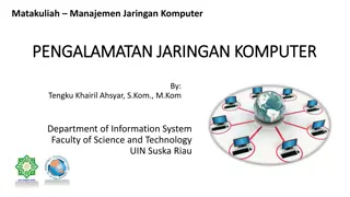
Star Topology Star Topology In this type of topology all the computers are connected to a single hub through a cable. This hub is the central node and all others nodes are connected to the central node.
Features of Star Topology 1.Every node has its own dedicated connection to the hub. 2.Hub acts as a repeater for data flow. 3.Can be used with twisted pair, Optical Fibre or coaxial cable.
Advantage & Disadvantage Advantage & Disadvantage Advantages of Star Topology 1.Fast performance with few nodes and low network traffic. 2.Hub can be upgraded easily. 3.Easy to troubleshoot. 4.Easy to setup and modify. 5.Only that node is affected which has failed, rest of the nodes can work smoothly. Disadvantages of Star Topology 1.Cost of installation is high. 2.Expensive to use. 3.If the hub fails then the whole network is stopped because all the nodes depend on the hub. 4.Performance is based on the hub that is it depends on its capacity
Mesh Topology Mesh Topology A mesh topology is a network setup where each computer and network device is interconnected with one another. This topology setup allows for most transmissions to be distributed even if one of the connections goes down. It is a topology commonly used for wireless networks.
Advantage Advantage
Types of Network Types of Network LAN WAN MAN
Properties of LAN Properties of LAN
MAN MAN
WAN WAN
Communication protocol Communication protocol
Functions of communication protocol Functions of communication protocol
OSI Model OSI Model
Physical Layer The physical layer helps you to define the electrical and physical specifications of the data connection. This level establishes the relationship between a device and a physical transmission medium. The physical layer is not concerned with protocols or other such higher-layer items. Examples of hardware in the physical layer are network adapters, ethernet, repeaters, networking hubs, etc.
Data Link Layer: Data link layer corrects errors which can occur atthephysical layer. The layer allows you to define the protocol to establish and terminates a connection between two connectednetwork devices. It is IP address understandable layer, which helps you to define logical addressing so that any endpointshould be identified. Thelayer also helps youimplement routingofpackets through a network. It helps you to define the best path, which allows you to take data from the source to the destination. The datalinklayerissubdividedintotwotypesofsublayers: Media Access Control (MAC) layer- It is responsible for controlling how device in a network gain access tomedium andpermits totransmit data. Logical link control layer- This layer is responsible for identity and encapsulating network-layer protocolsand allows youtofindtheerror.
Transport Layer: The transport layer builds on the network layer to provide data transport from a process on a source machine to a process on a destination machine. It is hosted using single or multiple networks, and also maintains the quality of service functions. It determines how much data should be sent where and at what rate. This layer builds on the message which are received from the application layer. It helps ensure that data units are delivered error-free and in sequence. Transport layer helps you to control the reliability of a link through flow control, error control, and segmentation or desegmentation. The transport layer also offers an acknowledgment of the successful data transmission and sends the next data in case no errors occurred. TCP is the best-known example of the transport layer.
Network Layer: The network layer provides the functional and procedural means of transferring variable length data sequences from one node to another connected in "different networks". Message delivery at the network layer does not give any guaranteed to be reliable network layer protocol. Layer-management protocols that belong to the network layer are: 1.routing protocols 2.multicast group management 3.network-layer address assignment.
Session Layer Session Layer controls the dialogues between computers. It helps you to establish starting and terminating the connections between the local and remote application. This layer request for a logical connection which should be established on end user's requirement. This layer handles all the important log-on or password validation. Session layer offers services like dialog discipline, which can be duplex or half-duplex. It is mostly implemented in application environments that use remote procedure calls. Important function of Session Layer: It establishes, maintains, and ends a session. Session layer enables two systems to enter into a dialog It also allows a process to add a checkpoint to steam of data.
Presentation Layer Presentation layer allows you to define the form in which the data is to exchange between the two communicating entities. It also helps you to handles data compression and data encryption. This layer transforms data into the form which is accepted by the application. It also formats and encrypts data which should be sent across all the networks. This layer is also known as a syntax layer. The function of Presentation Layers: Character code translation fromASCII to EBCDIC. Data compression: Allows to reduce the number of bits that needs to be transmitted on the network. Data encryption: Helps you to encrypt data for security purposes for example, password encryption. It provides a user interface and support for services like email and file transfer.
Application Layer Application layer interacts with an application program, which is the highest level of OSI model. The application layer is the OSI layer, which is closest to the end-user. It means OSI application layer allows users to interact with other software application. Application layer interacts with software applications to implement a communicating component. The interpretation of data by the application program is always outside the scope of the OSI model. Example of the application layer is an application such as file transfer, email, remote login, etc. The function of theApplication Layers are: Application-layer helps you to identify communication partners, determining resource availability, and synchronizing communication. It allows users to log on to a remote host This layer provides various e-mail services
Layer Layer 7 Name Application Function To allow access to network resources. To translate, encrypt and compress data. To establish, manage, and terminate the session The transport layer builds on the network layer to provide data transport from a process on a source machine to a process on a destination machine. Protocols SMTP, HTTP, FTP, POP3, SNMP MPEG, ASCH, SSL, TLS Layer 6 Presentation Layer 5 Session NetBIOS, SAP Layer 4 Transport TCP, UDP
Layer 3 Network To provide internetworking To move packets from source to destination To organize bits into frames To provide hop- to-hop delivery To transmit bits over a medium To provide mechanical and electrical specifications IPV5, IPV6, ICMP, IPSEC, ARP, MPLS. Layer 2 Data Link RAPA, PPP, Frame Relay, ATM, Fiber Cable, etc. RS232, 100BaseTX, ISDN, 11. Layer 1 Physical
Network interface Card Network interface Card
Multimedia Multimedia UNIT#8
Introduction to multimedia Introduction to multimedia
Introduction to multimedia Introduction to multimedia
Introduction to multimedia Introduction to multimedia
Multimedia components Multimedia components
Text Text
Text Text
Graphics Graphics
Properties of Graphics Properties of Graphics
Animation Animation
Characteristics of Multimedia Characteristics of Multimedia
Video Video
Audio Audio
Multimedia Applications Multimedia Applications A Multimedia Application is an Application which uses a collection of multiple media sources e.g. text, graphics, images, sound/audio, animation and/or video. Hypermedia can be considered as one of the multimedia applications.