Understanding Object-Oriented Software Engineering Principles

Object Oriented Software
Engineering
L2 3-2-2020
Inheritance
Inheritance
– the concept wherein methods
and/or attributes defined in an object class can be
inherited or reused by another object class.
Inheritance (cont.)
Generalization/Specialization, Supertype, and
Subtype
Generalization/specialization
– technique wherein attributes and behaviors
common to several types of object classes are grouped (or abstracted) into their
own class, called a
supertype
.
Supertype
– an entity that contains attributes and behaviors that are common to
one or more class subtypes. Also referred to as
abstract
or
parent
class.
Subtype
– an object class that inherits attributes and behaviors from a supertype
class and may contain other attributes and behaviors unique to it. Also referred to
as a
child
class and, if it exists at the lowest level of the inheritance hierarchy, as
concrete
class.
UML Representation of
Generalization/Specialization
Generalization/Specialization Hierarchies
Object/Class Relationships
Object/class
relationship
– a natural business
association that exists between one or more objects
and classes.
UML Multiplicity Notations
Multiplicity
– the minimum and maximum number of occurrences
of one object/class for a single occurrence of the related
object/class.
Aggregation
Aggregation
– a relationship in
which one larger “whole” class
contains one or more smaller
“parts” classes. Conversely, a smaller
“part” class is part of a “whole”
larger class
•
In UML 2.0 the notation for
aggregation has been dropped
•
Aggregation
•
“
Part-whole
” or “a-part-of” relationship
•
Used for components and assembly
•
Existence of a part depends on existence of whole
•
Tightly coupled form of association
Aggregation semantics (properties):
•
Transitivity
•
If A is part of B and B is part of C, then A is part of C
•
Antisymmetric
•
If A is part of B, then B is not part of A
•
Propagation of properties
•
e.g. location of a door handle is obtained from the
door; door obtains its properties from the car, …
D
o
c
u
m
e
n
t
P
a
r
a
g
r
a
p
h
S
e
n
t
e
n
c
e
Composition
Composition
– an aggregation
relationship in which the
“whole” is responsible for the
creation and destruction of its
“parts.” If the “whole” were to
die, the “part” would die with
it.
Messages
Message
– communication that occurs when one
object invokes another object’s method (behavior)
to request information or some action
Polymorphism
Polymorphism
– the concept that
different objects can respond to the
same message in different ways.
Override
– a technique whereby a
subclass (subtype) uses an attribute or
behavior of its own instead of an
attribute or behavior inherited from the
class (supertype).
UML 2.0 Diagrams
UML 2.0 Diagrams (cont.)
UML Diagram Hierarchy
3 Models
•
Object Model
•
Dynamic Model
•
Functional Model
The Process of Object Modeling
1.
Modeling the functions of the system.
2.
Finding and identifying the business objects.
3.
Organizing the objects and identifying their relationships.
Construction the Analysis
Use-Case Model
System analysis use case
– a use case that documents the
interaction between the system user and the system. It is
highly detailed in describing what is required but is free of
most implementation details and constraints.
1.
Identify, define, and document new actors.
2.
Identify, define, and document new use cases.
3.
Identify any reuse possibilities.
4.
Refine the use-case model diagram (if necessary).
5.
Document system analysis use-case narratives.
Use-Case Model Diagram
Use-Case
Narrative
Abstract Use-Case Narrative
Modeling Use-Case Activities
Activity diagram
– a
diagram that can be used
to graphically depict the
flow of a business
process, the steps of a
use case, or the logic of
an object behavior
(method).
Activity Diagram Notations
1.
Initial node
- solid circle
representing the start
of the process.
2.
Actions
– rounded
rectangles representing
individual steps. The
sequence of actions
make up the total activity
shown by the diagram.
3.
Flow
- arrows on the
diagram indicating the
progression through the
actions. Most flows do not
need words to identify them unless coming out of decisions.
4.
Decision
- diamond shapes with one flow coming in and two or more flows
going out. The flows coming out are marked to indicate the conditions.
5.
Merge
- diamond shapes with multiple flows coming in and one flow going
out. This combines flows previously separated by decisions. Processing
continues with any one flow coming into the merge.
Activity Diagram Notations (cont.)
6.
Fork
– a black bar
with one flow
coming in and two
or more flows going
out. Actions on
parallel flows
beneath the fork
can occur in any
order or
concurrently.
7.
Join
– a black bar with two or more flows coming in
and one flow going out, noting the end of concurrent
processing. All actions coming into the join must be
completed before processing continues.
8.
Activity final
– the solid circle inside the hollow circle
representing the end of the process.
Activity Diagram with Partitions
9.
Subactivity indicator
– the rake
symbol in an action indicates that
this action is broken out in
another separate activity diagram.
This helps you keep the activity
diagram from becoming overly
complex.
10.
Connector
– A letter inside a
circle gives you another tool for
managing complexity. A flow
coming into a connector jumps to
the flow coming out of a
connector with a matching letter.
Drawing System Sequence Diagrams
System sequence diagram
- a diagram that depicts the interaction
between an actor and the system for a use case scenario.
•
helps identify high-level messages that enter and exit the system
System Sequence Diagram Notations
1.
Actor
- the initiating actor of the
use case is shown with the use
case actor symbol.
2.
System
– the box indicates the
system as a "black box" or as a
whole. The colon (:) is standard
sequence diagram notation to
indicate a running "instance" of
the system.
3.
Lifelines
– the dashed vertical
lines extending downward from
the actor and system symbols,
which indicate the life of the
sequence.
4.
Activation bars
– the bars set
over the lifelines indicate period
of time when participant is active
in the interaction.
System Sequence Diagram
Notations (cont.)
5.
Input messages
- horizontal
arrows from actor to system
indicate the message inputs.
UML convention for messages
is to begin the first word with
a lowercase letter and add
additional words with initial
uppercase letter and no
space. In parentheses include
parameters, following same
naming convention and
separated with commas.
6.
Output messages –
horizontal
arrows from system to actor
shown as dashed lines. Since
they are web forms, reports,
e-mails, etc. these messages
do not need to use the
standard notation.
System Sequence Diagram
Notations (cont.)
7.
Receiver Actor
– other actors or
external systems
that receive
messages from
the system can
be included.
8.
Frame
– a box
can enclose
one or more
messages to
divide off a fragment
of the sequence. These can show loops, alternate fragments, or optional
(opt) steps. For an optional fragment the condition shown in square brackets
indicates the conditions under which the steps will be performed.
Explore the concepts of inheritance, generalization/specialization, UML representation, object/class relationships, multiplicity notations, and aggregation in object-oriented software engineering. Learn how methods and attributes can be inherited, grouped, and reused among classes, and understand the relationships and hierarchies established through these principles.

Download Presentation

Please find below an Image/Link to download the presentation.
The content on the website is provided AS IS for your information and personal use only. It may not be sold, licensed, or shared on other websites without obtaining consent from the author. Download presentation by click this link. If you encounter any issues during the download, it is possible that the publisher has removed the file from their server.
E N D
Presentation Transcript
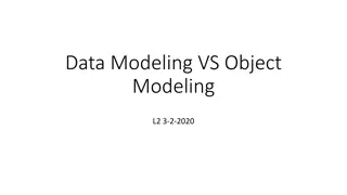
Object Oriented Software Engineering L2 3-2-2020
Inheritance Inheritance the concept wherein methods and/or attributes defined in an object class can be inherited or reused by another object class.
Generalization/Specialization, Supertype, and Subtype Generalization/specialization technique wherein attributes and behaviors common to several types of object classes are grouped (or abstracted) into their own class, called a supertype. Supertype an entity that contains attributes and behaviors that are common to one or more class subtypes. Also referred to as abstract or parent class. Subtype an object class that inherits attributes and behaviors from a supertype class and may contain other attributes and behaviors unique to it. Also referred to as a child class and, if it exists at the lowest level of the inheritance hierarchy, as concrete class.
UML Representation of Generalization/Specialization
Object/Class Relationships Object/class relationship a natural business association that exists between one or more objects and classes.
UML Multiplicity Notations Multiplicity the minimum and maximum number of occurrences of one object/class for a single occurrence of the related object/class.
Aggregation Aggregation a relationship in which one larger whole class contains one or more smaller parts classes. Conversely, a smaller part class is part of a whole larger class In UML 2.0 the notation for aggregation has been dropped
Aggregation Part-whole or a-part-of relationship Used for components and assembly Existence of a part depends on existence of whole Tightly coupled form of association Aggregation semantics (properties): Transitivity If A is part of B and B is part of C, then A is part of C Antisymmetric If A is part of B, then B is not part of A Propagation of properties e.g. location of a door handle is obtained from the door; door obtains its properties from the car, Document Paragraph Sentence
Composition Composition an aggregation relationship in which the whole is responsible for the creation and destruction of its parts. If the whole were to die, the part would die with it.
Messages Message communication that occurs when one object invokes another object s method (behavior) to request information or some action
Polymorphism Polymorphism the concept that different objects can respond to the same message in different ways. Override a technique whereby a subclass (subtype) uses an attribute or behavior of its own instead of an attribute or behavior inherited from the class (supertype).
UML 2.0 Diagrams Diagram Use Case Description Depicts interactions between the system and external systems and users. In other words it graphically describes who will use the system and in what ways the user expects to interact with the system. The use-case narrative is used in addition to textually describe the sequence of steps of each interaction. Depicts sequential flow of activities of a use case or business process. It can also be used to model logic with the system. Depicts the system's object structure. It shows object classes that the system is composed of as well as the relationships between those object classes. Similar to a class diagram, but instead of depicting object classes, it models actual object instances with current attribute values. The object diagram provides the developer with a "snapshot" of the system's object at one point in time. Models how events can change the state of an object over its lifetime, showing both the various states that an object can assume and the transitions between those states. Decomposes internal structure of class, component, or use case. Activity Class Object State Machine Composite Structure
UML 2.0 Diagrams (cont.) Diagram Sequence Description Graphically depicts how objects interact with each other via messages in the execution of a use case or operation. It illustrates how messages are sent and received between objects and in what sequence. (Collaboration diagram in UML 1.X) Depicts interaction of objects via messages. While a sequence diagram focuses on the timing or sequence of messages, a communication diagram focuses on the structural organization of objects in a network format. Combines features of sequence and activity diagrams to show how objects interact within each activity of a use case. Another interaction diagram that focuses on timing constraints in the changing state of a single object or group of objects. Especially useful when designing embedded software for devices. Depicts the organization of programming code divided into components and how the components interact. Depicts the configuration of software components within the physical architecture of the system's hardware "nodes." Depicts how classes or other UML constructs are organized into packages (corresponding to Java packages or C++ and .NET namespaces) and the dependencies of those packages. Communication Interaction Overview Timing Component Deployment Package
3 Models Object Model Dynamic Model Functional Model
The Process of Object Modeling 1. Modeling the functions of the system. 2. Finding and identifying the business objects. 3. Organizing the objects and identifying their relationships.
Construction the Analysis Use-Case Model System analysis use case a use case that documents the interaction between the system user and the system. It is highly detailed in describing what is required but is free of most implementation details and constraints. 1. Identify, define, and document new actors. 2. Identify, define, and document new use cases. 3. Identify any reuse possibilities. 4. Refine the use-case model diagram (if necessary). 5. Document system analysis use-case narratives.
Use-Case Narrative
Modeling Use-Case Activities Activity diagram a diagram that can be used to graphically depict the flow of a business process, the steps of a use case, or the logic of an object behavior (method).
Activity Diagram Notations 1.Initial node - solid circle representing the start of the process. 2.Actions rounded rectangles representing individual steps. The sequence of actions make up the total activity shown by the diagram. 3.Flow - arrows on the diagram indicating the progression through the actions. Most flows do not need words to identify them unless coming out of decisions. 4.Decision - diamond shapes with one flow coming in and two or more flows going out. The flows coming out are marked to indicate the conditions. 5.Merge - diamond shapes with multiple flows coming in and one flow going out. This combines flows previously separated by decisions. Processing continues with any one flow coming into the merge.
Activity Diagram Notations (cont.) 6.Fork a black bar with one flow coming in and two or more flows going out. Actions on parallel flows beneath the fork can occur in any order or concurrently. 7.Join a black bar with two or more flows coming in and one flow going out, noting the end of concurrent processing. All actions coming into the join must be completed before processing continues. 8.Activity final the solid circle inside the hollow circle representing the end of the process.
Activity Diagram with Partitions 9.Subactivity indicator the rake symbol in an action indicates that this action is broken out in another separate activity diagram. This helps you keep the activity diagram from becoming overly complex. 10.Connector A letter inside a circle gives you another tool for managing complexity. A flow coming into a connector jumps to the flow coming out of a connector with a matching letter.
Drawing System Sequence Diagrams System sequence diagram - a diagram that depicts the interaction between an actor and the system for a use case scenario. helps identify high-level messages that enter and exit the system
System Sequence Diagram Notations 1. Actor - the initiating actor of the use case is shown with the use case actor symbol. 2. System the box indicates the system as a "black box" or as a whole. The colon (:) is standard sequence diagram notation to indicate a running "instance" of the system. 3. Lifelines the dashed vertical lines extending downward from the actor and system symbols, which indicate the life of the sequence. 4. Activation bars the bars set over the lifelines indicate period of time when participant is active in the interaction.
System Sequence Diagram Notations (cont.) 5. Input messages - horizontal arrows from actor to system indicate the message inputs. UML convention for messages is to begin the first word with a lowercase letter and add additional words with initial uppercase letter and no space. In parentheses include parameters, following same naming convention and separated with commas. 6. Output messages horizontal arrows from system to actor shown as dashed lines. Since they are web forms, reports, e-mails, etc. these messages do not need to use the standard notation.
System Sequence Diagram Notations (cont.) 7. Receiver Actor other actors or external systems that receive messages from the system can be included. 8. Frame a box can enclose one or more messages to divide off a fragment of the sequence. These can show loops, alternate fragments, or optional (opt) steps. For an optional fragment the condition shown in square brackets indicates the conditions under which the steps will be performed.


")


")


")