Performance Evaluation of Coordinated Beamforming with Parameterized Spatial Reuse in IEEE 802.11be

The document discusses the performance evaluation of coordinated beamforming with parameterized spatial reuse (PSR) in IEEE 802.11be. It explores the practical operation of the 802.11ax PSR framework with null steering and the key implementation benefits, emphasizing unsynchronized operation and adaptability to null steering impairments.
- Performance Evaluation
- Coordinated Beamforming
- Parameterized Spatial Reuse
- IEEE 802.11be
- Null Steering

Uploaded on Oct 03, 2024 | 0 Views
Download Presentation

Please find below an Image/Link to download the presentation.
The content on the website is provided AS IS for your information and personal use only. It may not be sold, licensed, or shared on other websites without obtaining consent from the author. Download presentation by click this link. If you encounter any issues during the download, it is possible that the publisher has removed the file from their server.
E N D
Presentation Transcript
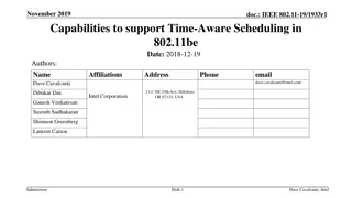
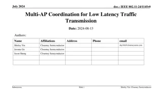
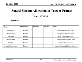
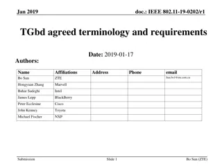
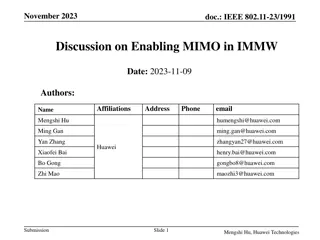
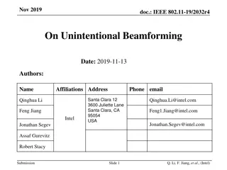
January 2020 doc.: IEEE 802.11-20/0091r2 Performance of parameterized spatial reuse (PSR) with coordinated beamforming/null steering for 802.11be Date: 2020-01-10 Authors: Name Affiliation Address Phone Email Adrian Garcia-Rodriguez David Lopez-Perez Lorenzo Galati Giordano adrian.garcia_rodriguez@ nokia-bell-labs.com Nokia Olli Alanen Mika Kasslin Eloise de Carvalho Rodrigues Enrico Rantala Submission Slide 1 Adrian Garcia-Rodriguez, Nokia
January 2020 doc.: IEEE 802.11-20/0091r2 Introduction As shown in [19/1594r2], the 802.11ax parameterized spatial reuse (PSR)* framework provides a good basis for coordinated beamforming/null steering, since it allows APs to altruistically but coordinately share an uplink transmission opportunity (TXOP) with other inter-BSS devices The performance gains of synchronous coordinated beamforming systems have been demonstrated in [19/0772r1] and [19/1212r2] In this contribution, we briefly review the PSR framework with coordinated beamforming/null steering of [19/1594r2], and * evaluate the performance of such scheme *referred to as spatial reuse parameter (SRP) in drafts D1.0 D5.1 Submission Slide 2 Adrian Garcia-Rodriguez, Nokia
January 2020 doc.: IEEE 802.11-20/0091r2 802.11ax PSR framework with null steering: Practical operation Standard PSR framework + coordinated null steering (see [19/1594r2]) Phase 1 Coord. Phase 2 Implicit CSI acquisition Phase 3 Coordinated inter-AP DATA TX & ACK with nulls Data transmission Null steering TF advertises spatial reuse opportunity AP1 nulls STA21 TF ACK UL data reception CRequest NDPA TF NDP NDP donor AP1 BSS1 NDP UL data NDP STA11 NDP UL data STA12 AP2 nulls STAs 11 and 12 ACK TF UL data reception NDP CResponse AP2 Contention BSS2 NDP UL data NDP STA21 t STA21 measures power, and identifies a spatial reuse opportunity (SRO) Transfer and return frames may be needed to coordinate AP1 and AP2 actions *Similar to 802.11ax, an alternative implementation could be based on AP2 sending the ACK while AP1 is still performing UL data reception Submission Slide 3 Adrian Garcia-Rodriguez, Nokia
January 2020 doc.: IEEE 802.11-20/0091r2 802.11ax PSR framework with null steering: Key implementation benefits 1. Unsynchronized operation [19/0638r0] Since the interference suppression is performed through the application of a spatial filter during data reception, APs can suppress both a) the non-precoded PPDU preambles, and b) the guard interval signals from interfering devices, without requiring symbol-level synchronization 2. Easily adjusts to null steering impairments APs granting the spatial reuse opportunities with null steering may set their acceptable receiver interference level accounting for impairments If only 10 dB of interference suppression can be guaranteed through null steering, the UL Spatial Reuse field of the Trigger frame should be adjusted by that factor, when compared to the baseline PSR operation Submission Slide 4 Adrian Garcia-Rodriguez, Nokia
January 2020 doc.: IEEE 802.11-20/0091r2 System evaluation We will compare the performance of the following three systems: 1. Baseline system without PSR Spectrum shared according to CSMA/CA 2. System with PSR When triggering uplink transmissions, APs may grant SROs to inter-BSS STAs 3. System with PSR and coordinated beamforming/null steering When triggering uplink transmissions, APs may a) steer radiation nulls, and b) grant SROs to inter-BSS STAs BB BB BB BB URLLC AP1 Time sharing Devices may listen to each other AP2 URLLC BB BB BB Submission Slide 5 Adrian Garcia-Rodriguez, Nokia
January 2020 doc.: IEEE 802.11-20/0091r2 System evaluation We will compare the performance of the following three systems: 1. Baseline system without PSR Spectrum shared according to CSMA/CA 2. System with PSR When triggering uplink transmissions, APs may grant SROs to inter-BSS STAs 3. System with PSR and coordinated beamforming/null steering When triggering uplink transmissions, APs may a) steer radiation nulls, and b) grant SROs to inter-BSS STAs BB BB SRO found BB SRO not found Constrained TX power URLLC AP1 Power-based spatial reuse Spatial reuse enabled when inter- OBSS devices can guarantee the acceptable receiver interference level set by the AP triggering uplink transmissions SRO found Contention lost AP1 triggered uplink AP2 SRO not found SRO not found Submission Slide 6 Adrian Garcia-Rodriguez, Nokia
January 2020 doc.: IEEE 802.11-20/0091r2 System evaluation We will compare the performance of the following three systems: 1. Baseline system without PSR Spectrum shared according to CSMA/CA 2. System with PSR When triggering uplink transmissions, APs may grant SROs to inter-BSS STAs 3. System with PSR and coordinated beamforming/null steering [19/1594r2] When triggering uplink transmissions, APs may a) grant SROs, and b) steer radiation nulls to inter-BSS STAs BB BB SRO found Contention lost SRO found Contention lost BB URLLC AP1 Power-based spatial reuse aided by null steering Devices are more likely to a) find spatial reuse opportunities, and b) access the medium with larger transmission powers SRO found Contention lost AP2 SRO not found AP1 triggered uplink SRO found Submission Slide 7 Adrian Garcia-Rodriguez, Nokia
January 2020 doc.: IEEE 802.11-20/0091r2 802.11ax PSR framework with null steering: Performance evaluation We consider a scenario with both uplink broadband traffic modeled as a file transfer protocol (FTP) service , and uplink low-latency traffic modeled as an augment reality (AR) application Broadband (BB) FTP3 model [A] File size = 0.5 MBytes Offered traffic = 100 Mbps Latency-sensitive (LS) AR model [B] File size = 32 bytes Constant arrival rate, frequency = 10 ms Per STA traffic Per STA traffic time time When triggering uplink, APs spatially multiplex as many STAs as possible of a class per TXOP Our main objective with the remaining spatial degrees of freedom is to reduce the worst-case latencies of the STAs with low-latency traffic In our study, APs granting SROs will suppress interference only from neighboring low-latency STAs with the strongest average perceived interference Submission Slide 8 Adrian Garcia-Rodriguez, Nokia
January 2020 doc.: IEEE 802.11-20/0091r2 802.11ax PSR framework with null steering: Intuition Multiple short-packet transmissions may be performed within a long uplink-triggered transmission Phases 1 and 2 Coordination and CSI acquisition (see slide 3) Data transmission Null steering (RX) Null steering (TX) Phase 3 Coordinated inter-AP DATA TX & ACK with nulls AP1 nulls STAs 21 and 22 TF UL data reception ACK donor AP1 BSS1 UL data STA11 UL data STA12 AP2 nulls STAs 11 and 12 UL data reception UL data reception ACK ACK AP2 UL data BSS2 STA21 (low-latency) STA22 (low-latency) Contention Packet arrival to the queue UL data t STAs 21 and 22 identify SROs This is the main benefit for latency-sensitive applications Submission Slide 9 Adrian Garcia-Rodriguez, Nokia
January 2020 doc.: IEEE 802.11-20/0091r2 Fundamental system model parameters* Frequency/Bandwidth AP deployment AP characteristics 5.18GHz/80MHz (1 channel) 2 ceiling-mounted APs | Inter-AP distance = 15 m | AP height = 3 m 4x2 antenna array (0.5 separation) | AP max. Tx power = 24 dBm | omni antenna element | NF = 7 dB STA deployment 16 broadband STAs uniformly distributed at height = 1 m 8 low-latency STAs uniformly distributed at height = 1 m STA max. Tx power = 15 dBm | 1 omni antenna | NF = 9 dB STA characteristics Channel model MAC layer conf. 3D spatial channel model (3GPP TR38.901 InH [C]) Max. # radiation nulls = 4 | IP/MAC header overhead considered | No EDCA | No RTS/CTS | Max. TXOP = 4 ms | SNR-driven MCS selection PHY header overhead considered | Spatial filter = ZF (with and without nulls) | Omni PLCP header | 11ax MCSs PHY layer conf. *A complete description of the system model parameters can be found in the Appendix Submission Slide 10 Adrian Garcia-Rodriguez, Nokia
January 2020 doc.: IEEE 802.11-20/0091r2 Performance of low-latency STAs PSR with null steering: Interference suppression bias for computing the receiver acceptable interference per AP = 10 dB The PSR-based system with null steering demonstrates a significant reduction of the worst-case delays due to the more aggressive spectrum access, the coordinated spectrum usage, and the inter-BSS interference mitigation The 5%-worst delays are reduced by a factor of 2.3x w.r.t. the baseline system The power-based PSR of 802.11ax does not improve the worst-case delays in the dense scenario considered Further lower latencies could be achieved through complementary techniques, e.g., reduced TXOP durations Submission Slide 11 Adrian Garcia-Rodriguez, Nokia
January 2020 doc.: IEEE 802.11-20/0091r2 Performance of low-latency STAs as a function of null steering accuracy PSR with null steering: Variation of the interference suppression bias for computing the receiver acceptable interference per AP The worst-case latency benefits are also present when APs advertising SROs account for a limited interference suppression When compared to uncoordinated systems, these gains are due to 1) the interference suppression from the AP receiving the spatial reuse transmissions, and 2) the inter-AP coordination which prevents some lengthy collisions The worst-case delays are reduced by a factor of 5x when APs advertising SROs estimate that the interference suppression bias provided by the spatial radiation nulls reaches 8 dB A larger number of low-latency inter-BSS devices find spatial reuse opportunities Submission Slide 12 Adrian Garcia-Rodriguez, Nokia
January 2020 doc.: IEEE 802.11-20/0091r2 Performance of broadband STAs PSR with null steering: Interference suppression bias for computing the receiver acceptable interference per AP = 10 dB The PSR-based system with null steering approximately preserves the throughput offered to the STAs with broadband traffic The slight throughput decrease w.r.t. the baseline is mostly caused by 1) the decision of providing spatial reuse opportunities and focusing the available spatial radiation nulls towards inter-BSS low-latency STAs, and 2) the loss in AP receive beamforming gain due to the radiation null placement The power-based PSR of 802.11ax preserves the throughput of the broadband STAs w.r.t. the baseline in the dense scenario considered STAs with broadband traffic benefit from the spatial reuse opportunities offered by PSR Submission Slide 13 Adrian Garcia-Rodriguez, Nokia
January 2020 doc.: IEEE 802.11-20/0091r2 Conclusions In this contribution, we evaluated the worst-case latency benefits provided by a system implementing parameterized spatial reuse (PSR) with coordinated beamforming The considered protocol does not require a tight synchronization APs suppress interference through a receive spatial filter The considered protocol significantly reduces the worst-case delays in a scenario with mixed low-latency and broadband traffic This is mostly thanks to the more aggressive albeit controlled spectrum access Submission Slide 14 Adrian Garcia-Rodriguez, Nokia
January 2020 doc.: IEEE 802.11-20/0091r2 Straw poll #1 Do you believe that enhancing the parameterized spatial reuse (PSR) with coordinated beamforming capabilities is appealing and should be further explored within the 802.11be task group? Yes No Abstain Submission Slide 15 Adrian Garcia-Rodriguez, Nokia
January 2020 doc.: IEEE 802.11-20/0091r2 References [19/0772r1] Roya Doostnejad (Intel), Multi-AP Collaborative BF in IEEE 802.11 , 19/0772. [19/1212r2] David Lopez-Perez (Nokia), Performance of Coordinated Null Steering in 802.11be , 19/1212. [19/1594r2] David Lopez-Perez (Nokia), Coordinated Beamforming/Null Steering in 802.11be , 19/1594. [19/0638r0] Sigurd Schelstraete (Quantenna), Nulling and coordinated beamforming , 19/0638. [A] 3GPP TR 36.814, Evolved Universal Terrestrial Radio Access (E- UTRA); Further advancements for E-UTRA physical layer aspects, March 2017. [B] 3GPP TR 38.824, Study on physical layer enhancements for NR ultra- reliable and low latency case (URLLC), March 2019. [C] 3GPP TR 38.901, Study on channel model for frequencies from 0.5 to 100 GHz, June 2018. Submission Slide 16 Adrian Garcia-Rodriguez, Nokia
January 2020 doc.: IEEE 802.11-20/0091r2 Acknowledgement This work was supported by the European Union s Horizon 2020 research and innovation programme under the Marie Sklodowska-Curie grant agreement No 765224 Submission Slide 17 Adrian Garcia-Rodriguez, Nokia
January 2020 doc.: IEEE 802.11-20/0091r2 Appendix Submission Slide 18 Adrian Garcia-Rodriguez, Nokia
January 2020 doc.: IEEE 802.11-20/0091r2 Baseline uplink 802.11ax PSR Framework Enables spatial reuse during uplink transmissions Standard version 1. AP1 advertises the spatial reuse opportunity (SRO) in a trigger frame (TF), and provides information about AP1 transmit power AP1 acceptable uplink interference level Data transmission TF advertises SRO ACK TF UL data reception donor AP1 BSS1 UL data STA11 2. STA21 measures AP1 received power level, and determines whether using the SRO STA21 derives, e.g. its maximum transmit power, based on the above information UL data STA12 ACK UL data reception AP2 Contention BSS2 UL data (constrained TX power) t STA21 STA21 measures power, and identifies a spatial reuse opportunity 3. If STA21 finds an SRO, it contends while AP1 is receiving uplink data STA21 TXOP has to accommodate all transmissions within AP1 data reception Submission Slide 19 Adrian Garcia-Rodriguez, Nokia
January 2020 doc.: IEEE 802.11-20/0091r2 Complete list of system model parameters Frequency/Bandwidth 5.18GHz/80MHz (1 channel) Scenario size 35 meters x 20 meters 2 ceiling mounted APs at (10 m, 10 m) and (25 m, 10 m) | AP height = 3 m AP deployment 16 broadband STAs | 8 low-latency STAs | 2D uniform distribution | STA height = 1 m | Minimum inter-STA 2D distance = 0.1 m | Minimum AP-STA 2D distance = 0.5 m | STA deployment Channel model 3D spatial channel model (3GPP TR38.901 InH [C]) IP/MAC header overhead considered | No EDCA | No RTS/CTS | Max. TXOP = 4 ms | SNR-driven MCS selection AP/STA MAC layer conf. AP MAC layer conf. Max. number of spatially multiplexed STAs = 8 | Uplink-triggered transmissions active | Scheduling logic = No joint multiplexing of broadband and low-latency STAs, priority to low-latency STAs, Round Robin scheduling policy | Uplink power control logic = Min. RSS to achieve selected MCS + 6 dB of margin | PSR safety margin value for calculating the acceptable receiver interference level = 3 dB (Eq. 26-7, 802.11ax D6.0) | Perfect channel state information acquisition | Max. number radiation nulls = 4 | Inter-BSS device null steering selection method = Low-latency STAs generating the strongest perceived interference | Max. interference suppression per radiation null = 10 dB (also considered when calculating the PSR acceptable interference level) STA MAC layer conf. PSR minimum Tx power to find spatial reuse opportunity = 3 dBm PHY header overhead considered | 11ax OFDM numerology with cyclic prefix duration = 0.8 us | AP/STA sensitivity = - 90 dBm | Spatial filter = ZF (with and without nulls) | Omni PLCP header | 11ax MCSs with target PER = 10% AP/STA PHY layer conf. AP max. Tx power = 24 dBm | 4x2 array (0.5 separation) | Omni antenna elements | NF = 7 dB AP PHY layer characteristics STA max. Tx power = 15 dBm | 1 omni antenna | NF = 9 dB STA PHY layer characteristics Submission Slide 20 Adrian Garcia-Rodriguez, Nokia