Overview of Optical Fibre Technology and Applications
FIBRE OPTICS
FIBRE OPTICS
(CO-4 )
(CO-4 )
Dr. Prabodh Sahai Saxena
Dr. Prabodh Sahai Saxena
Prof & Head
Prof & Head
Deptt of Physics
Deptt of Physics
LNCT BHOPAL
Introduction of Fibre
Introduction of Fibre
Construction of Fibre
Construction of Fibre
Working principle of Fibre
Working principle of Fibre
Light propagation in Fibre
Light propagation in Fibre
Terms related to Optical Fibre
Terms related to Optical Fibre
Classification of Optical Fibre
Classification of Optical Fibre
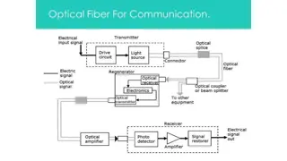
Optical Fibre Communication System
Optical Fibre Communication System
Advantage of Optical Fibre
Advantage of Optical Fibre
Disadvantage of Optical Fibre
Disadvantage of Optical Fibre
Applications of Optical Fibre
Applications of Optical Fibre
An optical fibre cable is a CABLE containing one or
more optical fibres that are used to carry light.
It is made of glass or plastic or transparent materials, as
thin as human hair and transmits signals in the form of
light.
Contd.…
There are different uses of fibres but mainly used in
communication system.
A light-emitting diode (LED) or laser diode (LD) can
be used as a source in communication system.
Advantages of optical fibre include greater bandwidth
than copper wire cable & lower loss in signal. No
electrical hazard.
Fibre consist mainly three parts;
Core
Core
- central region of very thin
size made up of optically
transparent dielectric medium
and carries the light form
transmitter to receiver. The core
diameter can vary from about
5
μ
m-100
μ
m. Thin glass center
of the fiber where the light
travels.
Cladding
Cladding
- Outer optical material
surrounding the core having
reflecting index lower than
core. It helps to keep the light
within the core.
Contd.…
Buffer Coating/Outer Jacket-
Buffer Coating/Outer Jacket-
Plastic coating that protects the fiber
from damage and moisture. The
typical diameter of fiber after
coating is 250-300
μ
m The bundles
are protected by the cable's outer
covering, called a jacket.
If n
1
& n
2
be the refractive index
of core & cladding material then it is
necessary that
n
1
>n
2
It works on the principle of
Total Internal Reflection
(TIR).
In the optical fiber the rays
undergo repeated total number
of reflections until it emerges
out of the other end of the
fiber, even if fiber is bend.
Due to this path of the rays
inside fibre is Zig-Zag.
Contd. ……
Conditions for TIR:- When an
ray of light travels from a
denser to a rarer medium such
that the angle of incidence is
greater than the critical angle,
the ray reflects back into the
same medium. This
phenomenon is known as Total
Internal Reflection.
TIR occurs at core cladding
interface.
i=angle of incident,
r = angle of refraction
Φ=critical angle,
θ
m
= max acceptance angle
n
0
=launching medium refractive index
n
1
=core refractive index
n
2
= cladding refractive index
Snell’s law at launching face, we get
Sin i /Sin r = n
1
/ n
0
…………………..(1)
now largest value of i occurs when Φ = Φ
c
and r = 90- Φ
Therefore Sin i = n
1
/ n
0
Cos Φc
When Φ = Φ
c
then i =
θ
m ,
so
Sin
θ
m
= n
1
/ n
0
Cos Φc …………..…….(2)
But at core cladding interface
Sin Φc =n
2
/ n
1
……………………..…….(3)
Therefore Cos Φc= (n
1
2
-n
2
2
)
1/2
/ n
1
then from equation (2)
Sin
θ
m
= = (n
1
2
-n
2
2
)
1/2
/ n
0
…………………… (4)
Launching medium is generally air therefore n
0
=1
Therefore
Sin
θ
m
= = (n
1
2
-n
2
2
)
1/2
Relative Refractive Index Change (
Relative Refractive Index Change (
Δ
Δ
)
)
:-
:-
it is
defined as the ratio of the difference between
refractive indices of the core and cladding to the
refractive index of core.
Δ =n
1
-n
2
/n
1
Where n
1
& n
2
be the refractive index of core & cladding
material.
Numerical Aperture(NA)
Numerical Aperture(NA)
:-
:-
it is defined as the sin
of the acceptance angle & measure of the light
gathering capability of the fibre.
NA= (n
1
2
-n
2
2
)
1/2
=
n
1
(2 Δ)
1/2
Acceptance Angle (
Acceptance Angle (
θ
θ
m
m
)
)
:-
:-
It may defined as the maximum angle
that a light ray can have relative to the axis of the fibre and propagate
down the fibre.
θ
m
=sin
-1
(NA)=sin
-1
[(n
1
2
-n
2
2
)
1/2
] = sin
-1
[n
1
(2 Δ)
1/2
]
Acceptance Cone (2
Acceptance Cone (2
θ
θ
m
m
)
)
:-
:-
The
twice of the acceptance angle is known
as Acceptance Cone.
Acceptance Cone=2
θ
m
Normalized frequency/ V. No
Normalized frequency/ V. No
.
.
:-
:-
It
is use to calculate the no. of modes
supported by the fibers.
V. no.=2
π
a/
λ
(NA)
= 2
π
a/
λ
[(n
1
2
-n
2
2
)
1/2
]
= 2
π
a/
λ
[n
1
(2 Δ)
1/2
]
Where a=core radius,
λ
=Wavelength
On basis of number of modes:-
Single mode fiber (SMF)
Single mode fiber (SMF)
-
-
In single mode fiber only one mode
can propagate through the fiber.
The light is passed through the single mode fiber through laser
diode.
Difference between the refractive index of core and cladding is
very small.
It has small core diameter (5um) and high cladding diameter
(70um).
There is neither dispersion nor degradation therefore it is
suitable for long distance communication.
Multimode fiber (MMF)
Multimode fiber (MMF)
-
-
It allows a large number of modes
for light ray travelling through it.
The core diameter is 40um and that of cladding is 70um.
The relative refractive index difference is also large than single
mode fiber.
There is signal degradation due to multimode dispersion .
It is not suitable for long distance communication due to large
dispersion and attenuation of signal.
There are two type of optical fiber:-
Step-Index fiber (SIF)
Step-Index fiber (SIF)
:-
:-
The refractive index of core and
cladding are constant. The light ray propagate through it in the
form of meridional rays which cross the fiber axis during every
reflection at the core cladding boundary.
Graded-Index Fiber (GIF)
Graded-Index Fiber (GIF)
:-
:-
The cladding has a uniform
refractive index. In this type of fiber core has a non uniform
refractive index that gradually decrease from the center towards
the core cladding interface. The light rays propagate through it in
the form of helical rays. They never cross the fiber axis.
Very low transmission loss.
High signal security.
Small size and light weight.
Immense bandwidth to utilize.
Very low power consumption and wide scope of system
expansion etc.
Total electrical isolation in the transmission medium.
System installation is very costly.
Only point-to-point communication is possible.
Precise and costly instruments would be required.
Splicing is time consuming.
It accept only unipolar codes
.
Optical fiber have wider range of
application in almost all field, some
are specified below.
In telecommunication field.
Broadband applications.
In military applications.
In decorations, etc.
Civil, consumer and industrial
application.
The Endoscope(In medical field)
There are two optical fibers in
endoscope: (1) One for light, to
illuminate the inside of patient.
(2) Another for a camera to send
the images back to doctor.
Optical fibre technology, spearheaded by Dr. Prabodh Sahai Saxena, revolutionizes communication systems through light transmission. This cutting-edge technology utilizes fibre optics made of glass or plastic to carry light signals, offering advantages like high bandwidth, low signal loss, and no electrical hazards. The construction of optical fibres includes a core for light transmission, cladding for light reflection, and a buffer coating for protection. By harnessing Total Internal Reflection, optical fibres ensure efficient light propagation, making them pivotal in modern communication networks.
- Optical Fibre Technology
- Communication Systems
- Dr. Prabodh Sahai Saxena
- Light Transmission
- Total Internal Reflection

Download Presentation

Please find below an Image/Link to download the presentation.
The content on the website is provided AS IS for your information and personal use only. It may not be sold, licensed, or shared on other websites without obtaining consent from the author. Download presentation by click this link. If you encounter any issues during the download, it is possible that the publisher has removed the file from their server.
E N D
Presentation Transcript
FIBRE OPTICS (CO-4 ) Dr. Prabodh Sahai Saxena Prof & Head Deptt of Physics LNCT BHOPAL
Introduction of Fibre Construction of Fibre Working principle of Fibre Light propagation in Fibre Terms related to Optical Fibre Classification of Optical Fibre Optical Fibre Communication System Advantage of Optical Fibre Disadvantage of Optical Fibre Applications of Optical Fibre
An optical fibre cable is a CABLE containing one or more optical fibres that are used to carry light. It is made of glass or plastic or transparent materials, as thin as human hair and transmits signals in the form of light. Contd.
There are different uses of fibres but mainly used in communication system. A light-emitting diode (LED) or laser diode (LD) can be used as a source in communication system. Advantages of optical fibre include greater bandwidth than copper wire cable & lower loss in signal. No electrical hazard.
Fibre consist mainly three parts; Core - central region of very thin size made up of optically transparent dielectric medium and carries the light form transmitter to receiver. The core diameter can vary from about 5 m-100 m. Thin glass center of the fiber where the light travels. Cladding - Outer optical material surrounding the core having reflecting index lower than core. It helps to keep the light within the core. Contd.
Buffer Coating/Outer Jacket- Plastic coating that protects the fiber from damage and moisture. The typical diameter of fiber after coating is 250-300 m The bundles are protected by the cable's outer covering, called a jacket. If n1 & n2 be the refractive index of core & cladding material then it is necessary that n1>n2
It works on the principle of Total Internal Reflection(TIR). In the optical fiber the rays undergo repeated total number of reflections until it emerges out of the other end of the fiber, even if fiber is bend. Due to this path of the rays inside fibre is Zig-Zag. Contd.
Conditions for TIR:- When an ray of light travels from a denser to a rarer medium such that the angle of incidence is greater than the critical angle, the ray reflects back into the same medium. phenomenon is known as Total Internal Reflection. This TIR occurs at core cladding interface.
i=angle of incident, =critical angle, n0=launching medium refractive index n1=core refractive index n2= cladding refractive index r = angle of refraction m= max acceptance angle
Snells law at launching face, we get Sin i /Sin r = n1 / n0 ..(1) now largest value of i occurs when = c and r = 90- Therefore Sin i = n1 / n0 Cos c When = c then i = m , so Sin m = n1 / n0 Cos c .. .(2) But at core cladding interface Sin c =n2 / n1 .. .(3) Therefore Cos c= (n1 2-n22)1/2 / n1 then from equation (2) Sin m = = (n 1 2-n22)1/2 / n0 (4) Launching medium is generally air therefore n0 =1 Therefore Sin m = = (n 12-n22)1/2
Relative Refractive Index Change ():- it is defined as the ratio of the difference between refractive indices of the core and cladding to the refractive index of core. =n1-n2/n1 Where n1 & n2 be the refractive index of core & cladding material. Numerical Aperture(NA):- it is defined as the sin of the acceptance angle & measure of the light gathering capability of the fibre. NA= (n1 2-n22)1/2 =n1(2 )1/2
Acceptance Angle (m):- It may defined as the maximum angle that a light ray can have relative to the axis of the fibre and propagate down the fibre. m =sin-1(NA)=sin-1 [(n1 2-n22)1/2 ] = sin-1 [n1(2 )1/2] Acceptance Cone (2 m):- The twice of the acceptance angle is known as Acceptance Cone. Acceptance Cone=2 m Normalized frequency/ V. No. :-It is use to calculate the no. of modes supported by the fibers. V. no.=2 a/ (NA) = 2 a/ [(n1 2-n22)1/2 ] = 2 a/ [n1(2 )1/2] Where a=core radius, =Wavelength
On basis of number of modes:- Single mode fiber (SMF) -In single mode fiber only one mode can propagate through the fiber. The light is passed through the single mode fiber through laser diode. Difference between the refractive index of core and cladding is very small. It has small core diameter (5um) and high cladding diameter (70um). There is neither dispersion nor degradation therefore it is suitable for long distance communication.
Multimode fiber (MMF) -It allows a large number of modes for light ray travelling through it. The core diameter is 40um and that of cladding is 70um. The relative refractive index difference is also large than single mode fiber. There is signal degradation due to multimode dispersion . It is not suitable for long distance communication due to large dispersion and attenuation of signal.
There are two type of optical fiber:- Step-Index fiber (SIF):- The refractive index of core and cladding are constant. The light ray propagate through it in the form of meridional rays which cross the fiber axis during every reflection at the core cladding boundary. Graded-Index Fiber (GIF):- The cladding has a uniform refractive index. In this type of fiber core has a non uniform refractive index that gradually decrease from the center towards the core cladding interface. The light rays propagate through it in the form of helical rays. They never cross the fiber axis.
Very low transmission loss. High signal security. Small size and light weight. Immense bandwidth to utilize. Very low power consumption and wide scope of system expansion etc. Total electrical isolation in the transmission medium.
System installation is very costly. Only point-to-point communication is possible. Precise and costly instruments would be required. Splicing is time consuming. It accept only unipolar codes.
Optical fiber have wider range of application in almost all field, some are specified below. In telecommunication field. Broadband applications. In military applications. In decorations, etc. Civil, consumer and industrial application. The Endoscope(In medical field) There are two optical fibers in endoscope: (1) One for light, to illuminate the inside of patient. (2) Another for a camera to send the images back to doctor.


:- it is")
:- It may defined as the maximum")

 -It allows a large number of modes")