Understanding Fiber Characteristics in Fiber Optics and Laser Instrumentation

This module explores the mechanical characteristics such as strength, static fatigue, and dynamic fatigue of glass fibers in fiber optics. It discusses the cohesive bond strength of glass fibers, static fatigue under humid conditions, and dynamic fatigue during installation and operation. The transmission characteristics like attenuation, defining signal loss in optical power, are also highlighted. Detailed insights into fiber behavior under different stress conditions provide valuable understanding for professionals in the field.

Download Presentation

Please find below an Image/Link to download the presentation.
The content on the website is provided AS IS for your information and personal use only. It may not be sold, licensed, or shared on other websites without obtaining consent from the author. Download presentation by click this link. If you encounter any issues during the download, it is possible that the publisher has removed the file from their server.
E N D
Presentation Transcript
FIBER CHARACTERISTICS EIBX02 FIBRE OPTICS AND LASER INSTRUMENTATION Module 2
Mechanical characteristics 1. Strength 2. Static fatigue 3. Dynamic fatigue 26.7.18 -P.R.Hemavathy, AP(SG), EIE 2
Strength The cohesive bond strength of the constituent atoms of a glass fiber governs its theoretical intrinsic strength. Maximum tensile strength of 14 GPa is observed in short length glass fibers. This is closed to the 20 GPa tensile strength of steel wire. The difference between glass and metal is that, under an applied stess, glass will extend elastically up to its breaking strength whereas metal can be stretched plastically well beyond their elastic range Eg: Copper wires can be elongated plastically 18.9.18 -P.R.Hemavathy, AP(SG), EIE 3
Static fatigue It refers to the slow growth of the existing flaws in the glass fiber under humid conditions and tensile stress. This gradual flaw growth causes the fiber to fail at a lower stress level than that which could be reached under a strength test. The flaw shown propagates through the fiber because of chemical erosion of the fiber material at the flaw tip. The primary cause of this erosion is the presence of water in the environment which reduces the strength of SiO2 in glass. The speed of the growth reaction is increased when the fiber is put under test. Fused silica offers the most resistance of glasses in water. In general, coating are applied to the fiber immediately during the manufacturing process which affords a good degree of protection against environmental corrosion. 18.9.18 -P.R.Hemavathy, AP(SG), EIE 4
Dynamic fatigue When an optical cable is being installed on a duct, it experiences repeated stress owing to surging effects. The surging is caused by varying degrees of friction between the optical cable and the duct or guiding tool on a curved route. Varying stress also arises in aerial cables that are set into transverse vibration by the wind. Theoritical and experimental investigation have shown that the time to fail under these conditions is related to the maximum allowable stress by the same life time parameter that are in the cases of statics stress that increases at a constant rate. 18.9.18 -P.R.Hemavathy, AP(SG), EIE 5
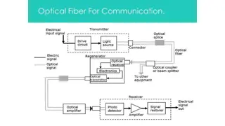
Transmission Characteristics Attenuation Attenuation is the loss of optical power as light travels along the fiber. Signal attenuation is defined as the ratio of optical input power (Pi) to the optical output power (Po). Optical input power is the power injected into the fiber from an optical source. Optical output power is the power received at the fiber end or optical detector. 18.9.18 -P.R.Hemavathy, AP(SG), EIE 6
Each mechanism of loss is influenced by fiber- material properties and fiber structure. However, loss is also present at fiber connections i.e. connector, splice, and coupler losses. 18.9.18 -P.R.Hemavathy, AP(SG), EIE 7
Absorption losses Absorption in optical fibers is explained by three factors: Imperfections in the atomic structure of the fiber material The intrinsic or basic fiber-material properties The extrinsic (presence of impurities) fiber-material properties Imperfections in the atomic structure induce absorption by the presence of missing moleculesor oxygen defects. Absorption is also induced by the diffusion of hydrogen molecules into the glass fiber. 18.9.18 -P.R.Hemavathy, AP(SG), EIE 8
Intrinsic Absorption.- Intrinsic absorption is caused by basic fiber material properties. If an optical fiber were absolutely pure, with no imperfections or impurities, then all absorption would be intrinsic. Intrinsic absorption sets the minimal level of absorption Extrinsic Absorption.- Extrinsic absorption is caused by impurities introduced into the fiber material. Trace metal impurities, such as iron, nickel, and chromium, OH ions are introduced into the fiber during fabrication. Extrinsic absorption is caused by the electronic transition of these metal ions from one energy level to another 18.9.18 -P.R.Hemavathy, AP(SG), EIE 9
Scattering losses Basically, scattering losses are caused by the interaction of light with density fluctuations within a fiber. Density changes are produced when optical fibers are manufactured. During manufacturing, regions of higher and lower molecular density areas, relative to the average density of the fiber, are created. Light traveling through the fiber interacts with the density areas as shown in Light is then partially scattered in all direction. 18.9.18 -P.R.Hemavathy, AP(SG), EIE 10
In commercial fibers operating between 700- nm and 1600-nm wavelength, the main source of loss is called Rayleigh scattering. As the wavelength increases, the loss caused by Rayleigh scattering decreases. If the size of the defect is greater than onetenth of the wavelength of light, the scattering mechanism is called Mie scattering. 18.9.18 -P.R.Hemavathy, AP(SG), EIE 11
Rayleigh scattering It occurs because the molecules of silicon dioxide have some freedom when adjacent to one another. Thus, setup at irregular positions and distances with respect to one another when the glass is rapidly cooled during the final stage of the fabrication process. Those structural variations are seen by light as variations in the refractive index, thus causing the light to reflect that is, to scatter in different directions 18.9.18 -P.R.Hemavathy, AP(SG), EIE 12
Rayleigh scattering is a scattering of light by particles much smaller than the wavelength of the light, which may be individual atoms or molecules. Rayleigh scattering is a process in which light is scattered by a small spherical volume of variant refractive index, such as a particle, bubble, droplet, or even a density fluctuation. As light travels in the core, it interacts with the silica molecules in the core. Rayleigh scattering is the result of these elastic collisions between the light wave and the silica molecules in the fiber. Rayleigh scattering accounts for about 96 percent of attenuation in optical fiber 18.9.18 -P.R.Hemavathy, AP(SG), EIE 13
Causes of Rayleigh Scattering: It results from non-ideal physical properties of the manufactured fiber. It results from inhomogeneities in the core and cladding. Because of these inhomogeneities problems occur like a) Fluctuation in refractive index b) density and compositional variations. 18.9.18 -P.R.Hemavathy, AP(SG), EIE 14
Minimizing of Rayleigh Scattering: Rayleigh scattering is caused due to compositional variations which can be reduced by improved fabrication. Equation of Rayleigh Scattering: Light scattering can be divided into domains based on a dimensionless size parameter, which is defined as = Dp/ where Dp is the circumference(The boundary line of a circle) of a particle and is the wavelength of incident radiation. Based on the value of , these domains are: <<1: Rayleigh scattering (small particle compared to wavelength of light) 1: Mie scattering (particle about the same size as wavelength of light) 18.9.18 -P.R.Hemavathy, AP(SG), EIE 15
Mie scattering Non perfect cylindrical structure of the fiber and imperfections like irregularities in the core-cladding interface, diameter fluctuations, strains and bubbles may create linear scattering which is termed as Mie scattering Mie scattering is a scattering of light by particles approximately equal to the wavelength of the light, which may be individual atoms or molecules. 18.9.18 -P.R.Hemavathy, AP(SG), EIE 16
Causes of Mie Scattering Occurred due to inhomogeneities in the composition of silica. (i.e. inhomogeneities in the density of SiO2 ) Irregularities in the core-cladding interface, difference in core cladding refractive index, diameter fluctuations, due to presence of strains and bubbles. The scattering caused by such inhomogeneities is mainly in the forward direction depending upon the fiber material, design and manufacture. 18.9.18 -P.R.Hemavathy, AP(SG), EIE 17
Minimizing of Mie scattering Mie scattering is mainly caused by inhomogeneities which can be minimized by removing imperfection due to glass manufacturing process Carefully controlled extrusion(To push or thrust out) and coating of the fiber Both Mie and Rayleigh scattering are considered elastic scattering (elastic scattering is also called Linear scattering) processes, in which the energy (and thus wavelength and frequency) of the light is not substantially changed. 18.9.18 -P.R.Hemavathy, AP(SG), EIE 18
Nonlinear scattering losses Specially at high optical power levels scattering causes disproportionate attenuation, due to non linear behavior. Because of this non linear scattering the optical power from one mode is transferred in either the forward or backward direction to the same, or other modes, at different frequencies. The two dominant types of non linear scattering are : a) Stimulated Brillouin Scattering and b) Stimulated Raman Scattering. 18.9.18 -P.R.Hemavathy, AP(SG), EIE 19
Stimulated Brillouin Scattering: This is defined as the modulation of light through thermal molecular vibration within the fiber. The scattered light contains upper and lower side bands along with incident light frequency. An incident photon produces a scattered photon as well as a photon of acoustic frequency. 18.9.18 -P.R.Hemavathy, AP(SG), EIE 20
The frequency shift is maximum in the backward direction and it is reduced to zero in the forward direction. The threshold optical power for Brillion scattering is proportional to d2 2 B where, d is the fiber core diameter is the operating wavelength and B is the fiber attenuation in decibels. 18.9.18 -P.R.Hemavathy, AP(SG), EIE 21
Stimulated Raman Scattering Here, the scattered light consists of a scattered photon and a high frequency optical photon. Further, this occurs both in the forward and backward direction in the optical fiber. The threshold for Raman scattering is about three orders of magnitude higher than the Brillouin threshold for the given fiber. 18.9.18 -P.R.Hemavathy, AP(SG), EIE 22
The threshold optical power for Raman scattering is proportional to d2 R where, d is the fiber core diameter is the operating wavelength and R is the fiber attenuation in decibels. 18.9.18 -P.R.Hemavathy, AP(SG), EIE 23
Dispersion Dispersion occurs when a pulse of light is spread out during transmission on the fiber. A short pulse becomes longer and ultimately joins with the pulse behind, making recovery of a reliable bit stream impossible. (In most communications systems bits of information are sent as pulses of light. 1 = light, 0 = dark. But even in analogue transmission systems where information is sent as a continuous series of changes in the signal, dispersion causes distortion.) 18.9.18 -P.R.Hemavathy, AP(SG), EIE 24
Material dispersion (chromatic dispersion):- Both lasers and LEDs produce a range of optical wavelengths (a band Of light) rather than a single narrow wavelength. The fiber has different refractive index characteristics at different wavelengths and therefore each wavelength will travel at a different speed in the fiber. Thus, some wavelengths arrive before others and a signal pulse disperses (or smears out). 18.9.18 -P.R.Hemavathy, AP(SG), EIE 25
Intermodal Dispersion When using multimode fiber, the light is able to take many different paths or modes as it travels within the fiber. The distance traveled by light in each mode is different from the distance travelled in other modes. When a pulse is sent, parts of that pulse (rays or quanta) take many different modes (usually all vailable modes). Therefore, some components of the pulse will arrive before others. The difference between the arrival times of light taking the fastest mode versus the slowest obviously gets greater as the distance gets greater. 18.9.18 -P.R.Hemavathy, AP(SG), EIE 26
18.9.18 -P.R.Hemavathy, AP(SG), EIE 27
Waveguide dispersion Waveguide dispersion is a very complex effect and is caused by the shape and index profile of the fiber core. However, this can be controlled by careful design and, in fact; waveguide dispersion can be used to counteract material dispersion. Dispersion in different fibers: Mode dispersion > .material dispersion > waveguide dispersion 18.9.18 -P.R.Hemavathy, AP(SG), EIE 28
Splicers For longer distance communication, we have to connect one fiber with other fiber and mean while the losses must be minimized. The process of connecting the two fibers for permanent requirement is called Splicing. Depend upon requirement splicing is classified into two type. They are, 1. Splices For permanent connections. 2. Connectors For temporary connections. 18.9.18 -P.R.Hemavathy, AP(SG), EIE 29
Elastomeric splice It is made by an elastomer material. It consists of a hole, so that we have to insert the two fibers from two ends for rigid hold. The elastomer is covered by a glass sleeve with ends in such a way that it aligns the fibers into the elastomeric splice. The gel has the same refractive index is used as an adhesive. Thus the fibers are connected. 18.9.18 -P.R.Hemavathy, AP(SG), EIE 30
Elastomeric splice 18.9.18 -P.R.Hemavathy, AP(SG), EIE 31
Four Rod Splices The four glass rods are attached with one end of the fiber to hold another fiber firmly. Initially the rods curve slightly outward, so that the fiber can be easily inserted into it. By a suitable mechanical pressure the rods are made to be tightly clamping the two fibers.Here also gel is used for adhesion. 18.9.18 -P.R.Hemavathy, AP(SG), EIE 32
Fusion Splices: Here two ends of the fiber is fused together with the help of a special equipment, using a high voltage electric arc. Hence, these splices are called fusion splices. Here the losses are minimized due to self-alignment system. 18.9.18 -P.R.Hemavathy, AP(SG), EIE 33
REFERENCES Gerd Keiser, Optical Fibre Communications , McGraw-Hill, International Edition, 2010. John M senior, Optical fiber communications principles and practice , 3rd edition, Pearson Education Limited, 2009. 18.9.18 -P.R.Hemavathy, AP(SG), EIE 34